Vol. 16, No. 3, 2013, 169-176
http://dx.doi.org/10.5229/JKES.2013.16.3.169
− 169 −
제일원리계산을 이용한 리튬이차전지 양극활물질 LiNiO2의 표면 특성에 관한 연구
최희성*·이맹은 (주)삼성SDI 중앙연구소
(2013년 7월 23일 접수 : 2013년 8월 19일 채택)
First-Principles Investigation of the Surface Properties of LiNiO
2as Cathode Material for Lithium-ion Batteries
Heesung Choi* and Maeng-Eun Lee R&D Center, Samsung SDI Co., Ltd.,
(Received July 23, 2013 : Accepted August 19, 2013)
초 록
현재 이차전지에서 사용중인 양극활물질은 구조 안정성이 높은 층상구조(Layered Structure)의 리 튬 금속 산화물(Solid State Lithium Oxide Compounds)이 주로 사용된다. 최근에는 리튬이차전 지의 성능향상을 위해서 음극활물질과 전해질 사이의 계면뿐만 아니라, 양극활물질과 전해질 사이 의 계면에 관한 연구가 활발히 진행되고 있으며, 이러한 계면의 연구를 위해서는 음극활물질 뿐만 아니라, 양극활물질의 표면에 관한 연구도 선행적으로 이루어져야 하는 상황이다. 대표적인 리튬 금속 산화물질인 니켈산리튬(LiNiO2)과 코발트산리튬(LiCoO2)은 서로 매우 유사한 구조를 갖는 층상구조의 양극활물질이다. 코발트산리튬이 다양한 실험적, 이론적 연구가 진행된 반면에, 니켈산 리튬은 실험적 연구에 비해서 이론적 연구가 부족하다. 따라서, 본 연구에서는 니켈산리튬의 X-선 회절계 측정 결과(XRD data)에 나오는9개의 표면 방향을 범밀도함수이론(Density Functional Theory)을 이용하여 니켈산리튬 표면의 표면 에너지를 계산하였다. 니켈산리튬의 X-선 회절계 측 정 결과(XRD data)에서는 (003), (104), (101), (110) 결정 등등이 순차적으로 주요하게 존재하는 것으로 확인되었다. 그러나 시뮬레이션을 이용한 각각의 표면 에너지 계산 결과, X-선 회절계 측 정 결과와 다른 순서로 안정한 표면 에너지가 나타나는 결과를 얻었다. 따라서 에너지적으로 안정 한 표면이자, X-선 회절계에서 주요하게 나타나는 (104)와 (101) 방향의 니켈산리튬 표면이 많이 노출되어 Li 이온의 충방전시 리튬의 삽입·탈리에 영향을 줄 것으로 예상된다.
Abstract : Solid state lithium oxide compounds of layered structure, which has high stability of structure, are mainly used as the cathode materials in lithium-ion batteries (LIBs). Recently, the investigation of Solid Electrolyte Interphase (SEI) between active materials and electrolyte has been focusing to improve the performance of lithium-ion batteries. For the investigation of the SEI, the study of surface properties of cathode materials and anode materials is also required in advance. LiNiO2 and LiCoO2 are very similar layered structure of cathode active materials and representative solid state lithium oxide compounds in LIBs. Various experimental and the- oretical studies have been doing for LiCoO2. The theoretical investigation of LiNiO2 is not suf- ficient, however, even if experimental studies of LiNiO2 are enough. In this study, the surface energies of nine facets of LiNiO2 crystal facets were calculated by Density Functional Theory.
*E-mail: [email protected]
In XRD data of LiNiO2, (003), (104), (101), et al. facets are main surfaces in order. However, the results of calculation are different with XRD data. Thus, both (104) and (101) facets, which are energetically stable and measured in XRD, are mainly exposed in the surface of LiNiO2 and it is expected that intercalation and de-intercalation of Li-ion will be affected by them.
Keywords : LiNiO2, Cathode material, Surface properties, Lithium-ion battery, Ab-initio calculation
1. 서 론
리튬이온전지(lithium-ion battery, LIB)는 1991년 일 본의 소니(Sony)와 아사히 카세이(Asahi KASEI Co.) 가 최초로 상용화된 제품을 출시한 이후, 지금까지 휴 대용 전자기기-노트북, 휴대폰, 테블릿 등에서 가장 널 리 쓰이고 있는 배터리이며, 현재는 그 범위를 확장시 켜 전동공구, 전기자전거, 자동차 및 에너지 저장 장 치 (Energy Storage System, ESS)에도 적용되고 있 다.1-3)
리튬이온전지의 용량은 양극 활물질에 따라 결정된 다. 현재 사용중인 양극활물질의 종류는 스피넬 구조 (Spinel Structure)의 망간계리튬(Manganese Spinel), 인산철리튬(Lithium Iron Phosphate), 층상구조의 망간 계리튬(Lithium Manganese Oxide) 그리고 스피넬 구 조와 층상구조를 갖는 니켈/망간/코발트리튬(Lithium Nickel Manganese Cobalt) 등이 있으나, 그 중에서 구조 안정성이 높은 층상구조(Layered Structure)의 리 튬 금속 산화물(Solid State Lithium Oxide Compounds)이 주로 사용된다.3,4) 층상구조의 LiMO2
(M=Co,Ni,Mn)는 전이금속과 산소로 구성된 금속 산 화물층(Transition metal layer)과 리튬을 둘러싸고 있 는 산소층(Oxygen layer)이 서로 교대로 배열하고 있 다.3) MO2 층 내부는 강한 이온결합(ionic bonding)을 형성하며, MO2와 MO2 층 사이에 쿨롱 반발력 (coulomb interaction)이 작용하여 리튬이온의 삽입 (intercalation)과 탈리(de-intercalation)가 가능하다.3) 이 러한 층상구조의 양극활물질 중에서 가장 많이 쓰이 는 물질들로는 코발트산리튬 (LiCoO2)와 니켈산리튬 (LiNiO2)이 있으며, 서로 유사한 구조를 갖고 있다. 코 발트산리튬과 니켈산리튬에서 리튬 이온이 2차원 평 면을 따라서 확산할 수 있으므로 이온전도도(ionic conductivity)가 높으므로, 4 V 이상의 고용량 리튬이 차전지의 양극활물질로 사용될 수 있다.3) 지금까지 코 발트산리튬과 니켈산리튬에 관한 다양한 연구들이 수 행되어 왔는데, 대부분은 양극활물질의 거시적 물성에 의한 결정상과 결정 격자내 리튬이온의 이동을 보기 위 한 연구들이었다.1-11)리튬이차전지의 성능 향상을 위한 최근 연구 동향은 격자내 리튬이온의 이동뿐 아니라, 활물질과 전해질의 계면층(Solid Electrolyte Interface,
SEI)에 관한 연구가 활발히 진행되고 있다.15-20) 특히, 리튬이차전지의 성능을 제어하고 안정성과 수명을 향 상시키기 위해서는 계면층에 대한 이해 및 계면층 형 성 메커니즘에 대한 이해가 매우 중요하다.15) 리튬이차 전지에서 전해질과 활물질 사이에서 생기는 계면을 살 펴보면, 음극활물질 표면에서는 계면층이 잘 형성되지 만, 양극활물질 표면에서는 계면층이 얇게 형성되거나 간혹 발견된다고 알려져 있다.15,16) 양극 소재로 사용 되는 니켈산리튬, 코발트산리튬, 망간산리튬의 표면에 는 일반적인 경우 자연적으로 탄산리튬(Li2CO3)층이 생성되어 표면보호층(native layer)이 존재한다.15) 탄산 리튬층은 전극소재를 합성하는 과정 중에 공기에서 흡 수된 이산화탄소(CO2)와의 반응에 의하여 형성된다.15) 표면층의 탄산리튬은 전해질로 용출된 후, 음극쪽으로 이동하여 표면층을 형성할 수도 있다고 알려져 있다.15) 이렇게 자연적으로 형성되는 표면 보호층은 전기화학 적 임피던스 분광(EIS) 분석법에 의해서도 확인되어, 양극에도 계면층이 존재한다는 사실이 알려졌다.17)양 극표면에 처음으로 계면층이 형성되면, 전해질의 리튬 이온이 계면층을 통과해 양극표면에 접촉하게 되어 전 자전달이 일어나고, 그 결과 산화-분해 반응이 발생하 면서 추가적인 계면층을 형성하게 된다.15)초기 싸이 클 과정에서 형성된 양극 표면의 계면층은 싸이클 횟 수의 증가와 함께 셀 내부의 저항을 증가시켜서 셀의 전기화학적 성능, 수명 및 열적 안정성을 저하시키는 요인이 될 수도 있다.15) 따라서 앞에서 언급한 바와 같이 양극활물질의 계면층에 대한 심도깊은 연구가 더 필요하며, 이러한 계면층을 연구하기 위해서는 활물질 의 표면에 대한 연구가 선행되어야 한다. 1954년에 니 켈산리튬의 합성이 최초로 보고된 이후, 니켈산리튬은 리튬이차전지의 양극활물질로써 사용되었으며, 활물질 결정의 거시적 물성에 대한 연구는 실험적인 접근방 식과 이론적인 접근방식으로 많이 진행되었다.1-11)그 러나 계면을 연구하기 위해 선행되어야 하는 표면에 관한 이론적인 연구는 아직 미흡한 편이었다. 그런데 최근에 니켈산리튬과 코발트산리튬의 표면 구조에 관 한 연구가 진행이 되고 있다.12,13) X-선 회절계 측정 결과를 토대로 양극 표면에 관한 이론적인 연구가 진 행되는 것은 바람직하지만, 표면 구조의 일부분의 특 성만을 연구하는 점은 아쉽다.
따라서 본 연구는 니켈산리튬의 표면 특성에 관한 기 존의 연구 범위13)를 확장하여 X-선 회절계(XRD)에서 주요하게 나타나는 9개의 니켈산리튬의 표면을 살펴보 기로 한다. 니켈산리튬의 표면 특성의 이론적인 연구를 위하여 제일원리계산(First-principle calculat-ion)을 이용 하였으며, 이를 통해서 표면 에너지를 계산하였다.
2. 전산해석 모델 2.1. 전산모사방법
본 연구에서는 니켈산리튬의 다양한 표면 에너지 및 전자구조를 계산하기 위하여 범밀도함수이론(Density Functional Theory)을 이용한 제일원리계산방법(first- principle calculation)21-23)을 도입하였으며, 범밀도함수를 풀기 위하여 Blchl에 의해 제안된 Projector Augmented Wave (PAW) Method24)를 사용하였다. 또한, 이러한 계산 을 수행하기 위해서는 적절한 교환-상관 범함수 (Exchange-correlation functional, XC-functional)를 선택해 야 하는데, 전이금속의 연구에 가장 적합하다고 알려진 일반화 물매 근사(General Gradient Approxim- ation(GGA))25)을 적용하고 Perdew-Burke-Ernzerhof (PBE) 파라미터를 사용하였다.26) 니켈산리튬을 구성하는 산소의 2s, 2p 전자, 리튬의 2s 전자, 그리고 니켈의 3d, 4s 전자들은 원자가 전자(valence electron)로, 그 외 모든 전자들은 핵심부 전자(core electron)로 간주하였다. 이러 한 계산을 수행하기 위하여 ‘VIENNA ab-initio simulation package (VASP)’27,28)을 사용하였으며, ultrasoft pseudopotential29,30)과 plane-wave basis set을 이용하였다.
니켈산리튬의 체적(bulk) 및 표면 구조 제작에는 Material Studio (Accelrys Software Inc.)가 사용되었다.
X-선 회절계 측정 결과를 보면, 니켈산리튬의 결정 구조는 주로 (003), (104), (101)방향의 결정들이 많이 나타나는 것으로 알려져 있으며, X-선 회절계 그래프 는 다음과 같다.7) 그러므로 니켈산리튬 8개의 방향-
(003), (104), (101), (102), (110), (105), (107), (113)방향-결정을 갖는 표면 계산이 이번 연구의 주요 내용이 되겠다.
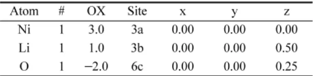
니켈산리튬의 표면을 제작하기 위하여, 우선 주기적 경계 조건(periodic boundary condition)하에서 니켈산 리튬의 체적(bulk)31)의 전산모사를 수행하였다. 니켈산 리튬은 R-3m HR의 space Group에 속해 있으며, 니켈 산리튬 체적의 구조 정보는 Table 1과 같다.
전산모사를 통해 얻은 체적 구조 결과의 신뢰성을 보기 위해서, 계산 결과와 참조문헌간의 값을 비교한 표는 Table 2와 같다.
이와 같이 전산모사를 통해 얻은 체적 구조를 이용 하여 주기적 경계 조건하에서 x 와 y 방향으로 표면을 제작하고, z 방향으로는 진공 영역을 설정하였다. 모든 표면 구조는 x와 y 방향으로 반복되며, z 방향으로는 표면간의 상호작용을 고려하여 15Å 두께의 진공영역 으로 구분하였다. 모든 표면 구조의 초격자(supercell) 에 적용된 브릴루리앙 존(brillouin zone)에 사용된 k- point grid는 8개의 표면방향에 따라 다음과 같이 다른 값들로 적용되었다. 예를 들어, (003) 표면에는 (10X10X1) Monkhorst-Pack[32] k-point grid, (104) 표면에는 (4X9X1) Monkhorst-Pack k-point grid, (101) 표면에는 (5X9X1) Monkhorst-Pack k-point grid가 적용되었다. 또한, 표면 구조 계산을 위한 컷-오 프 에너지(cutoff energy)는 500 eV로 설정하였다.
2.2. 니켈산리튬의 표면 구조
본 연구에서 다루는 니켈산리튬의 9개의 표면 중에 서 X-선 회절계에서 주요하게 나타나는 세 가지의 니 켈산리튬의 (003), (104), (101) 표면 구조를 예로 들 Fig. 1. Typical XRD pattern of LiNiO2 powders calcined
at 750oC.7)
Table 1. The Atomic structure of LiNiO2 bulk
Atom # OX Site x y z
Ni 1 3.0 3a 0.00 0.00 0.00
Li 1 1.0 3b 0.00 0.00 0.50
O 1 −2.0 6c 0.00 0.00 0.25
Table 2. Calculated and experimental values of the structural parameters of bulk LiNiO2. a and c are the lattice constant, V is the volume of unit cell of LiNiO2. Experimental values are from Ref. 16
GGA(this study) Ref. 8 Ref. 14 Expt.
a(Å) 2.90 2.90 2.89 2.88
c(Å) 14.21 14.20 14.33 14.19
c/a 4.90 4.9 - 4.93
V(Å3) 103.55 - - 101.79
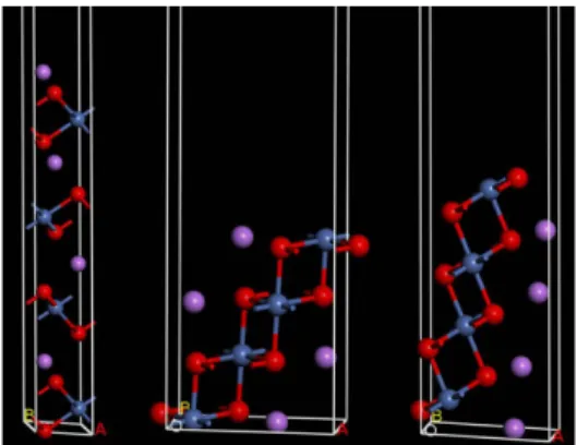
어 보자. 우선 원자구조는 Fig. 2에서 보는 것과 같으 며, c축에 수직한 구조이다.
니켈산리튬의 표면 구조를 계산할 때, 체적과 표면 층으로 구별하여 전산모사를 한다. 본 연구에서는 표면 구조 상부의 Li층, Ni층, O층을 표면층(surface layer) 으로 정의하여 원자들을 움직이고 이완(relax)시킨다.
그리고 나머지 부분을 체적으로 정의하여 모든 원자들 을 고정시킨다.
일반적으로 표면 에너지는 무한한 결정구조를 두 개 의 유한한 결정구조로 나누는데 필요한 에너지라고 정 의한다. 따라서 본 연구에서는 표면 에너지(surface energy)를 구하는 공식은 다음과 같이 주어진다.14)
(1)
여기에서 Eslab는 구조안정화(Geometry Optimization) 된 표면 구조의 전체 에너지이며, Ebulk는 체적의 전체 에너지를 원자의 개수로 나눈 값이며, N은 표면 구조를 이루고 있는 원자의 개수이다.14) 마지막으로 숫자 2가 의미하는 것은 표면이 양쪽에 존재하기 때문이며, S는 각각의 표면의 넓이이다.14)
3. 전산계산 및 해석 3.1. 표면 구조의 전산 계산
가장 안정된 표면을 찾기 위해서, 니켈산리튬의 (003), (104), (101), (102), (110), (105), (107), (113), (012) 방향 표면에 대하여 표면층의 종류와 두께에 따 라서 표면 에너지가 어떻게 변화하는지를 알아보았다.
그 중에서 X-선 회절계에서 주요하게 나타나는 세가지 Esurf 1
2S---(Eslab–N E⋅ bulk)
=
Fig. 2. Various atomic structures of layered LiNiO2 with R3m symmetry. (a) is active view, (b) is view from the side and (c) is view from the top of atomic structures of layered LiNiO2 From left, (003), (104) and (101) surfaces.
Red is Oxygen atom, Purple is Lithium atom and metallic blue is Nickel atoms.
Fig. 3. Definition of a single layer of (003) surface. A single layer of (003) surface consists of one Li layer, one Nickel layer and two Oxygen layers.
의 니켈산리튬의 (003), (104), (101) 표면 구조의 전산 계산을 예로 보겠다.
3.1.1 (003) 표면
(003) 표면층은 Fig. 3에서 보듯이, Li-O-Ni-O가 반복 되는 층상구조이다. 따라서 1개의 리튬원자층, 1개의 니 켈원자층 그리고 2개의 산소원자층을 하나의 단일층으 로 정의하였다. 또한, 최표면층(top layer)이 어떤 원자 로 되어 있을 때 가장 안정한가를 보기 위하여, 리튬이 가장 위에 있는 경우(Li-terminated)와 산소가 가장 위 에 있는 경우(O-terminated)의 표면 에너지를 비교해보 았다(Fig. 4). Table 3에서 보듯이, 리튬 원자가 최표면 에 드러나 있는 경우가 가장 안정된 구조인 것으로 나 타났다. 그리하여 리튬 원자가 최표면에 드러나 있는 표면구조에서 표면구조의 두께를 3층(3 layer)에서 6층 (6 layer)까지 늘려가면서 계산을 수행하였다.
3.1.2 (104) 표면
(104) 표면층은 Fig. 5에서 보듯이, 리튬과 산소와 니켈 이 모두 같은 층에 존재하는 층상구조이다. 따라서 1개의 리튬원자, 1개의 니켈원자 그리고 2개의 산소원자를 갖는 최표면층을 표면층으로 정의하고, 나머지는 체적으로 정 의하였다. 그리고 표면구조의 두께를 3층 (3 layer)에서 6 층 (6 layer)까지 늘려가면서 계산을 수행하였다.
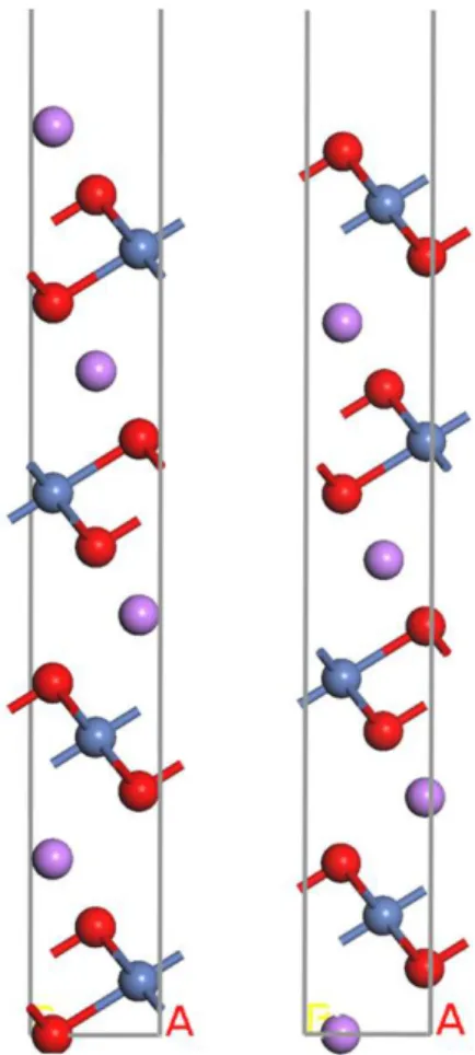
3.1.3 (101) 표면
(101) 표면층은 Fig. 6에서 보듯이, z축 방향으로 Li-O- Ni-O가 반복되는 층상구조이다. 그러나 리튬층이 표면에 서 수직방향 (z축 방향)으로 존재한다. 따라서 여기서도 1개의 리튬원자층, 1개의 니켈원자층 그리고 2개의 산소 원자층을 하나의 단일층으로 정의하였다. 또한, 최표면층 이 어떤 원자로 되어 있을 때 가장 안정한가를 보기 위 하여, 니켈이 가장 위에 있는 경우(Ni-terminated)와 산소 가 가장 위에 있는 경우(O-terminated)의 표면 에너지를 비교해보았다 (Fig. 7). (104) 표면의 경우, Fig. 7에서 보듯이 산소가 가장 위에 있는 경우가 두 가지로 나뉜 다. Table 4에서 보듯이, 산소층이 최표면에 드러나 있는 경우가 가장 안정된 구조인 것으로 나타났다. 그리하여 산소층이 최표면에 드러나 있는 안정된 구조를 이용하여 Fig. 4. Li-terminated LiNiO2 (003) surface (Left) and O-
terminated LiNiO2 (003) surface (Right). Li-terminated surface is more stable than O-terminated surface.
Table 3. Surface Energies with different atom-terminated top layer of LiNiO2 (003) surfaces. Li-terminated surface has lower surface energy than Oxygen-terminated surface. This means that Li-terminated surface is the most stable surface in LiNiO2 (003) surface.
Atom type of top layer Esurf (eV/Å2)
Li-terminated 0.146
Oxygen-terminated 0.202
Fig. 5. Definition of a single layer of (104) surface. A single layer of (104) surface consists of one Li atom, one Nickel atom and two Oxygen atoms.
3층(3 layer)부터 6층(6 layer)까지 표면 구조의 두께를 늘 려가면서 계산을 수행하였다.
3.1.4. (102), (110), (105), (107), (113), (012) 표면 나머지 표면들도 위의 세 가지 방향의 표면과 같은 방식으로 계산이 수행되었다. (102), (110), (105), (107), (113), (012) 표면에서 (110) 표면을 제외한 모든 구조가 산소가 가장 위에 있는 경우의 표면 에 너지가 가장 안정되는 것으로 나타났다. (110) 표면은 (104) 표면처럼 최표면에 리튬과 산소와 니켈이 모두 한층에 존재하는 층상구조이다. 따라서 (110) 표면구 조는 (104) 표면구조와 같은 방식으로 정의하였다. 이 렇게 6개의 표면구조들도 각 표면방향에 따라서 정의 를 하고, 3개의 층(3 layer)부터 6개의 층(6 layer)까지 표면구조의 두께를 늘려가면서 계산을 수행하였다.
Fig. 7. Ni-terminated LiNiO2 (101) surface (Left), O1- terminated (101) surface (middle) and O2-terminated (101) surface (Right). The O1-terminated surface (middle) has the lowest surface which, means it is the most stable (101) surface.
Table 4. Surface Energies with different atom-terminated top layer of LiNiO2 (104) surfaces. Oxygen1-terminated surface has the lowest surface energy than Oxygen2- terminated surface and Nickel-terminated surface. This means that Oxygen1-terminated surface is the most stable surface in LiNiO2 (104) surface
Atom type of top layer Esurf (eV/Å2)
Oxygen1-terminated 0.077
Oxygen2-terminated 0.128
Nickel-terminated 0.130
Table 5. Surface Energies vs. the number of layers. (Unit of surface energy is eV/Å2)
LNO(003)LNO(104)LNO(101)LNO(110)LNO(012) 3layer 0.147 0.034 0.077 0.09 0.082 4layer 0.146 0.036 0.077 0.086 0.084 5layer 0.146 0.036 0.077 0.087 0.083 6layer 0.15 0.036 0.077 0.088 0.083
LNO(102)LNO(107)LNO(105)LNO(113) 3layer 0.091 0.063 0.117 0.089 4layer 0.092 0.063 0.103 0.065 5layer 0.092 0.063 0.103 0.065 6layer 0.091 0.062 0.104 0.067 Fig. 6. Definition of a single layer of (104) surface. A
single layer of (104) surface consists of one Li layer, one Nickel layer and two Oxygen layers.
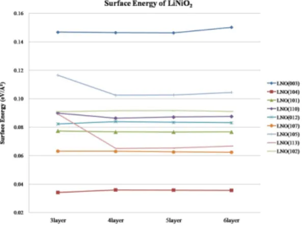
Fig. 8. Graph of Surface Energies vs. the number of layers. It is shown that the (004) LiNiO2 surface has the lowest surface energies in all layers. Thus, (004) surface is the most stable surface while (003) surface is the most unstable surface among all eight surfaces, even if the (003) surface has the dominant surface facets in LiNiO2 structure.
3.2. 표면구조의 두께 증가에 따른 9개의 표면구조의 표면 에너지의 변화
앞에서 언급한 니켈산리튬의 (003), (104), (101), (102), (110), (105), (107), (113), (012) 방향 표면 구조의 두께 증가에 따른 각각의 표면 에너지에 관한 결과는 아래의 Table 5와 Fig. 8과 같다.
표면 에너지 및 표면 안정성이 X-선 회절계에 의해 측정된 결정구조와 일치할 것이라는 예상과 다르게, X-선 회절계 그래프에서 가장 큰 피크를 보여준 (003) 표면이 가장 불안정한 구조이며, 오히려 (104) 표면이 가장 안정된 구조라는 결과가 나왔다. 이러한 결과는 실제 니켈산리튬의 결정구조는 (103) 구조가 활물질 내부에 많이 존재할 수 있지만, 표면 구조는 (103)이 아닌 (104) 표면이 더 에너지적으로 안정하기 때문에 활물질 계면에 더 많이 존재할 것으로 생각된다. 또한, (003) 표면을 제외한 다른 모든 표면들은 표면구조의 두께가 증가해도 표면 에너지가 일정한 경향을 나타 낸다. 그러므로 표면을 전산 모사를 할 경우, 최소 4 층(4 layer)이상의 두께로 표면을 제작해야 함을 알 수 있다. 그리고 (104) 표면과 (003) 표면을 제외한 나머 지 표면 구조들의 표면 에너지들간의 차이는 크지 않 은 것으로 보여진다.
3.3. 계산 결과와 이전 연구 결과와의 비교 앞에서도 언급했듯이, 본 연구의 계산 결과를 이전 의 연구 결과와 비교해보았다.7,14) Fig. 1의 X-선 회절 계에서 보이는 주요 결정구조의 순서와 니켈산리튬의 (003), (104), (1-1-1), (012) 표면들을 계산한 최근 논문의 결과를 본 연구 결과와 비교하여 보았다.7,14) 여기에서 (1-1-1) 표면방향은 (101)표면방향과 같다.
Table 6에서 보면, 이전 연구의 계산 결과14)와 본 연구의 계산 결과 중 (003) 표면에서 큰 차이가 있 음을 알 수 있다. 이렇게 차이가 나는 원인은 계산 방법의 차이, 표면 구조의 정의, 그리고 표면 구조 에서 표면 영역의 정의의 차이 때문인 것으로 생각 된다.14)
따라서, 시뮬레이션의 결과, X-선 회절계에서 주요 하게 나타나는 결정구조들이 주요하게 나타나는 순서 와 표면들의 표면 안정성과의 연관성은 크지 않다. 활 물질의 거시적인 결정구조와 계면에 에너지적으로 안
정한 결정면은 차이가 있다고 볼 수 있다. 실제로 계 면 반응은 활물질 표면과의 반응이므로, 계면에 더 많 이 노출되어 있을 것으로 예상되는 표면과 전해액과 의 반응성을 살펴보는 것은 중요하다.
Table 5에서 나타나듯이 표면 에너지는 0.036 eV/Å2 ((004) 표면) < 0.077 eV/Å2 ((101) 표면) < 0.146 eV/Å2 ((003) 표면) 의 순서이다. 그러므로 가장 낮은 표면 에 너지를 갖는 (104) 표면과 그 다음으로 표면 에너지가 낮은 (101) 표면이 니켈산리튬의 안정한 표면으로, 니 켈산리튬의 표면에 더 많이 존재하여 계면 반응에 참 여할 것으로 예측된다.
4. 결 론
본 연구에서는 리튬이차전지의 양극활물질로 사용 되는 니켈산리튬의 안정한 표면에 관하여 제일원리계 산을 이용한 시뮬레이션 기법으로 살펴봤다. 계산으로 얻은 표면 에너지 및 안정된 표면의 경향성이 X-선 회절계의 그래프의 주요 결정구조의 경향성과 비슷하 게 나올 것이라는 예상과는 달리 주요하게 보이는 표 면들 중에서 (104) 표면, (101) 표면, (110) 표면의 순서로 표면이 안정하다는 계산 결과를 얻었다. 각 표 면의 표면 에너지는 Table 5와 Fig. 8에서 나타나듯이 일정 두께의 표면 구조층부터 일관된 표면 에너지를 가지며, 표면 에너지는 다음과 같이 0.036 eV/Å2 ((004) 표면) < 0.077 eV/Å2 ((101) 표면) < 0.086 eV/
Å2 ((110) 표면) 의 순서로 안정한 표면 에너지를 보 인다. 또한 X-선 회절계에서 주로 보이는 결정구조들 중에서 (104) 표면과 (101) 표면의 표면 에너지의 차 이는 0.041 eV/Å2이고, (101) 표면과 (003) 표면의 표 면 에너지 차이는 0.069 eV/Å2이다. 따라서 이러한 해 석을 기반으로 표면 에너지의 차이가 적은 (104)와 (101) 표면을 니켈산리튬의 주요 결정면으로 하여, 향 후 양극 활물질과 전해액간의 반응 및 양극 피막에 관한 추가 연구가 진행될 예정이다.
References
1. B. Scrosati, ‘Power sources for portable electronics and hybrid cars: lithium batteries and fuel cells’, Chem. Rec.
5, 286 (2005).
Table 6. Comparison XRD with theoretical data. The order of stable surface index from XRD and theoretical calculations are compared with our result.7,14) In surface index, (1-1-1) surface has same surface direction with (101).14) Asterisk (*) means our calculation result
The order of XRD7) (003) (104) (101) (110) (102) (105) (107) (113) -
Calculated result14) (003) (104) (101) (012) (102) - - - -
Calculated result* (104) (107) (113) (101) (012) (110) (102) (105) (003)
2. A. Gotcher, ‘Nanostructured Electrodes’, Adv. Mater.
Process. 163, 32 (2005).
3. 박정기 외 14인, 리튬이차전지의 원리 및 응용, 우명찬, p28~p83, 홍릉과학출판사, 서울시 강북구 인수동 455-60 (2010).
4. Anthony W. Moses, Harry G. Garcia Flores, Jong-Gyu Kim and Marjorie A. Langell, ‘Surface properties of LiCoO2, LiNiO2 and LiNi1−xCoxO2’, Appl. Surf. Sci. 253, 4782 (2006).
5. I. Nakai et al., ‘X-ray absorption fine structure and neutron diffraction analyses of de-intercalation behavior in the LiCoO2 and LiNiO2 systems’, J. Power. Sources.
68, 536 (1997).
6. P. Kalyani and N. Kalaiselvi, ‘Various aspects of LiNiO2: A review’, Sci. Tech. Adv. Mat. 6, 689 (2005).
7. Y. S. Lee, Y. K. Sun and K. S. Nahm, ‘Synthesis and characterization of LiNiO2 cathode material prepared by an adiphic acid-assisted sol-gel method for lithium secondary batteries’, Solid State Ionics 118, 159 (1999).
8. Tsutomu Ohzuku, Atsushi Ueda and Masatoshi Nagayama, ‘Electrochemistry and structural chemistry of LiNiO2 (R3m) for 4 Volt Secondary Lithium Cells’, J.
Electrochem. Soc. 140, 1862 (1993).
9. W. Ebner, D. Fouchard and L. Xie, ‘The LiNiO2 / carbon lithium-ion battery’, Solid State Ionics 69, 238 (1994).
10. G. X. Wang et al., ‘Synthesis and characterization of LiNiO2 compounds as cathodes for rechargeable lithium batteries’, J. Power. Sources 76, 141 (1998).
11. C. Delmas et al., ‘On the behavior of the LixNiO2 systems: an electrochemical and structural overview’, J.
Power Sources 68, 120 (1997).
12. Liyun Hu et al., ‘Ab initio studies on the stability and electronic structure of LiCoO2 (003) surfaces’, Phys. Rev.
B 71, 125433 (2005).
13. Yongsen Kim, Hyndeok Lee and Shinhoo Kang, ‘First- principles and experimental investigation of the morphology of layer-structured LiNiO2 and LiCoO2’, J.
Mater. Chem., 22, 12874 (2012).
14. P. W. M. Jacobs, Yu. F. Zhukovskii, Yu. Mastrikov and Yu. N. Shunin, ‘Bulk and surface properties of metallic aluminum: DFT simulation’, Computer Modeling & New Technologies 6, 7 (2002).
15. 박정기 외 14인, 리튬이차전지의 원리 및 응용, 우명찬, p266~p301, 홍릉과학출판사, 서울시 강북구 인수동 455- 60 (2010).
16. Kang Xu, ‘Nonaqueous Liquid Electrolytes for Lithium- Based Rechargeable Batteries’, Chem. Rev. 104, 4303 (2004).
17. D. Aurbach et al., ‘The Study of Surface Phenomena
Related to Electrochemical Lithium Intercalation into LixMOy Host Materials (M = Ni, Mn)’, J. Electrochem.
Soc. 147, 1322 (2000).
18. Ilias Belharouak et al., LITHIUM ION BATTERIES NEW DEVELOPMENTS, p101~p172, InTech, Janeza Tridine 9, 51000 Rijeka, Croatia (2010).
19. K. Edstrom, T. Gustafsson and J. O. Thomas, ‘The cathodeelectrolyte interface in the Li-ion battery’, Electrochim. Acta. 50, 397 (2004).
20. Pallavi Verma, Pascal Maire and Petr Novak, ‘A review of the features and analyses of the solid electrolyte interphase in Li-ion batteries’, Electrochim. Acta. 55, 6332 (2010).
21. P. Hohenberg and W. Kohn, ‘Inhomogeneous Electron Gas’, Phys. Rev. 136, B864 (1964).
22. W. Kohn and L. J. Sham, ‘Self-Consistent Equations Including Exchange and Correlation Effects’, Phys. Rev.
140, A1133 (1965).
23. W. Kohn, ‘An easy on condensed matter physics in the twentieth century’, Rev. Mod. Phys. 71, S59 (1999).
24. P. E. Blchl, ‘Projector augmented-wave method’, Phys.
Rev. B 50, 17953 (1994).
25. J. P. Perdew et al., ‘Atoms, molecules, solids, and surfaces: Applications of the generalized gradient approximation for exchange and correlation’, Phys. Rev.
B 46, 6671 (1992).
26. J. P. Perdew, K. Burke, M. Ernzerhof, ‘Generalized Gradient Approximation Made Simple’, Phys. Rev. Lett.
77, 3865 (1996).
27. G. Kresse and J. Furthmuller, ‘Efficient iterative schemes for ab initio total-energy calculations using a plane-wave basis set’, Phys. Rev. B 54, 11169 (1996).
28. G. Kresse and J. Furthmuller, ‘Efficiency of ab-initio total energy calculations for metals and semiconductors using a plane-wave basis set’, Comput. Mater. Sci. 6, 15 (1996).
29. D. Vanderbilt, ‘Soft self-consistent pseudopotentials in a generalized eigenvalue formalism’, Phys. Rev. B 41, 7892 (1990).
30. G. Kresse and J. Hafner, ‘Norm-conserving and ultrasoft pseudopotentials for first-row and transition elements’, J.
Phys.: Condens. Matter 6, 8245 (1994).
31. L. D. Dyer, B. S. Borie and G. P. Smith, ‘Alkali Metal- Nickel Oxides of the Type MNiO2’, J. Am. Chem. Soc.
76, 1499 (1954).
32. H. J. Monkhorst and J. D. Pack, ‘Special points for Brillouin-zone integrations’, Phys. Rev. B 13, 5188 (1976).