기생 및 반사 소자를 갖는 고 이득 WLAN 이중 대역 다이폴 안테나
박성일*ㆍ정진우**
WLAN Dual Band Dipole Antenna with Parasitic Elements and Reflector for High Gain Operation
Sung-Il Park
*ㆍJin-Woo Jung
**요 약
고 이득 방사 특성을 위한 기생 및 반사 소자를 갖는 WLAN 이중 대역 다이폴 안테나를 제안하였다. WLAN 이중 대역에서 실용적인 고 이득 방사 특성을 위해 기생 소자를 사용하였다. 제안된 안테나는 3개의 층으로 구 현되었으며, 전체 체적은 74 mm × 40 mm × 31.4 mm 이다. 측정 결과 제안된 안테나의 임피던스 대역폭은 1035 MHz (2.031-3.066 GHz)와 1119 MHz (5.008-6.127 GHz)를 만족하였으며, 각 WLAN 대역에서 최대 이득은 6.69 dBi와 7.81 dBi로 측정되었다.
ABSTRACT
A WLAN dual band dipole antenna with parasitic elements and a reflector is presented for high gain operation. The parasitic elements are used for practical application and high gain operation of the radiation pattern at the WLAN dual band. The proposed antenna consists of three layers, and has dimensions of 74 mm × 40 mm × 31.4 mm. From the experimental results, the achieved impedance bandwidths were 1035 MHz (2.031-3.066 GHz) and 1119 MHz (5.008-6.127 GHz), respectively. The measured maximum gain at each WLAN band was 6.69 dBi and 7.81 dBi, respectively.
키워드
WLAN, Dual Band, Reflector, Parasitic Element, High Gain WLAN, 이중 대역, 반사소자, 기생소자, 고 이득
* 동신대학교 정보통신공학과 ([email protected])
** 교신저자 : 전남대학교 전자컴퓨터공학과 ㆍ접 수 일 : 2018. 03. 19
ㆍ수정완료일 : 2018. 04. 01 ㆍ게재확정일 : 2018. 04. 15
ㆍReceived : Mar. 19, 2018, Revised : Apr. 01, 2018, Accepted : Apr. 15, 2018 ㆍCorresponding Author : Jin-Woo Jung
Dept. of Electronics and Computer Engineering, Chonnam National University, Email : [email protected]
Ⅰ. Introduction
Wireless local area networks (WLANs) are widely recognized as a viable, cost effective, and high speed data connectivity solution that enables user mobility[1]. The rapid developments in WLAN
technologies demand the integration of IEEE 802.11
WLAN standards of the 2.4 GHz (2400–2484
MHz), 5.2 GHz (5150–5350 MHz), and 5.8 GHz
(5725–5825 MHz) bands into a single unit[2,3]. To
comply with this, compact high performance
multi-band antennas[4-6] with excellent radiation
http://dx.doi.org/10.13067/JKIECS.2018.13.2.341
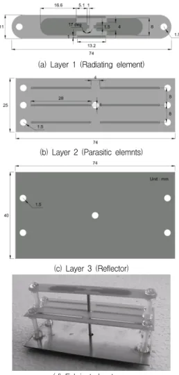
(a) Layer 1 (Radiating element)
(b) Layer 2 (Parasitic elemnts)
(c) Layer 3 (Reflector)
(d) Fabricated antenna
Fig. 1 Configuration of proposed antenna characteristics are required. In addition, for various
applications of WLAN systems, high gain operation of antennas is necessary.
Antennas with an array configuration, phase canceled devices, and partially reflecting surfaces have been studied for high gain operation[7-9].
Generally, high gain operation of a dipole antenna is achieved by a reflector[10]. With use of a reflector, the distance between the radiating element and the reflector should be a quarter wavelength, based on the operating frequency of the radiating element. However, for a dual band dipole antenna, where the distance between the radiating element and the reflector is fixed for lower operating frequency, the distance is more than a quarter wavelength, based on higher operating frequency.
Therefore, the radiation patterns at higher operating frequency become unsuitable for practical application and high gain operation.
In this letter, a WLAN dual band dipole antenna is realized by incorporating open sleeves. For practical application and high gain operation of the radiation patterns at the WLAN dual band, parasitic elements are used. The parasitic elements operate as a director for the lower WLAN band and as a reflector for the higher WLAN band. Details of the antenna design and the experimental results are presented and discussed in subsequent sections.
Ⅱ. Antenna Design
Figure 1 shows the geometry of the proposed antenna. In each layer, a radiating element, parasitic elements, and a reflector are printed on a FR4 substrate with relative permittivity of 4.2 and a thickness of 0.8mm. The radiating element is a planar dipole antenna with open sleeves, as shown in Figure 1(a). For broadband operation, a planar type dipole is used. The length and width of the planar radiating element (with bevel of 17 degrees
and a half circle with a diameter of 8 mm) are 21.7 mm and 8 mm, respectively. In order to situate the open sleeves, a rectangular area (with dimensions of 14.2 mm × 2 mm) is removed. In addition, a rectangular patch (with dimensions of 1 mm × 1.5 mm) is printed to feed the antenna by coaxial cable. The distance between each arm is 2 mm.
For WLAN dual band operation and practical
application of the radiation pattern at high operating
frequency, open sleeves are used. The length and
width of each open sleeve is 13.2 mm and 1 mm,
respectively. The distance between the radiating
element and open sleeves is 2 mm.
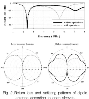
Fig. 2 Return loss and radiating patterns of dipole antenna according to open sleeves For practical application and high gain operation
of the radiation pattern at higher operating frequency, parasitic elements are printed on layer 2, as shown in Figure 1(b). The length and width of each parasitic element is 28 mm and 1mm, respectively. The parasitic elements are configured in a 3 × 2 array. The distance between the radiating element and the parasitic elements is 12.8 mm.
For practical application and high gain operation of the radiation pattern at lower operating frequency, a reflector, which is copper plane, is printed on layer 3, as shown in Figure 1(c). The dimensions of the reflector are 74 mm × 40 mm.
The distance between the radiating element and the reflector is 29.8 mm.
Figure 1(d) shows a photograph of the fabricated antenna. For fixing the structures, plastic bolts and nuts (with a radius of 1.5 mm) are used, as shown in Figure 1(d). Therefore, the holes are situated at the outer part of each layer. The antenna is fed by coaxial cable. For the coaxial cable, center holes on layers 2 and 3 are situated.
Figure 2 shows the return loss and radiation patterns of the dipole antenna with and without open sleeves. When a dipole antenna is fed, current occurs on the surface of the open sleeve by the coupling effect between the radiating element and the open sleeve. The phase of the current on the open sleeve is opposite that of the current of the radiating element. The electrical length of the radiating element is increased by the coupling effect.
Thus, the operating frequency band is decreased.
In the proposed antenna, for the given dimensions, the electrical length of the open sleeve is too short compared with a wavelength of lower operating frequency, and is approximately half wavelength compared with a wavelength of higher operating frequency. Therefore, when the open sleeve is situated, the higher operating frequency is more influenced than the lower operating frequency.
As a result, the higher operating frequency shows
a greater decrease, as presented in Figure 2.
In the case of a high gain antenna using a reflector, for practical application of the radiation patterns, the pattern nulls should be eliminated.
When radiation patterns with pattern nulls are reflected, the influence of the pattern nulls is increased. For a dual band dipole antenna, the radiating element of higher operating frequency is considered as an array of three half wavelength dipole antennas with opposite phases.
The normalized array factor, for a linear array of three isotropic elements with spacing of half wavelength and opposite phases is given by
sin cos
sin cos
(1)
In this case, four pattern nulls appear in the
array factor with 0 < theta < 2π. Therefore, by
pattern multiplication, the total radiation pattern at
higher operating frequency becomes unsuitable for
high gain operation using a reflector. For the given
dimensions, the radiation pattern of the dipole
antenna without open sleeves at higher operating
frequency is shown in Figure 2 (solid line).
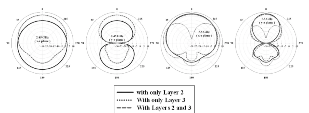
Fig. 3 Radiation patterns of the dipole antenna with various configurations The phase of the current on the open sleeve is
opposite compared with that of the radiating element. The electrical length of the open sleeve is approximately a half wavelength compared with a wavelength at higher operating frequency. Based on higher operating frequency, the current for radiation is canceled by the open sleeve. Therefore, the dipole antenna with open sleeves is considered as an array of two half wavelength dipole antennas with same phase. As a result, unnecessary pattern nulls are eliminated, as shown in Figure 2 (dash line). For lower operating frequency, the electrical length of the open sleeve is too short. Therefore, the radiation pattern is not changed substantially.
For high gain operation of a dipole antenna using a reflector, the distance between the radiating element and the reflector should be a quarter wavelength. However, for a dual band dipole antenna, when the distance between radiating element and reflector is set at a quarter wavelength for lower operating frequency, the distance exceeds a quarter wavelength for higher operating frequency. As a result, in the case of higher operating frequency, the radiation pattern becomes unsuitable for practical application with high gain operation.
The aforementioned problem can be confirmed by the proposed antenna without layer 2. The obtain radiation patterns are shown in Figure 3 (dotted line) for the case when only the reflector (Layer 3)
is equipped, and the distance between the radiating element and the reflector is 29.8 mm. The electrical length of 29.8 mm is approximately 0.55 λ at 5.5 GHz. Therefore, the visible region is expanded by this electrical length. As a result, at 5.5 GHz (higher operating frequency), the pattern null appears. The electrical length of 29.8 mm is approximately 0.25 λ at 2.45 GHz. Therefore, at 2.45 GHz (lower operating frequency), the pattern is appropriate for practical application and high gain operation. To maintain the radiation characteristics at lower operating frequency, and to improve the radiation characteristics at high operating frequency, we used parasitic elements on layer 2. The length and width of each parasitic element is 28 mm and 1 mm, respectively. The distance between the radiating element and the parasitic elements is 12.8 mm. The electrical length of the parasitic element at 2.45 GHz and 5.5 GHz is approximately 0.23 λ and 0.51 λ, respectively. The electrical distance between the radiating element and the parasitic elements at 2.45 GHz and 5.5 GHz is approximately 0.1 λ and 0.24 λ, respectively.
When the parasitic element is capacitive (shorter than 0.5 λ), it operates as a director. On the other hand, when the parasitic element is inductive (longer than 0.5 λ), it operates as a reflector.
Therefore, the parasitic elements operate as a
director at 2.45 GHz and as a reflector at 5.5 GHz.
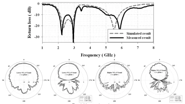
Fig. 4 Measured results The radiation patterns are shown in Figure 3
(solid line) for the case where only parasitic elements (Layer 2) are equipped. Based at higher operating frequency, because the parasitic elements operate as a reflector, the directivity of the antenna is increased in the z direction, and has high gain radiation characteristics. Based at lower operating frequency, because the parasitic elements operate as a director, the directivity of the antenna is increased in the z direction.
When the parasitic elements (Layer 2) and the reflector (Layer 3) are equipped, at 2.45 GHz (lower operating frequency), the increasing directivity in the z direction is reflected by the reflector (Layer 3). Therefore, the effect of the parasitic elements can be ignored. At 5.5 GHz (higher operating frequency), the wave is reflected by the parasitic elements (Layer 2). Therefore, the effect of the reflector (Layer 3) can be ignored. As a result, practical application and high gain operation of the radiation patterns of a dual band dipole antenna are achieved, as shown in Figure 3 (dash line).
Figure 4 shows the measured results regarding
return loss and radiation patterns for the given dimensions. The simulated impedance bandwidths (defined by 10 dB return loss) were 907 MHz (2.111-3.018 GHz) and 674 MHz (5.170-5.844 GHz), respectively. The measured impedance bandwidths (defined by 10 dB on return loss) were 1035 MHz (2.031-3.066 GHz) and 1119 MHz (5.008-6.127 GHz), respectively. In addition, the radiation characteristics of the proposed antenna were measured at 2.4, 2.45, 2.485, 5.15, 5.5, and 5.825 GHz, as shown in Figure. 4.
Good high gain operation of the radiation patterns is observed. The lower WLAN band (2.4-2.485 GHz) has a measured maximum gain of 6.69 dBi and a maximum radiation efficiency of 88.88%, and the higher WLAN band (5.15-5.825 GHz) has a measured maximum gain of 7.81 dBi and a maximum radiation efficiency of 84.07%. Good agreement between the measured and simulated results was observed.
The measured results indicate that the gain is
increased by approximately 4.5 dBi (@ Lower
WLAN band) and 3.3 dBi (@ Higher WLAN band)
compared to only dipole antenna with open sleeves.
Ⅲ. Conclusions
A WLAN dual band dipole antenna with parasitic elements and a reflector for high gain operation is proposed and investigated. Open sleeves, a reflector, and parasitic elements are incorporated in the antenna design for practical application and high gain operation of the radiation patterns, and the resultant radiation characteristics are analyzed. With the parasitic elements, the proposed antenna achieves high gain operation at the WLAN dual band. The proposed antenna with parasitic elements and a reflector has dimensions of 74 mm × 40 mm
× 31.4 mm. The obtained impedance bandwidth (defined by 10dB on return loss) was 1035 MHz (2.031-3.066 GHz) and 1119 MHz (5.008-6.127 GHz), respectively. The measured maximum gain and radiation efficiency were 6.69 dBi and 7.81 dBi, respectively, at each WLAN band.
References
[1] J. Yoon and Y. Choi, "A Design and Implementation of CPW-fed Antenna with Two Branch Strip for WLAN Applications," J.
of the Korea Institute of Electronic Communication Sciences, vol. 10, no. 4, 2015, pp. 441-448.
[2] J. Yoon, "A Design and Implementation of Dual-band Monopole Antenna with two arc-shaped line for WLAN application," J. of the Korea Institute of Electronic Communication Sciences, vol. 12, no. 6, 2017, pp.1049-1056.
[3] Rohith K. Raj, Manoj Joseph, C. K. Aanandan, K. Vasudevan, and P. Mohanan, “A new compact microstrip-fed dual-band coplanar antenna for WLAN applications,” IEEE transactions on antennas and propagation, vol. 54, no. 12, 2006, pp.3755-3762.
[4] J. Yoon, D. Lee, and S. Mun, “A Design and Implementation of Multi-band Monopole Antenna for GPS/WiMAX/WLAN Applications”
J. of the Korea Institute of Electronic Communication Sciences, vol. 10, no. 10, 2015, pp.1189-1196.
[5] J. Yoon, Y. Jang, and Y. Lee, “A Compact Monopole Antenna Design for WLAN/
WiMaX Triple Band Operations”, J. of the Korea Institute of Electronic Communication Sciences, vol. 7, no. 3, 2012, pp.465-473.
[6] G. Kim, “Optimum design of a dual-band patch antenna using the square CSRR construction” J. of the Korea Institute of Electronic Communication Sciences, vol. 12, no.
1, 2017, pp.25-30.
[7] T. J. Judasz, W. L. Ecklund, and B. B.
Balsley, “The coaxial collinear antenna:
current distribution from the cylindrical antenna equation,” IEEE Transactions on Antennas and Propagation, vol. 35, 1987, pp.
327-331.
[8] Gerald R. DeJean and Manos M. Tentzeris,
“A New High-Gain Microstrip Yagi Array Antenna with a High Front-to-Back (F/B) Ratio for WLAN and Millimeter-Wave Applications,” IEEE Transactions on Antennas and Propagation, vol. 55, no. 2, 2007, pp.
298-304.
[9] Yung-Tao Liu, Ting-Chih Tseng, and Kin-Lu Wong, “High-gain printed dipole antenna,”
Microwave and optical technology letters, vol. 46, no. 3, 2005, pp.214-218.
[10] Daoyi Su, Jason J. Qian, H. Yang, and D. Fu,
“A Novel Broadband Polarization Diversity
Antenna Using a Cross-Pair of Folded
Dipoles,” IEEE antennas and wireless propagation
letters, vol. 4, 2005, pp. 433-435.
저자 소개
박성일(Sung-Il Park)
2002년 동신대학교 정보통신공학 과(공학사)
2004년 동신대학교 대학원 정보 통신공학과 졸업(공학석사) 2010년 전남대학교 대학원 전자정보통신공학과 졸업(공학박사)
2014년 ~ 현재 동신대학교 정보통신공학과 조교수
※ 관심분야 : 전자회로설계, RF 부품설계, 이동 통신안테나 설계
정진우(Jinwoo Jung)