A Shared Compliance Control for Application in High Radiation Fields
Sung Ho Ahn, Hoan Sung Jung, Kye Hong Lee, Young Ki Kim, Hark Rho KimDevelopment of Systems for Cold Neutron Source, 150 Deokjin-dong, Yuseong-gu, Daejeon, 305-353 Korea, [email protected]
1. Introduction
Bilateral control systems present a technical alternative for intelligent robotic systems performing dexterous tasks in unstructured environments such as a nuclear facility, outer space and underwater [1][2]. A shared compliance control scheme is proposed for application in high radiation fields in which the force sensor can not be installed because of a radiation effect. A position difference between the master system and the slave system is treated as an equivalent contact force and used for an input to the compliance controller. The compliance controller is implemented by a first order low pass filter and it modifies the position of the master to the reference position. Thus the compliance control task is shared by both the human operator’s direct manual control and the autonomous compliance control of the slave system. Consequently, the position of a slave system tracks well the reference position and the compliance of the slave system is autonomously controlled in a contact condition. The simulation results show the excellence of the proposed scheme.
2. Modeling of 1-DOF bilateral control system
Most bilateral control systems consist of arms with a multiple DOF. However, a 1-DOF system is considered in order to make the problem simpler in this paper.
cop bop mop mm bm bs fs ms τ s τ m cob bob mob object operator slave fm cop bop mop mm bm bs fs ms τ s τ m cob bob mob object operator master fm cop bop mop mm bm bs fs ms τ s τ m cob bob mob object operator slave fm cop bop mop mm bm bs fs ms τ s τ m cob bob mob object operator master fm
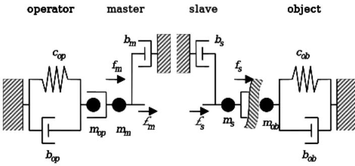
Fig. 1. Bilateral control system.
Fig. 1 shows the schematic diagram of the 1-DOF bilateral control system [3]. The dynamics of the master system and slave system are given by the following equations: m m m m m m+ f =m x&& +b x& τ , (1) s s s s s s− f =m x&& +b x& τ . (2)
where xm and xs denote the displacements of the master and slave systems. And m and m bm represent
the mass and viscous coefficient of the master system respectively, whereas ms and bs are those of the slave system. In addition, fm denotes the force that the operator applies to the master system, and fs denotes the force that it applies to the object. Actuator driving forces of the master and slave systems are represented by τm and τs, respectively. The dynamics of the object interacting with the slave system is modeled by the following linear system:
s ob s ob s ob s m x b x c x f = && + & + (3) where mob,bob , and cob denote the mass, viscous coefficient, and stiffness of the object, respectively. As the displacement of the object is represented by xs in Eq. (3), we assume that the slave system is rigidly contacted with the object or firmly grasping the object, in such a way that it may not depart from the object. It is also assumed that the dynamics of the operator can be approximately represented as a simple spring-damper-mass system: m op m op m op m op− f =m x&& +b x& +c x τ , (4)
where mop,bop , and cop denote the mass, viscous coefficient, and stiffness of the operator respectively, whereas τop means the force generated by an operator’s muscles. Similar to Eq. (3), the displacement of the master system is represented by xm in Eq. (4). We assume that the operator is firmly grasping the master system and he/she never releases the master system during the operation.
3. Proposed Shared Compliance Control
Fig. 2 shows the proposed compliance control scheme. C(s) is designed by considering the position tracking performance of the slave system. Kfr is the force reflection gain by considering the position difference between the reference and the slave system. The autonomous compliance controller, Kc(s) , is
designed by a first order low pass filter and given by
1 ) ( + = s K s K c cc c τ . (5)
Transactions of the Korean Nuclear Society Autumn Meeting Busan, Korea, October 27-28, 2005
xr Kfr + ∆x 1 mss2+bss xs τs fs C(s) _ mobs2+bobs+Cob _ + τd + xm + _ Kc(s) + -xc τm xr Kfr + ∆x 1 mss2+bss 1 mss2+bss xs τs fs C(s) _ mobs2+bobs+Cob _ + τd + xm + _ Kc(s) + -xc τm
Fig. 2. The proposed shared compliance control scheme.
When the slave system contacts on the environment, there is a position difference between the master system and the slave system. An equivalent contact force caused by the position difference between the master system and the slave system is used for the input of the compliance controller. The output of the compliance controller, xc, and the reference position, xr, which is tracked by the slave system, and τ becomes the m following equations.
{
( ) ( )}
) ( ) (s K s x s x s xc = c m − s , (6) ) ( ) ( ) (s x s x s xr = m − c , (7){
( ) ( )}
) (s Kfr xr s xs s m = − τ . (8)Consequently, the reference position which is tracked by the slave system is reduced at the contact condition, and a compliant contact is achieved since the displacement of the slave system is reduced.
4. Simulation Results
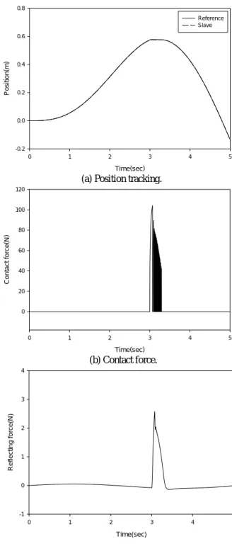
Fig. 3 shows the simulation results for the proposed shared compliance control scheme. It is shown in Fig. 3 (b) that the contact force for the proposed scheme is rapidly reduced after a contact. Consequently, it is concluded that compliance control is obtained using the proposed scheme for the position referenced bilateral control system.
5. Conclusion
A shared compliance control scheme is presented for a position referenced bilateral control system. The proposed scheme can be applied to the compliance control of slave systems located in high radiation fields.
Acknowledgement
This research has been carried out as a part of the nuclear R&D program funded by the Ministry of Science and Technology in Korea.
Time(sec) 0 1 2 3 4 5 Pos itio n (m ) -0.2 0.0 0.2 0.4 0.6 0.8 Reference Slave
(a) Position tracking.
Time(sec) 0 1 2 3 4 5 Cont a c t f o rce(N) 0 20 40 60 80 100 120 (b) Contact force. Time(sec) 0 1 2 3 4 5 Refle c ti ng force(N) -1 0 1 2 3 4 (c) Reflecting force. Fig. 3. Responses for the proposed scheme.
References
[1] S. H. Ahn, J. S. Yoon, & S. J. Lee, A force reflecting control scheme for telemanipulators with high reduction ratio joint, Robotica, 20(1), 2002, 69-79.
[2] S. H. Ahn, J. S. Yoon, & S. J. Lee, A force reflecting and compliant control for heavy-duty power telemanipulators with control input saturation, Journal of the Institute of Electronics
Engineers of Korea, 37(5), 2000, 22-33.
[3] Y. Yokokohji, & T. Yoshikawa, Bilateral control of master slave manipulators for ideal kinesthetic coupling -Formulation and experiment, IEEE Trans. on Robotics and