The Concept of Steam Pressure Control by Changing the Feedwater Flow during Heatup
Operation for an Integral Reactor with a Once-Through Steam Generator
Jae-Kwang Seo, Ki-Yong Choi, Han-Ok Kang ,Young-In Kim, Juhyeon Yoon, Sung-Qunn Zee
Korea Atomic Energy Research Institute, Deokjin-dong 150, Yusung-Gu, Daejon
1. Introduction
The design features of a once-through steam generator (OTSG) for an integral reactor are significantly different from the commercial U-tube type steam generator from several aspects such as the general arrangement, size, operation conditions, and so on. Therefore a sufficient understanding of the thermal-hydraulic characteristics of the OTSG is essential for the design of the nuclear steam supply system (NSSS) and the power conversion system (PCS). It is also necessary to develop operation procedures complying to the unique design features of the OTSG of interest. The OTSG is sized to produce a sufficiently superheated steam during a normal power operation and therefore the secondary system can be simple relative to that of the other types of steam generators. For the plant adopting the OTSG, the steam pressure in the secondary circuit (tube side of the OTSG) is controlled to be constant during a normal power operation. Constant steam pressure is realized by regulating the control valve on the main steam line dedicated for this purpose. However during a heatup operation, at which the fluid state at the exit of the OTSG is a single phase hot water or two phases, it is not proper to use the control valve on the main steam line due to a control problem at low and multi-phase flow conditions and possibly an erosion problem. For these reasons, another dedicated line called a startup cooling line is used during a heatup condition.
There may be several operational conditions for the secondary fluid required to pass through during heatup operation, depending on the design of the PCS. In general, there are two conditions: One is a condition for a vacuum operation for the condenser and another is an entry condition for a steam pressure control operation for an auxiliary power system.
In this study, the concept of using a simple startup cooling line with a fixed flow resistance and changing the feedwater flow for the pressure control of the PCS during a heatup period are contrived. Even though a mathematical model for the startup cooling line itself is not complicated, the working principle of the startup cooling line with a fixed flow resistance, in conjunction with the feedwater flow change, should be confirmed. In order to check that the required passage points are passed through under given plant operational conditions, its thermal-hydraulic performance during a heatup operation is analyzed by using the PZRTR code, which is a computer code developed for the analysis of a heatup operation [1].
The feasibility of the concept of the steam pressure control proposed in this study will be discussed with the results from both of a simulation and an experiment.
2. Methods and Results
The first restriction for the PCS during a heatup operation is assumed to be the condition of a reactor coolant temperature of 180 ℃ and a steam pressure of 0.8 MPa. The second restriction is assumed to be the condition of a reactor coolant temperature of 210 ℃ and a steam pressure of 1.6 MPa.
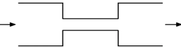
In general, at two-phase flow conditions, a pressure control of the secondary system is known to be difficult. For this reason, the startup cooling device should be designed simply and by not-varying the flow area as much as possible. A simple configuration for the startup cooling line with an orifice is proposed in Figure 1:
Figure 1 Simple device of startup cooling line The proposed startup cooling device (SCD) is a passive component and therefore can not control the pressure of the PCS at a given feedwater flow. Instead, the author proposes the concept of the scheme of changing the feedwater flow at one of two required passage points, that is, the second restriction. With this scheme, the author expects that the before-mentioned two passage restrictions for the PCS operation should be met.
We have to first check that the feedwater flow, calculated from the conventional ∆ P-flow relationship, through the SCD at a given resistance is less than the critical flow at the SCD under the condition of given passage restrictions. Table 1 shows the summary of the critical flow calculations by using Henry-Fauske model.
Table 1 SCD flow v.s. critical flow
T ℃ P MPa x Flow % Critical Flow % ξ near critical flow Case i) 180 0.8 1.012 2.45 4.13 4.6 Case ii) 210 1.6 1.0125 5.0 8.18 4.9
Considering the results of Table 1, we assum that the flow resistance coefficient of the SCD is 13.2. With Transactions of the Korean Nuclear Society Autumn Meeting
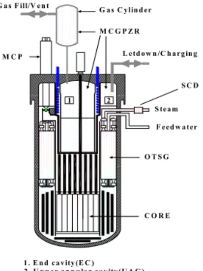
this resistance coefficient, we perform the simulation of a heatup operation using the PZRTR code. The heatup rate of the reactor coolant is assumed to be 100 ℃/h. The feedwater flow rate is 2.5 % of the nominal flow until the reactor coolant temperature reaches 210 ℃/h. At 210 ℃/h, the feedwater flow is increased to 5% of the nominal flow. Figure 2 shows the analysis model for a heatup operation simulation using the PZRTR code. Secondary system is modeled with the proposed simple SCD. Figure 3 shows the behaviors of the secondary parameters during a heatup operation.
S team F eed w ater O T S G M C G P Z R C O R E M C P L etd ow n /C h a rg in g G a s F ill/V en t G a s C ylin d er 1 2 1 . E n d ca v ity (E C ) 2 . U p p er a n n u la r ca v ity(U A C ) S C D
Figure 2 An analysis model for heatup operation simulation using the PZRTR code
0 5000 10000 15000 20000 40 80 120 160 200 240 280 320 T core exit FFW=5 % FFW=2.5 % -0.2 0.0 0.2 0.4 0.6 0.8 1.0 1.2 Psteam ~ 1.8 MPa x PPZR ~ 14.7 MPa Q SG Lsteam L water QSG , L wat e r , Lste a m , Pste a m , x , (no rmali z e d ) Tcore e x it , deg . C Time, sec
Figure 3 analysis results of the behaviors of pressure, temp., quality, and flowrate during heatup operation
The steam pressure and quality during a heatup operation increases gradually as the reactor coolant is being heated up. It is worthwhile to note that the steam temperature is almost the same as the reactor coolant temperature due to the low feedwater flow condition. At the reactor coolant temperature of 180 ℃, superheated steam is produced at the exit of the OTSG and the steam pressure is around 0.8 MPa, which is the operational passage point imposed by the secondary system designer as mentioned. After the feedwater increases at the reactor coolant temperature of 210 ℃, the steam pressure jumps to around 1.6 MPa and the
quality of the steam remains superheated as expected from the static sizing calculation of the SCD. The simulation results clearly show that two operational steam pressures which are required to be passed during a heatup operation are successfully achieved. The results also show that the behavior of the secondary system pressure is controlled well by just a one-step changing of the feedwater flow at a known temperature condition, which means a simplicity and easiness of the relevant operations.
In order to verify the proposed concept of the steam pressure control during a heatup operation, an experimental test was conducted by using the high temp./high pressure test facility-VISTA (Experimental Verification by Integral Simulation of Transients and Accidents) [2].
Figure 4 Steam pressure behavior during heatup operation (feedwater increases at 210 ℃)
Figure 4 shows the results of the experimental heatup simulations from the VISTA. The overall trends of the steam pressure are very similar to the predicted results shown in Figure 3.
3. Conclusion
The concept of using a simple startup cooling line with a fixed flow resistance and changing the feedwater flow for the pressure control of the PCS during a heatup operation is confirmed through a heatup simulation by using the PZRTR code and an experimental test by using the VISTA.
REFERENCES
[1] J. K. Seo, and J. Yoon, Development of a computer code, PZRTR, for the thermal hydraulic analysis of a multi-cavity cold gas pressurizer for an integral reactor, SMART-P, KAER/TR-2632/2003.
[2] K. Y. Choi et al., Experimental report for thermal hydraulic behavior during startup, power change and MCP transient operation by using the high temperature/high pressure test facility (VISTA), KAERI/TR-3020/2005.