Online DCIR Estimation for Series-connected Battery Cells using
Matrix-Switched Capacitor Converter
Phuong-Ha La* and Sung-Jin Choi**
School of Electrical Engineering, University of Ulsan, South Korea
*[email protected], **[email protected]
ABSTRACT
In the battery energy storage system, battery cells are connected in series to increase the operating voltage. Due to the difference in characteristics, the performance degradation of cells is dissimilar. This paper proposes an online DC internal impedance estimation for battery cells in the series string using a matrix-switched capacitor converter, which is already verified as useful for the series balancing of the cells. The simulation in the hardware in the loop test rig shows good accuracy and the feasibility of the proposed method.
Keywords: battery energy storage system, online DC internal impedance, hardware in the loop test rig, series-connected battery, Matrix-switched capacitor converter.
1.
INTRODUCTION
To increase the operating voltage of the battery pack in electric vehicles or energy storage systems, multiple battery cells are connected in series. To ensure safety, the state of charge (SOC) and state of health (SOH) of battery cells are monitored regularly. When the SOC can be assessed by the degradation of battery impedance, the DC Internal Resistance (DCIR) of battery cells is monitored. Various impedance estimation methods are reported in [1], where the methods are classified into offline and online measuring techniques.
In [2, 3], a switched inductor converter is used to inject an AC signal into battery cells and the electrochemical impedance of the battery is estimated. However, it is hard to delimit the impedance value between 2 battery cells. On the other hand, the battery charger is utilized at the end of the charging process to scan the battery impedance [4]. Unfortunately, it only can apply for one battery at the time. To reduce the cost, an online impedance spectroscopy estimation using switched capacitor cell balancing is proposed [5]. Although the accuracy is high, the incurred cost for the voltage and current sensors is its disadvantage.
This paper proposes an online DCIR estimation for series-connected battery cells by utilizing the matrix-switched capacitor equalizer which is suggested in [6]. This paper introduces the operation principle of the DCIR estimation technique in section 2, hardware in the loop test results are performed in section 3, and the conclusion is made in section 4.
2.
PROPOSED METHOD
The proposed method uses one matrix-switched capacitor converter as showing in Fig. 1. Besides, one current sensor and one voltage sensor are used to measure the balancing current and the capacitor voltage, respectively. To discharge the capacitor voltage to zero, a dummy load and a switch are used to discharge the capacitor in the second state of the measuring process. With the matrix-switch, the capacitor can connect with any battery cell in the series string. Based on the measured transferring current and the capacitor voltage, the DCIR of the battery is estimated.
The equivalent circuit of a measuring process is presented in Fig. 2(a) and the switches are controlled by a complementary PWM signal as in Fig. 2(b). The measuring process is divided into two states: measuring state – Phase A (t0 – t1) and
recalibrating state – Phase B (t2 – t3). Between two-state, a small
deadtime period is set to prevent the short-circuit. To analyze
the operation of the circuit, the circuit is transformed to s-domain which is represented in Fig. 3, where R1 is the total
resistance of the loop (on-resistance of the switch, Rd, on, battery
impedance, Rb, and internal resistance of the capacitor, ESR), C
is the capacitance of the measuring capacitor, and Vc is the
voltage of the capacitor. In phase A, switch S1 is turned on while
S2 is kept off. Denote the time constant, τ1, of the switched
capacitor is calculated by (1), where R1 is calculated by (2).
1= R Cx (1) x bx d,on R = R + R + ESR (2) S4H S3H S2H S1H S4L S3L S2L S1L C B1 B2 B3 B4 PWM signal sensor I
Battery Management System SR Rdummy A V sensor V
Figure 1: Matrix-switched capacitor converter
(a) (b) SR t0 t1 t3 t4 T DT DT Deadtime Sx t2 Sx C SR Vb Rx Rdummy
Figure 2: Equivalent circuit: (a) circuit topology; (b) complementary PWM signal. 1 s C I2s 2 ( ) c V t s
R
dummyR
x s C1 0 ( ) c V t s b V s I1s (a) (b)Figure 3: Equivalent circuit in s-domain: (a) Phase A (t0
– t1); (b) Phase B (t2 – t3).
381
The current flowing into the measuring loop, I1s, is
calculated by (3), where the ΔV is the difference between the battery voltage and the initial voltage of the capacitor as in (4).
1 1 1 1 1 1 b c 0 1s x x V -V (t ) V I = R s R s (3) b c 0 V V -V (t ) (4)
By inverse-transforming to the time domain, the transferring current equation becomes (5). Thus, the stored charge in phase A is calculated by (6). 1 ( ) t 1 x V i t e R (5) ( ) 1 1 1 0 -t t t in 1 1 t Q t
i (t)dt VC(1 - e ) (6)Next, the voltage of the capacitor at time t1 can be calculated
by (7), where Vc(t0) is expected to be zero.
1 ( ) (1 ) 1 t in c 1 c 0 Q V t V e V (t ) C (7)
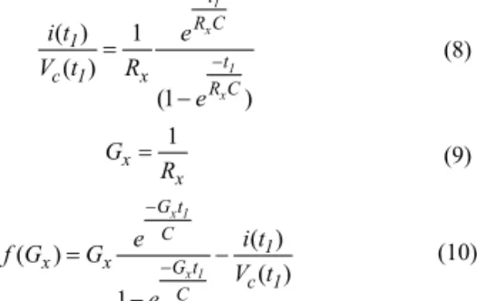
By dividing (5) by (7), a function by R1 is derived as (8).
Denote G as the conductance of the circuit (9), the function becomes (10). ( ) 1 ( ) (1 ) 1 x 1 x t R C 1 t c 1 x R C i t e V t R e (8) 1 x x G R (9) ( ) ( ) ( ) 1 x 1 x 1 G t C 1 x x G t c 1 C e i t f G G V t e (10) By applying the Newton-Raphson method with an initial guess value, the chosen G, which makes the function f(G) become zero, is calculated by (11), where f’(Gx(i)) is the
derivation of f(Gx(i)) and Gx(i) is the i-th iteration value of Gx.
As a result, the DCIR of the battery is calculated by (12).
( ) ( ) x x x ' x f(G (i)) G i +1 = G i -f (G (i)) (11) , 1 ( ) d on x DCIR = R ESR G i +1 (12)
In phase B, the capacitor is discharged by a dummy load, Rdummy. To fully discharge the capacitor, the value of Rdummy is
calculated as (13), where fs is the switching frequency of the
switched capacitor converter.
1 5 dummy s R f C (13)
When the measuring process of one cell is finished, the switching decision is changed to assess the next cell in the string. As a result, the DCIRs of all cells can be estimated.
3.
VERIFICATION OF THE PROPOSED
METHOD
To verify the proposed method, hardware in the loop test for four series-connected 18650 battery cells (3.7V/2.6Ah) has been implemented. Assume that all cells are fully charged but the DCIRs of them are different as in Table I. The capacitance is set at 6800uF, the sum of Rd, on and ESR is set at 100mΩ. Besides,
the Rdummy is set as 20mΩ to discharge the capacitor voltage to zero. The estimated DCIRs of battery cells are summarized in Table I. The results show that the proposed method can estimate the individual DCIR of battery cells within 5.5% tolerance.
4. CONCLUSION
This paper proposes an online DCIR estimation technique based on the matrix-switch capacitor converter for series-connected battery cells. With the matrix-switch structure, the proposed method can estimate the individual DCIR value of battery cells and equalize the energy between cells. The HIL test shows that the tolerance of the method is within 5.5%. A hardware experiment is under preparation for further verifying of the proposed method.
REFERENCE
[1] Koch, R., Kuhn, R., Zilberman, I., et al.: ‘Electrochemical impedance spectroscopy for online battery monitoring – power electronics control’. 2014 16th European Conf. on Power Electronics and Applications (EPE'14-ECCE Europe), Lappeenranta, Finland, 2014, pp. 1–10.
[2] Din, E., Schaef, C., Moffat, K., et al.: ‘A scalable active battery management system with embedded real-time electrochemical impedance spectroscopy’, IEEE Trans. Power Electron., 2016, 32, (7), pp. 5688–5698
[3] Cho, S.-Y., Lee, I.-O., Baek, J.-I., et al.: ‘Battery impedance analysis considering DC component in sinusoidal ripple-current charging’, IEEE Trans. Ind. Electron., 2016, 63, (3), pp. 1561–1573
[4] Thanh-Tuan, N., Van-Long, T., Woojin, C.: ‘Development of the intelligent charger with battery state-off-health estimation using online impedance spectroscopy’. 2014 IEEE 23rd Int. Symp. on Industrial Electronics (ISIE), Istanbul, Turkey, 2014, pp. 454–458
[5] Mina Abedi Varnosfaderani and Dani Strickland, “Online impedance spectroscopy estimation of a dc-dc converter connected battery using a switched capacitor-based balancing circuit,“ The Journal of Engineering, Vol. 2019, Iss. 7, July 2019.
[6] Phuong-Ha La, Hong-Hee Lee, and Sung-Jin Choi, "A Single-Capacitor Equalizer Using Optimal Pairing Algorithm for Series-Connected Battery Cells," 2019 IEEE Energy Conversion Congress and Exposition (ECCE).
TABLE 1: Actual and estimated value of DCIR Cell 1 Cell 2 Cell 3 Cell 4
ACTUAL (mΩ) 34 40 42 50
ESTIMATION (mΩ) 33 38 41 52
ERROR (%) 2.9 5.0 2.4 4.0
Figure 4: Captured waveform of capacitor voltage and current in the measuring process.