Date of publication xxxx 00, 0000, date of current version xxxx 00, 0000. Digital Object Identifier 10.1109/ACCESS.2017.Doi Number
A Cost-Effective 2-Channel OTDM System
Implemented with Sinusoidally Modulated Light
Source
Sunghyun Bae, Student member, IEEE, Jongwoo Park, Seungjun Han, Byung Gon Kim, Minsik Kim, Kyoungsik Yu, Member, IEEE, and Yun C. Chung, Fellow, IEEE
Korea Advanced Institute of Science and Technology (KAIST), 291 Daehak-ro, Yuseong-gu, Daejeon 34141, Korea Corresponding author: Yun C. Chung (e-mail: [email protected]).
This work was supported by IITP grant funded by the Korean government under Grant No. 2017-0-00702..
ABSTRACT We propose to implement a 2-channel optical-time-division-multiplexed (OTDM) system for short-reach optical interconnects by using a sinusoidally modulated light source instead of a complicated mode-locked laser as an input pulse source. In this system, the OTDM signal is obtained by bit-interleaving two optical return-to-zero (RZ) signals generated by using the sinusoidally modulated light. We operate these RZ signals in the orthogonal in-phase and quadrature domains to avoid the unwanted beat components. After the transmission, the OTDM signal is detected by using single photodetector, and then processed by a 22 multiple-input multiple-output equalizer. For a demonstration, we generate 150-Gb/s OTDM signal operating in the 8-level pulse-amplitude modulated (PAM-8) format by using commercial LiNbO3 Mach-Zehnder modulators and transmit this OTDM signal over 1.9 km of the standard single-mode fiber (SSMF). In addition, we fabricate the proposed OTDM transmitter in an integrated silicon-photonics chip and use it to demonstrate the transmission of the 64-Gb/s OTDM PAM-4 signal over 2.2 km of SSMF.
INDEX TERMS optical time-division multiplexing, pulse-amplitude modulation (PAM)
I. INTRODUCTION
Recently, there have been growing interests in the high-speed optical interconnects operating at >100 Gb/s/ to cope with the rapid expansion of data traffic [1]-[7]. However, even with the use of the high-level modulation format, it is difficult to realize such high-speed optical interconnects primarily due to the limited bandwidth of the optical modulator [2]-[6]. We could overcome this problem by using the optical-time-division-multiplexing (OTDM) technology [7]. Since the bandwidth of the photodetector is typically much broader than that of the optical modulator, the OTDM signal can be detected by using single photo-detector. However, for the use of the OTDM technology, it is critical to have a stable optical pulse source with a high repetition rate, high extinction ratio (ER), and narrow pulse width [8]. Previously, an actively mode-locked laser has been commonly used for this purpose [8], [9]. However, it requires a sophisticated control circuitry for the stable operation [10]. There have been some efforts to mitigate this complexity by using a comb generator (typically made of an intensity modulator and a phase modulator) instead of
a mode-locked laser [7], [11]. However, it requires a high-power driving signal (higher than several times of the half-wave voltage of the Mach-Zehnder modulator (MZM), V) and a few hundred meters of dispersion-compensating fiber. In this paper, we propose and demonstrate a 2-channel OTDM transmission system implemented by utilizing a sinusoidally modulated light source (instead of a complicated mode-locked laser) and single photodetector [12], [13]. In our opinion, it is impractical to increase the number of the OTDM channels to be larger than two since the bandwidth of the photodetector is usually not much broader than two times of the modulator’s bandwidth [4], [5]. If we assume that the number of the OTDM channels is limited to two, it would be possible to realize the OTDM transmission system by using a simple sinusoidally modulated light source instead of a mode-locked laser as an optical pulse source. The crosstalk, caused by the use of the sinusoidally modulated light source, can be negated by operating two OTDM channels in the orthogonal in-phase and quadrature (I/Q) domains and using a linear equalizer at the receiver. For a demonstration, we implement a 2-channel OTDM transmission system
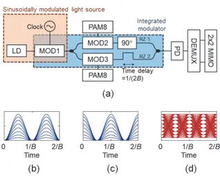
FIGURE 1. (a) A schematic diagram of the proposed 2-channel OTDM transmission system. Optical eye diagrams of (b) RZ1, (c) RZ2, and (d) OTDM signals.
operating at 150 Gb/s by using a sinusoidally modulated light source, two commercial LiNbO3 Mach-Zehnder modulators (MZMs) having a bandwidth of only 17.2 GHz, 8-level pulse amplitude modulation (PAM-8) format, a PIN photodetector having a bandwidth of 70 GHz, and a 22 multiple-input multiple output (MIMO) equalizer. After the transmission of this 150-Gb/s OTDM PAM-8 signal over 1.9 km of the standard single-mode fiber (SSMF), the bit-error rate (BER) is measured to be <3.810-3. In addition, we fabricate the proposed OTDM transmitter in a silicon-photonics (SiP) chip and use it for the transmission of the 64-Gb/s OTDM PAM-4 signal.
II. PROPOSED 2-CHANNEL OTDM SYSTEM
Fig. 1(a) shows a schematic diagram of the proposed 2-channel OTDM transmission system. In the transmitter, we utilize a sinusoidally modulated light source instead of a mode-locked laser as an optical pulse source. For this purpose, a modulator (MOD1) is driven by a sinusoidal signal with a frequency of B. The sinusoidally modulated light is then divided into two parts; in which MOD2 and MOD3 are modulated independently by electrical PAM signals for the generation of two independent optical return-to-zero (RZ) PAM signals. By bit-interleaving these two RZ signals operating at a baud rate of B with a proper time delay (), we can generate an OTDM signal operating at a baud rate of 2B. We operate these RZ signals in the orthogonal I/Q domains to avoid the beat components caused at the symbol transitions during the interleaving process. The transmitted OTDM signal can be detected by using single photodetector. After the detection of this OTDM signal, we demultiplex it and apply a simple 22 MIMO equalizer to mitigate the potential crosstalk arising from the small ER of the sinusoidally modulated light (which is used as an input optical pulse). We believe that the proposed OTDM transmitter can be fabricated cost-effectively by integrating
MOD1~3, an optical phase shifter, and an optical delay line in a SiP chip.
We illustrate the generation of the OTDM PAM-8 signal in Figs. 1(b)~(d). By using the sinusoidally modulated light as the input optical pulse, we generate two independent RZ PAM-8 signals by using two MZMs (i.e., MOD2 and MOD3), as shown in Figs. 1(b) and (c). We assume that the ER of the sinusoidal input light is set to be as high as 20 dB to neglect the crosstalk between two RZ signals. We also assume that MOD2 and MOD3 operate in the linear region (i.e., the amplitude of the driving signal (V) is set to be 0.6V). By combining these two RZ signals, we can generate an equi-spaced OTDM PAM-8 signal shown in Fig. 1(d).
We first evaluate the potential problems of the proposed 2-channel OTDM system by numerical simulations. For this purpose, we assume that (1) the bit rate of the OTDM signal is 150 Gb/s (so that we can compare the results with the experimentally obtained data described in the next section), (2) the signal is modulated with PAM-N (N=2, 4, 8) format, (3) all three MZMs have a sufficient bandwidth for the generation of the 150-Gb/s 2-channel OTDM signal (i.e., 3-dB bandwidth=75/N GHz), (4) two equi-spaced RZ-PAM signals are generated by operating two MZMs in the linear region by setting V=0.6V, (5) the OTDM signal is detected by using a receiver consisted of a PIN photodetector (3-dB bandwidth=150/N GHz, responsivity=1 A/W) and a 50 load resistor operating at 20C, (6) the detected signal is amplified by using an electrical amplifier with a noise figure of 6 dB, and (7) a 22 MIMO equalizer (implemented with symbol-spaced 11-tap feed-forward equalizers (FFEs)) is applied after demultiplexing the OTDM signal. We consider both the thermal and shot noises in these simulations.
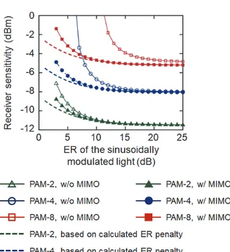
The performance of the proposed 2-channel OTDM system shown in Fig. 1(a) can be affected by the limited ER of the sinusoidally modulated input light. To minimize the crosstalk between two OTDM channels, the large ER of the sinusoidally modulated input light is needed. However, it would inevitably require electrical amplifiers operating at a high frequency with a large output voltage. Thus, we evaluate the effects of the limited ER of the sinusoidally modulated input light on the performance of the proposed 2-channel OTDM transmission system. Fig. 2 shows the receiver sensitivities of the OTDM PAM-N signal (@ BER= 3.810-3) obtained with and without using the 22 MIMO equalizer as a function of the ER of the sinusoidally modulated input light. In this estimation, the ER of the sinusoidally modulated input light is adjusted by changing V of MOD1. In the case when the 22 MIMO equalizer is not applied, the 2-dB power penalty (in comparison with the case when the ER of the sinusoidally modulated input light is set to be 25 dB) is observed for the OTDM PAM-2, PAM-4, and PAM-8 signals when we set the ER to be 6 dB, 9 dB, and 14 dB, respectively. As expected, the signals modulated in the higher-order formats require higher ERs. However, when we apply the 22 MIMO equalizer, the 2-dB power penalty
FIGURE 2. Receiver sensitivities (@BER=3.810-3) of the OTDM PAM-N signals obtained with and without using the 22 MIMO equalizer as a function of the ER of the sinusoidally modulated input light source.
FIGURE 3. The receiver sensitivities estimated as a function of the timing mismatch between two channels (@BER=3.810-3).
is observed for the OTDM PAM-2, PAM-4, and PAM-8 signals at the ER of 5 dB, 5 dB, and 6 dB, respectively. In other words, the receiver sensitivity becomes less affected by the limited ER of the sinusoidally modulated light, since the MIMO equalizer eliminates the crosstalk effectively. We also note that the sinusoidally modulated light having 5-dB ER induces 1.2-dB power penalty even when there is no crosstalk (i.e., the ER of the signal is very high). This is because the small ER of the sinusoidally modulated light (pulse) reduces the ER of the OTDM signal, and the power penalty is expressed as pulse pulse 1 Penalty (dB) 10 log . (1)
In other words, the residual crosstalk only causes ~0.8-dB power penalty when the MIMO equalizer is applied. These results indicate that, with the help of a 22 MIMO equalizer, the proposed 2-channel OTDM system is operable as long as the ER of the sinusoidally modulated input light is set to be >5 dB.
For the proper operation of the proposed 2-channel OTDM system, it is also needed to set the optical delay line placed in the transmitter precisely for the accurate bit-interleaving of two RZ signals. On the other hand, it would be desirable if we can operate the proposed system at slightly different line rates (for example, to utilize various types of the forward-error correction (FEC) code). Although this problem can of course be resolved by utilizing a variable optical delay line, it
would inevitably complicate the proposed system. Thus, we evaluate the effect of the timing mismatch between two RZ signals on the performance of the proposed 2-channel OTDM system. For this purpose, we define the timing mismatch as |TOTDM|/TOTDM, where is the delay time (caused by the optical delay line) and TOTDM is the symbol period of the OTDM signal. Fig. 3 shows the receiver sensitivities estimated as a function of the timing mismatch (@ BER= 3.810-3). In this estimation, the ER of the sinusoidally modulated input light is assumed to be 6 dB. In this case, we cannot achieve the required BER without using the 22 MIMO equalizer. On the other hand, in the case of using the 2x2 MIMO equalizer, we can achieve the required BER even if there is a large timing mismatch. For example, the 1-dB power penalty is observed at the large timing mismatches of 43.8% and 39.1% for the OTDM PAM-4 and PAM-8 signals, respectively. These results indicate that the line rate of the proposed OTDM transmitter can be changed by a factor of 0.72 ~ 1.62 (in the case of using PAM-8 format). Thus, we conclude that the proposed OTDM system is robust against the timing mismatch due to the use of a simple 22 MIMO equalizer.
III. TRANSMISSION EXPERIMENTS
Fig. 4(a) shows the experimental setup to evaluate the performances of the proposed OTDM transmission system implemented by using a sinusoidally modulated light source (instead of an optical pulse source). In this experiment, we generated a 150-Gb/s OTDM PAM-8 signal by using commercial LiNbO3 MZMs (3-dB bandwidth=17.2 GHz). For this purpose, we first modulated the output of a 1.55-m laser by using MZM1 driven with a 25-GHz sinusoidal signal. The ER of the sinusoidally modulated input light was set to be 7.7 dB. For the generation of the 75-Gb/s RZ PAM-8 signal, we modulated the output of MZM1 by using MZM2 with 75-Gb/s electrical PAM-8 signal. The 75-Gb/s electrical PAM-8 signal shown in Fig. 4(c) was obtained by combining three output signals of the 25-Gb/s pulse-pattern
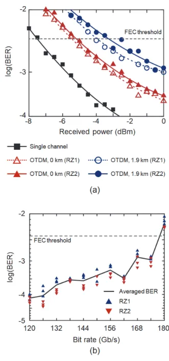
FIGURE 5. (a) Measured BER curves of the 75-Gb/s PAM-8 signal generated without using the OTDM technique and two 75-Gb/s PAM-8 signals demultiplexed from the 150-Gb/s OTDM PAM-PAM-8 signal. (b) Measured BERs of the OTDM PAM-8 signals as a function of the bit rate.
FIGURE 4. (a) Experimental setup to demonstrate the transmission of 150-Gb/s OTDM PAM-8 signal. (b) Measured E/O response of the LiNbO3 MZM used in this experiment. Measured eye diagrams of (c) 75-Gb/s electrical PAM-8 signal, (d) 75-Gb/s optical RZ PAM-8 signal, and (e) 150-Gb/s OTDM PAM-8 signal.
generator (PPG) using a 3-bit digital-to-analog converter (DAC). The complementary outputs of this DAC were used to operate MZM2 in a push-pull configuration. A couple of erbium-doped fiber amplifiers (EDFAs) were used to compensate for the insertion losses of these MZMs. The 25-GHz sinusoidal input light was aligned to the electrical 75-Gb/s PAM-8 signal by using the phase shifter placed in front of MZM1. Fig. 4(d) shows the measured eye diagram of the generated 75-Gb/s RZ PAM-8 signal. As expected, the eye was severely distorted due to the inter-symbol interference caused by the limited modulation bandwidth of MZM2. For the experimental convenience, we generated the 150-Gb/s OTDM PAM-8 signal in Fig. 4(e) by splitting the 75-Gb/s RZ PAM-8 signal into two parts and combining them again after a proper time delay (for the decorrelation and the accurate timing alignment) by using a set of polarization beam splitters (PBSs). Thus, we combined two RZ signals in the orthogonal polarization domains, instead of the I/Q domains. After the 1.9-km long SSMF transmission, the 150-Gb/s OTDM signal was detected by using a PIN photodetector (3-dB bandwidth=70 GHz), amplified by an electrical amplifier, and digitized by a real-time oscilloscope (RTO) at 160 GSample/s. We then demultiplexed this 150-Gb/s OTDM signal into two 75-Gb/s PAM-8 signals and applied a symbol-spaced 22 MIMO equalizer.
Fig. 5(a) shows the measured BER curves of the 150-Gb/s OTDM signal as a function of the received optical power, in comparison with a BER curve of the 75-Gb/s nonreturn-to-zero (NRZ) PAM-8 signal generated by using one MZM (i.e., without using the OTDM technique). The MIMO equalizer applied to the 150-Gb/s OTDM signal compensated for not only the crosstalk but also the limited bandwidth of the MZMs. Thus, for the fair comparison, we also applied FFE for the 75-Gb/s NRZ signal. The number of taps of the FFE was optimized for each case [14]. When
we applied a 6-tap symbol-spaced FFE to this 75-Gb/s signal, its receiver sensitivity was measured to be -7.5 dBm (@ BER=3.810-3). In comparison, in the case of the 150-Gb/s OTDM signal, the sensitivities of two demultiplexed 75-Gb/s RZ PAM-8 signals were measured to be -5.5 dBm and -5.1 dBm, respectively, after applying the MIMO equalizer implemented with 7-tap symbol-spaced FFEs. We expected to observe a power penalty of ~1.5 dB between these signals since the bit rate was doubled. Thus, the additional penalty caused by the OTDM process was estimated to be 0.5~0.9 dB, which was attributed to the
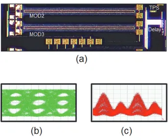
FIGURE 6. (a) A photograph of the proposed OTDM transmitter fabricated in SiP chip. Measured eye diagrams of (b) 32-Gb/s electrical PAM-4 signal and (c) 64-Gb/s OTDM PAM-4 signal.
finite ER of the sinusoidally modulated light, as shown in Fig. 2. From the results in Fig. 5(a), we confirmed that it would be possible to transmit the 150-Gb/s OTDM PAM-8 signal over 1.9 km of SSMF. Fig. 5(b) shows the BER performances of the OTDM PAM-8 signal as a function of the bit rate. In this measurement, we utilized a 22 MIMO equalizer implemented with 11-tap symbol-spaced FFEs. The results showed that we could generate up to 174-Gb/s OTDM PAM-8 signal by utilizing two MZMs having a bandwidth of only 17.2 GHz.
We fabricated the proposed OTDM transmitter in a SiP chip to demonstrate the possibility of integrating it. However, we did not include the modulator used for the generation of the sinusoidally modulated light (i.e., MOD1) in this SiP chip due to its high insertion loss of ~24 dB (which was caused mostly by the grating couplers used to couple the light to and from the SiP chip). Thus, the fabricated chip shown in Fig. 6(a) consisted of only two MZMs (i.e., MOD2 and MOD3), an optical delay line, and a thermal phase shifter (TPS). These MZMs (interaction length: 2 mm, V: 10 V, 3-dB bandwidth: 35 GHz) were designed in a series push-pull (SPP) configuration to have the large bandwidth [15]-[16]. However, the SPP MZM is known to generate the chirped signal [16]. Thus, in case of using the SPP MZMs, it would not be possible to avoid the beat components between two RZ PAM signals completely even if we operate these RZ signals in the orthogonal I/Q domains. Thus, we evaluated the performance of the fabricated SiP chip by transmitting a 64-Gb/s OTDM PAM-4 signal over 2.2 km of SSMF. For this purpose, we first generated a 16-GHz sinusoidal input signal operating at 1.55 m by using a LiNbO3 MZM. The ER of this sinusoidally modulated signal was set to be 10.8 dB. We then obtained the 64-Gb/s OTDM PAM-4 signal by using the fabricated SiP chip. The driving voltage applied to MOD2 and MOD3 was 4 Vp-p. Figs. 6(b) and 6(c) show the eye diagrams of the 32-Gb/s electrical PAM-4 signal applied
to the SPP MZMs and the optical 64-Gb/s OTDM PAM-4 signal generated by using the SiP chip, respectively. The power imbalance between two channels was measured to be 2.2 dB (which was caused by the facts that the two RZ signals traversed different lengths of the waveguides to generate the OTDM signal and the waveguide loss was very high (~6 dB/cm) due to our fab conditions and the metal layer deposited on the delay line for the thermal tuning). Fig. 6(c) showed that this large power imbalance caused a large crosstalk even when the ER of the sinusoidally modulated light was set to be as high as 10.8 dB. After the transmission, the OTDM signal was detected by using a PIN photodetector and then processed by a 22 MIMO equalizer implemented with 5-tap symbol-spaced FFEs. The BERs of the demultiplexed RZ PAM-4 signals were measured to be 2.210-3 and 1.810-3 in the back-to-back condition, and 2.310-3 and 1.610-3 after the transmission over 2.2 km of SSMF. From these results, we confirmed that it would be possible to fabricate the proposed OTDM transmitter in a SiP chip using the SPP MZMs.
IV. SUMMARY
We have proposed to overcome the bandwidth limitation of the optical modulator by using a simple OTDM technique. We assumed that the number of the OTDM channels should be limited to two, considering the realizable bandwidth of the photodetector. Thus, we could implement the 2-channel OTDM transmission system by using a simple sinusoidally modulated light source instead of the complicated mode-locked laser. The potential problems arising from the use of the sinusoidally modulated input light, such as the low ER and crosstalk between channels, could be mitigated by using a simple 22 MIMO equalizer at the receiver. We also found that, due to the use of the MIMO equalizer, the proposed OTDM system was very robust against the timing mismatch between channels. To demonstrate the technical feasibility of the proposed OTDM system, we generated a 150-Gb/s OTDM PAM-8 signal by using LiNbO3 MZMs having 3-dB bandwidth of only 17.2 GHz, and successfully transmit it over 1.9 km of SSMF. This result indicated that the proposed OTDM technique could be used for the generation of the high-speed PAM signal operating at the speed ~9 times faster than the bandwidth of the modulators. In addition, we fabricated the proposed 2-channel OTDM transmitter in a SiP chip (except the modulator used for generating the sinusoidally modulated input light) and used it for the transmission of the 64-Gb/s OTDM PAM-4 signal over 2.2 km of SSMF. We believe that the proposed 2-channel OTDM system utilizing the sinusoidally modulated input light (instead of the mode-locked laser) could help the development of the short-reach optical interconnects operating at the speed faster than 200 Gb/s.
REFERENCES
[1] The homepage of IEEE P802.3bs 400 Gb/s Ethernet Task Force, http://www.ieee802.org/3/bs/
[2] J. Shi, J. Zhang, N. Chi, and J. Yu, “Comparison of 100G PAM-8, CAP-64 and DFT-S OFDM with a bandwidth-limited direct-detection receiver,” Opt. Express, vol. 25, no. 26, pp. 32254-32262, Dec. 2017. [3] Q. Cheng, M. Bahadori, M. Glick, S. Rumley, and K.
Bergman, “Recent advances in optical technologies for data centers: a review,” Optica, vol. 5, no. 11, pp. 1354-1370, Nov. 2018.
[4] S. Lange, S. Wolf, J. Lutz, L. Altenhain, R. Schmid, R. Kaiser, M. Schell, C. Koos, and S. Randel, “100 GBd intensity modulation and direct detection with an InP-based monolithic DFB laser Mach-Zehnder modulator,” J. Lightw. Technol., vol. 36, no. 1, pp. 97-102, Jan. 2018. [5] J. Zhang, J. Yu, L. Zhao, K. Wang, J. Shi, X. Li, M. Kong, W. Zhou, X. Pan, B. Liu, X. Xin, L. Zhang, and Y. Zhang, “Demonstration of 260-Gb/s single-lane EML-based PS-PAM-8 IM/DD for datacenter interconnects,” in Proc. Optical Fiber Communication Conference and Exhibition, San Diego, CA, USA, 2019, paper W4I.4.
[6] S. Bae, B. G. Kim, and Y. C. Chung, “Generation of high-speed PAM4 signal by overdriving two Mach-Zehnder modulators,” OSA Continuum, vol. 2, no. 2, pp. 486-494 Feb., 2019.
[7] J. Verbist, M. Vanhoecke, M. Lillieholm, S. Srinivasan, P. Heyn, J. Campenhout, M. Galili, L. Oxenlowe, X. Yin, J. Bauwelinck, and G. Roelkens, “4:1 silicon Photonic serializer for data center interconnects demonstrating 104 Gbaud OOK and PAM4 transmission,” J. Lightw. Technol., vol. 37, no. 5, pp. 1498-1503, Mar. 2019.
[8] H. Weber, R. Ludwig, S. Ferber, C. Langhorst, M. Kroh, V. Marembert, C. Boerner, and C. Schubert, “Ultrahigh-speed OTDM-transmission technology,” J. Lightwave Technol., vol. 24, no. 12, pp. 4616-4627, Dec. 2006. [9] S. Kawanishi, “Ultrahigh-speed optical
time-division-multiplexed transmission technology based on optical signal processing,” IEEE. J. Quantum Electron., vol. 34, no. 11, pp. 2064-2079, Nov. 1998.
[10] Y. Ji, Y. Li, J. Wu, F. Zhang, K. Xu, W. Li, X. Hong, and J. Lin, “A phase stable short pulses generator using an EAM and phase modulators for application in 160-Gbaud QPSK systems,” IEEE Photonics Technol. Lett., vol. 24, no. 1, pp. 64–66, Jan. 2012.
[11] T. Otsuji, M. Yaita, T. Nagatsuma, and E. Sano, “10-80-Gb/s highly extinctive electrooptic pulse pattern generation,” J. Sel. Top. Quantum Electron., vol. 2, no. 3, pp. 643-649, Sep. 1996.
[12] Y. C. Chung, S. Bae, B. G. Kim, and M. S. Kim, “Optical transmission system utilizing optical-time-division-multiplexed signals generated by using the sinusoidally modulated light,” KR Patent, application no.10-2019-0092208, July 30, 2019.
[13] S. Bae, B. G. Kim, M. S. Kim, and Y. C. Chung, “Practical multiplexing techniques for next-generation data center network,” in Proc. International Conference on Transparent Optical Networks, Bari, Italy, 2020, paper Tu.A.3.1.
[14] K. Y. Cho, Y. Takushima, and Y. C. Chung, “10-Gb/s operation of RSOA for WDM PON,” IEEE Photonics Technol. Lett., vol. 20, no. 18, pp. 1533–1535, Sep. 2008.
[15] P. Dong, L. Chen, and Y. Chen, “High-speed low-voltage single-drive push-pull silicon Mach-Zehnder modulators,” Opt. Express, vol. 20, no. 6, pp. 6163-6169, Feb. 2012.
[16] A. Samani, V. Veerasubramanian, E. El-Fiky, D. Patel, and D. Plant, “A silicon photonic PAM-4 modulator based on dual-parallel Mach-Zehnder interferometers,” IEEE Photon. J., vol. 8, no. 1, p. 7800610, Feb. 2016.