Polyol Synthesis of Ruthenium Selenide Catalysts for Oxygen Reduction Reaction
††Ki Rak Lee and Seong Ihl Woo*
Department of Chemical and Biomolecular Engineering (BK21 Graduate Program),
Korea Advanced Institute of Science and Technology, Daejeon 305-701, Korea. *E-mail: [email protected] Received July 14, 2010, Accepted September 30, 2010
Ruthenium catalysts modified by selenium have been introduced as alternative materials to Pt in Direct methanol fuel cells (DMFCs). RuSe nano-particles were synthesized on the Vulcan XC72R carbon supports via polyol method. The prepared catalysts were electrochemically and physically characterized by cyclic voltammetry (CV,) linear sweep voltammetry, methanol tolerance test, X-ray diffraction (XRD), Transmission electron microscopy (TEM), Energy- dispersive Spectrometer (EDS) and X-ray photoelectron spectroscopy (XPS). Increasing the Se concentration up to 20 at % increased the electro-catalytic activity for the oxygen reduction. By increasing Se amount, Ru metallic form on the surface was increased. The Ru80Se20/C catalysts showed the highest oxygen reduction reaction (ORR) activity
and outstanding methanol tolerant property in half cell tests as well as single cell test.
Key Words: Ruthenium-chalcogenide, Fuel cell, Oxygen reduction reaction, Electro-catalysts, Methanol
tol-erant property
Introduction
DMFCs are becoming promising power sources to substitute fuel combustion energies as well as batteries in portable electro-nic devices.1-5 Significant and intensive investigations in this field have been progressed to commercialize this device. Until now, all low-temperature fuel cells including DMFCs have used platinum or platinum based materials as the electrode. PtRu alloy catalysts are widely used as the anode material.6,7 In the cathode, platinum shows an outstanding performance for oxy-gen reduction such as the highest catalytic activity and stability. Its high cost, however, is a serious problem. This problem has to be solved for successful commercialization. To solve the economic problem, Pt-transition metal alloy materials such as PtNi,8,9 PtCo,10,11 and PtCr12 are developed as ORR catalysts. Furthermore, ternary or quaternary Pt based catalysts13,14 and Pt nano-particles with new support materials15-17 are introduced. These materials show the improved ORR activity because pre-vention of the particle sintering, surface roughening from the removal of some alloy metal, proper crystallographic geometry, and change of Pt-Pt inter-atomic distance causing change of Pt electro binding energy.18,19 Amounts of platinum, however, are still needed and it is not enough. Furthermore, platinum based catalysts show low methanol tolerance property. It is not suit-able for the cathode material in DMFCs. Amount of methanol crossover generally occurs from the anode to cathode in DMFCs. Methanol crossover is the main reason for the drop in perfor-mance in the cathode.20,21 Development of economic catalysts with high ORR activity and methanol tolerant property is needed. Recently, many researchers have interested in the develop-ment of Pt-free materials for oxygen electro-reduction. Efforts have been made to develop the non-platinum ORR catalysts such as Pd alloy matertials,22-24 transition-metal macrocyclic compounds,25,26 Ru based materials,14,27,28 and N doped carbon
†This paper is dedicated to Professor Hasuck Kim for his outstanding
contribution to electrochemistry and analytical chemistry.
materials.29-31 The approach of non-Pt catalysts not only makes fuel cells economical but also clears methanol crossover pro-blem. Among various non-Pt catalysts, Ru based catalysts show good catalytic activity in ORR and high selectivity for four- electron reduction of oxygen to water in acidic media. The Ru based chalcogenides can be divided into Chevrel phases32 and amorphous ruthenium chalcogenides.33 The former shows good performance as a cathode material. They are generally prepared by solid-state reaction in high temperature and pressure which is very complicated and expensive. The latter shows efficient activity for ORR in acidic media at low temperatures.
In this study, the Ru-chalcogenide (RuSe) nano-particles were synthesized on the carbon support via polyol method and an optimum composition was found. Polyol reduction is a well known process for synthesizing metallic nanoparticles.34 For comparison, Ru/C was prepared with the same process. The prepared RuSe/C catalysts were tested for electro-chemical studies in half-cells as well as in single cells, and physical cha-racterizations were carried out by XRD and XPS.
Experimental
RuSe nano particles were deposited on Vulcan XC72R using ethylene glycol as a reducing agent via polyol process.35 Ruthe-nium acetylacetonate and seleRuthe-nium tetrachloride were dissolved in ethylene glycol and then Vulcan XC72R was added to the solution. The suspension was sonicated and stirred for 1 h under N2 condition. The suspension was then refluxed at 160 oC under N2 condition with continuous stirring for 4 h. After the reflux, the suspension was filtered and washed with DI water and ethanol. Finally, the catalysts were dried at 80 oC, overnight. The prepared catalysts are notated as Ru/C, Ru95Se5/C, Ru90Se10/C, Ru85Se15/C, Ru80Se20/C, and Ru75Se25/C to their atomic com-position ratios. The RuxSe100-x/C notation means a prepared ratio. Loading of metals was 60 wt %. All chemicals were anal-ytical grade or better and were purchased from Sigma-Aldrich.
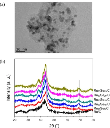
(a) 20 30 40 50 60 70 80 2θ (o) Inte nsity ( a. u. ) (b) Ru75Se25/C Ru80Se20/C Ru85Se15/C Ru90Se10/C Ru95Se5/C Ru/C
Figure 1. TEM image of the Ru80Se20/C catalyst (a) and XRD results
of the Ru/C, Ru95Se5/C, Ru90Se10/C, Ru85Se15/C, Ru80Se20/C, and
Ru75Se25/C catalysts (b).
XRD analysis was performed using a Cu Kα radiation with a D/MAX-IIIC diffractometer for characterization of structural properties of the powder catalysts. XPS measurements were performed using Al Kα radiation and the constant pass energy of 25 eV. The XPS peak software version 4.1 was used, and spectral peaks were fitted using a mixed Gaussian-Lorentzian (80:20) line and Shirley baselines. TEM analysis was done on a field emission transmission electron microscope (Tecnai G2 F30 S-Twin). EDS analysis was carried out using a field emi-ssion SEM (Nova230) at an acceleration voltage of 20 kV.
Electrochemical analysis was carried out in a three electrode cell with a platinum counter electrode, an Ag/AgCl reference electrode (BAS Co., Ltd., MF-2052 RE5B), and a glassy carbon working electrode (3 mm dia, BAS Co., Ltd., MF-2012). The working electrodes were prepared by the thin-film electrode method36 and had a loading of 80 μg catalyst. The prepared elect-rodes were tested for CV and linear sweep voltammetry tests. The CV test was performed between 0.0 and 0.8 V (vs. reference hydrogen electrode (RHE)) at a scan rate of 15 mV s‒1. Nitro-gen purged 1 M HClO4 solution was used as an electrolyte. The linear sweep voltammetry was performed by rotating the work-ing electrodes at a scan rate of 5 mV s‒1 in oxygen saturated 1 M HClO4 solution and in oxygen saturated 1 M HClO4 + 0.1 M methanol solution, respectively. All electrochemical experi-ments were carried out at room temperature and at ambient pressure. All potentials in this study were converted to RHE scale.
The membrane electrode assemblies (MEAs) were fabricated by spraying the catalyst onto Nafion 112, The anode catalyst was PtRu/C (E-tek, 60 wt %, Pt:Ru = 1:1 atomic ratio) and the cathode catalyst was Pt/C (E-tek, 60 wt %) and Ru80Se20/C. The catalyst loading was 2.5 mg cm‒2. The catalyst-coated mem-branes were hot-pressed at 120 oC for 3 min. Polarization curves were obtained using a homemade single cell with an active area of 4 cm2. 1 M methanol and oxygen were fed into the anode and cathode at the flow rate of 1 mL min‒1 and 100 cc min‒1, respectively. The single cells were operated at 70 oC.
Results and Discussions
Fig. 1(a) shows a TEM image of the Ru80Se20/C catalyst. There are nano sized metal particles on the carbon support. However, a non-homogeneous particle distribution is observed due to the high RuSe loading. Reliable analysis of the particle size is difficult from TEM image. The particle size of each catalysts was calculated from XRD analysis. XRD results of the synthesized catalysts are shown in Fig. 1(b). The broad peak at 2θ value of 25o was related to (002) plane of the hexagonal structure of Vulcan XC-72R carbon support.37 Selenium or selenide phase was not detected in XRD results. It is the reason that the selenium is present in the form of a fully amorphous phase or the amount of crystalline selenium is below the XRD sensitivity.38 The (110) diffraction peak of crystallographic Ru plane was used for analysis of the structural properties. The (110) peaks were observed at 2θ values of 69.40o for Ru/C, 69.40o for Ru95Se5/C, 69.42o for Ru90Se10/C, 69.45o for Ru85Se15/C, 69.50o for Ru80Se20/C, and 69.50o for Ru75Se25/C, respectively. The (110) peaks of the synthesized catalysts
appe-ared at similar 2θ values, indicating the low degree of alloy in most catalysts. The average particle sizes were calculated using the Debye-Scherrer equation.39 Average particle sized were 4.9, 5.1, 3.9, 3.6, 4.1, and 4.6 nm for the Ru/C, Ru95Se5/C, Ru90Se10/C, Ru85Se15/C, Ru80Se20/C, and Ru75Se25/C, respec-tively. The EDS data showed the purposed bulk compositions of Ru and Se on each catalyst. However, selenium was not detected from XRD analysis. It means that the Se forms an amorphous phase on the RuSe catalysts. A summary of the XRD and EDS results are listed in Table 1.
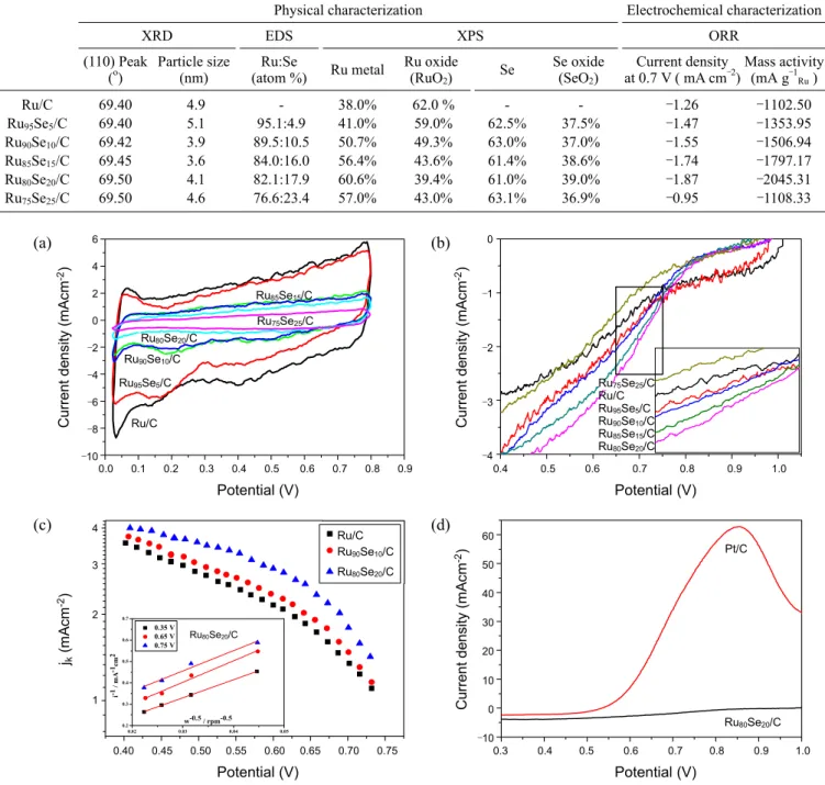
Electrochemical analysis of the synthesized catalysts is shown in Fig. 2. Fig. 2(a) shows CV results of the Ru/C and Ru100-xSex/C catalysts. With Ru/C catalyst in the range 0 - 0.2 V, an anodic peak was attributed to hydrogen desorption from Ru surface.40,41 In the region 0.2 - 0.8 V, an increasing anodic cur-rent was detected due to the ruthenium surface oxidation and ad-sorption of water related species, such as the hydroxyl group.42,43 The cathodic peak around 0.2 V was caused by reduction of oxidized Ru surface and adsorption of hydrogen on Ru sur-face.44-46 Increasing Se amount in the catalysts, however, the hydrogen adsorption peak is significantly suppressed, indicating that Ru surface was modified by Se. Furthermore, increasing Se amount, Ru oxidation peaks were significantly suppressed. It was reported that Se stabilized Ru surface against oxidation.47 Following the CV studies, we conducted ORR measurements (Fig. 2(b)). For a comparison, Pt/C (E-tek, 60 wt %) is also measured. Current densities at 0.7 V were ‒1.26, ‒1.47, ‒1.55, ‒1.74, ‒1.87, ‒0.95 and ‒2.23 mA cm‒2 for the Ru/C, Ru95Se5/C, Ru90Se10/C, Ru85Se15/C, Ru80Se20/C, Ru75Se25/C, and Pt/C. In the Ru based catalysts, the Ru80Se20/C catalyst showed the
Ru75Se25/C Ru80Se20/C Ru85Se15/C Ru90Se10/C Ru95Se5/C Ru/C 0.0 0.1 0.2 0.3 0.4 0.5 0.6 0.7 0.8 0.9 Potential (V) C urre nt d en sit y (m A cm -2) (a) 6 4 2 0 ‒2 ‒4 ‒6 ‒8 ‒10 Ru80Se20/C Ru90Se10/C Ru/C Ru85Se15/C Ru75Se25/C Ru95Se5/C Ru95Se5/C Ru75Se25/C Ru80Se20/C Ru85Se15/C Ru90Se10/C Ru/C 0.4 0.5 0.6 0.7 0.8 0.9 1.0 Potential (V) C urre nt d en sit y (m A cm -2) (b) 0 ‒1 ‒2 ‒3 ‒4 Ru75Se25/C Ru/C Ru95Se5/C Ru90Se10/C Ru85Se15/C Ru80Se20/C 0.02 0.03 0.04 0.05 0.2 0.3 0.4 0.5 0.6 0.7 0.35 V 0.65 V 0.75 V i-1 / mA -1cm 2 w-0.5 / rpm-0.5 Ru/C Ru90Se10/C Ru80Se20/C Ru80Se20/C 0.40 0.45 0.50 0.55 0.60 0.65 0.70 0.75 Potential (V) jk (m A cm -2) (c) 4 3 2 1 Ru80Se20/C Ru/C Ru90Se10/C Ru80Se20/C Ru80Se20/C Pt/C 0.3 0.4 0.5 0.6 0.7 0.8 0.9 1.0 Potential (V) C urre nt d en sit y (m A cm -2) (d) 60 50 40 30 20 10 0 ‒10 Pt/C Ru80Se20/C
Figure 2. Electrochemical characterization; Cyclic voltammetry results (a) and ORR results (b) for the Ru/C, Ru95Se5/C, Ru90Se10/C, Ru85Se15/C,
Ru80Se20/C, and Ru75Se25/C catalysts. Tafel plots for the ORR of Ru/C, Ru90Se10/C, and Ru80Se20/C catalysts (c). Methanol tolerance results for
the Ru80Se20/C catalyst (d).
Table 1. Summary of physical and electrochemical properties of the Ru/C, Ru95Se5/C, Ru90Se10/C, Ru85Se15/C, Ru80Se20/C, and Ru75Se25/C
catalysts
Physical characterization Electrochemical characterization
XRD EDS XPS ORR
(110) Peak
(o) Particle size(nm) (atom %)Ru:Se Ru metal Ru oxide(RuO
2) Se
Se oxide (SeO2)
Current density
at 0.7 V ( mA cm‒2)Mass activity(mA g‒1 Ru ) Ru/C 69.40 4.9 - 38.0% 62.0 % - - ‒1.26 ‒1102.50 Ru95Se5/C 69.40 5.1 95.1:4.9 41.0% 59.0% 62.5% 37.5% ‒1.47 ‒1353.95 Ru90Se10/C 69.42 3.9 89.5:10.5 50.7% 49.3% 63.0% 37.0% ‒1.55 ‒1506.94 Ru85Se15/C 69.45 3.6 84.0:16.0 56.4% 43.6% 61.4% 38.6% ‒1.74 ‒1797.17 Ru80Se20/C 69.50 4.1 82.1:17.9 60.6% 39.4% 61.0% 39.0% ‒1.87 ‒2045.31 Ru75Se25/C 69.50 4.6 76.6:23.4 57.0% 43.0% 63.1% 36.9% ‒0.95 ‒1108.33
est ORR activity which was 84% of the activity of the Pt/C. Activity of the Ru80Se20/C catalyst was higher by 33% than that of the Ru/C. The mass activities were calculated from the current densities. The mass activity of the Ru80Se20/C (‒2045.31 mA g‒1Ru) showed also the highest activity in the RuSe catalysts. The mass activity of Ru80Se20/C was almost twice as large as that of the Ru/C. The above observations, optimum concentra-tion of RuSe composiconcentra-tion was the Ru80Se20/C which is similar with a previous study. Bron et al. suggested Ru85Se15 composi-tion as the optimum concentracomposi-tion.48 This difference is caused
by difference surface features such as amounts of Ru metal and Ru oxide originated from synthesis process. Se modified Ru catalysts showed the improved ORR activity which has been related to chemical stabilization of metallic Ru surface against oxidation.49 Babu et al. reported that Se on the Ru surface existed as metallic form due to charge transfer from Ru to Se.50 This charge transfer prevents the oxidation of Ru surface. In Fig. 2(c), the kinetic currents are calculated using the Koutecky- Levich (K-L) equation and Tafel plots. The RDE data are anal-yzed using the K-L equation:
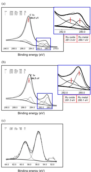
(a) C 1s 284.5 eV Ru oxide 281.3 eV Ru metal 280.1 eV 290.0 288.0 286.0 284.0 282.0 280.0 278.0
Binding energy (eV)
282.0 280.0 Ru oxide 281.3 eV Ru metal280.1 eV (b) C 1s 284.5 eV Ru oxide 281.3 eV Ru metal 280.1 eV 290.0 288.0 286.0 284.0 282.0 280.0 282.0 280.0 Ru oxide 281.3 eV Ru metal280.1 eV
Binding energy (eV)
(c)
64.0 62.0 60.0 58.0 56.0 54.0 52.0
Binding energy (eV)
Figure 3. The XPS spectra of the Ru95Se5/C and Ru80Se20/C: Ru 3d
regions for the Ru95Se5/C (a) and the Ru80Se20/C (b) catalysts and Se
3d region for the Ru80Se20/C (c). 1/2
k D k
1 1 1 1 1
= + = +
j j j j Bω (1)
Where j is the measured current density, jk is the kinetic current density, jD is the diffusion-limited current density, ω is the rotation rate of the electrode and B is the Levich constant. The value of the B can be obtained from the slope of the K-L plot. The calculated kinetic currents jk of Ru/C, Ru90Se10/C and Ru80Se20/C are displayed in semi-logarithmic plots versus the potential E. The corrected jk of three catalysts are compared at 0.7 V. The kinetic current densities at 0.7 V were 1.34, 1.47 and 1.80 mA cm‒2 for the Ru/C, Ru90Se10/C and Ru80Se20/C.
The Ru80Se20/C catalyst showed the highest kinetic activity. As shown in the Tafel plot, Se modification of the Ru surface leads to increasing the catalytic activity of the Ru catalyst. The Ru80Se20/C catalyst showed significantly high methanol tole-rant property compared to the Pt/C (Fig. 2(d)). The current den-sity under methanol environment of Ru80Se20/C catalyst was ‒1.82 mA cm‒2, which is 97.3% performance of the activity without methanol. It is the reason that Ru catalyst has almost no methanol oxidation property. The high methanol property make Ru80Se20/C a powerful candidate as a cathode material of DMFCs. A summary of the electrochemical analysis results is tabulated in Table 1.
Fig. 3 exhibits the XPS results of Ru 3d core level for Ru95Se5/C (Fig. 3 (a)) and Ru80Se20/C (Fig. 3(b)). The results of all catalysts for Ru 3d core level are summarized in Table 1. The prepared catalysts were supported by Vulcan XC72R carbon material which shows the large C 1s peak in 284.5 eV. The metallic Ru doublet with 3d5/2 and 3d3/2 components shows peaks at 280.1 eV and 284.3 eV, respectively.51 From peak deconvolution, the Ru surface was composed of a metallic Ru and an oxide form. The RuO2 doublet with 3d5/2 and 3d3/2 components exhibit peaks at 281.3 eV and 285.5 eV, respectively.52,53 The ratios of the metallic Ru to RuO2 were calculated from the area of the 3d5/2 peaks. The Ru/C catalyst was composed of 38% metallic Ru and 62% RuO2. With increased Se amounts, amounts of metallic Ru on the catalysts surfaces were increased up to 60.6% on the Ru80Se20/C surface. In the case of Ru75Se25/C catalysts, similar surface composition with Ru80Se20/C was observed. It has good agreement with previous study. As mentioned above, Se modi-fication on Ru surface makes Ru surface metallic. Lewera et al. suggested that the oxygen in the Ru surface is strongly bonded to Ru, and Se is weakening the Ru-O bond.54 In Fig. 3(c), the XPS result of Se 3d core level for Ru80Se20/C is exhibited. The results of all catalysts for Se 3d core level are summarized in Table 1. The binding energy peak for Se 3d3/2 peak appear at 55.2 eV. The Se 3d3/2 peak for oxidized form appears at about 58.5 - 59.0 eV.52,53 The Ru80Se20/C catalyst was composed of 61.0% elemental Se and 39.0% oxidized Se. Other catalysts show similar results to Ru80Se20/C. All catalysts appeared the large amount of oxidized Se. In a previous study, Zhu et al. reported that elemental Se powder were synthesized by polyol method in similar conditions.55 It means that reduction of the Se was affected by the Ru species. The oxidized Se on the RuSe catalysts should be affected by the charge transfer from Ru to Se on Se modified Ru surface.
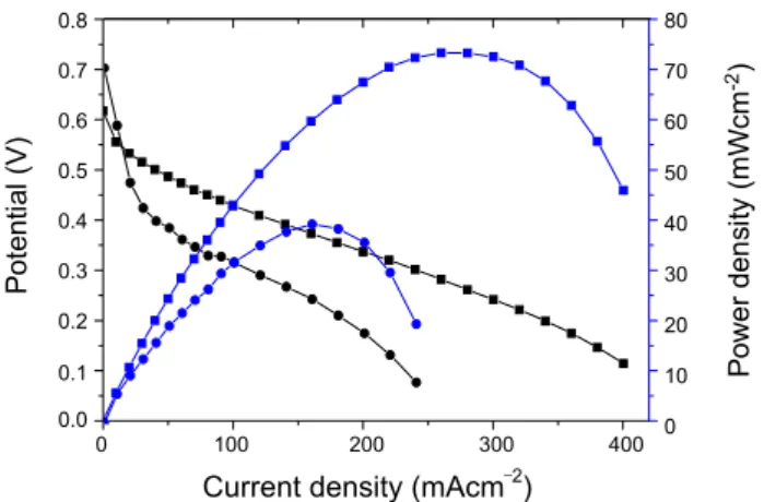
Fig. 4 shows the single cell performance of Ru80Se20/C catal-yst. The commercial Pt/C was prepared for comparison. MEA1 was composed of PtRu/C (anode) and Pt/C (cathode) and MEA2 was composed of PtRu/C (anode) and Ru80Se20/C (cathode). The open circuit voltages (OCV) of MEA1 and MEA2 were 0.62 V and 0.70 V, respectively. The MEA2 showed improved OCV due to outstanding methanol tolerant property of Ru80Se20/C which is exhibited in electrochemical study. As expected, MEA1 showed much higher max power density, 73.5 mW cm‒2 than MEA2. Max power density of MEA2 was 39.5 mW cm‒2. The Ru80Se20/C which is non-Pt cathode material showed 53.6% max power density and the improved OCV when comparing with Pt/C. This is suitable for cathode material to substitute Pt but the improved ORR activity of RuSe catalysts is essential.
0 100 200 300 400 Current density (mAcm‒2)
0.8 0.7 0.6 0.5 0.4 0.3 0.2 0.1 0.0 Po te nt ia l ( V ) 80 70 60 50 40 30 20 10 0 P ow er d en si ty (mW cm -2)
Figure 4. The single cell performances for MEA1 (■, anode : PtRu/C,
cathode : Pt/C) and MEA2 (●, anode : PtRu/C, cathode : Ru80Se20/C)
in DMFC.
Conclusions
The Se modified Ru catalysts were synthesized via a polyol method. By adding Se component, amounts of metallic Ru sur-face were increased and improvement of ORR activity was achieved. Optimum concentration of RuSe composition was the Ru80Se20/C which is almost twice as higher than Ru/C in mass activity. Furthermore, the Ru80Se20/C showed prominent me-thanol tolerant property. Electrochemical characterization and single cell measurement showed that the Ru80Se20/C is suitable for cathode material of DMFCs.
Acknowledgments. This work was supported by the Korea
Science & Engineering Foundation (KOSEF) grant (WCU pro-gram, 31-2008-000-10055-0) funded by the Ministry of Edu-cation and Science & Technology (MEST) and the National Re-search Foundation of Korea(NRF) grant funded by the MEST (No. 2009-0092783).
References
1. Jeon, M. K.; Lee, K. R.; Oh, K. S.; Hong, D. S.; Won, J. Y.; Li, S.; Woo, S. I. J. Power Sources 2006, 158, 1344.
2. Choi, W. C.; Kim, J. D.; Woo, S. I. Catal. Today 2002, 74, 235. 3. Jeon, M. K.; Won, J. Y.; Woo, S. I. Electrochem. Solid-State Lett.
2007, 10, B25.
4. Choi, W. C.; Kim, J. D.; Woo, S. I. J. Power Sources 2001, 96, 411. 5. Antolini, E. Appl. Catal. B: Environ. 2007, 74, 337.
6. Lee, K. R.; Jeon, M. K.; Woo, S. I. Appl. Catal. B-Environ. 2009, 91, 428.
7. Jeon, M. K.; Lee, K. R.; Jeon, H. J.; Woo, S. I. J. Appl. Electro-chem. 2009, 39, 1503.
8. Travitsky, N.; Ripenbein, T.; Golodnitsky, D.; Rosenberg, Y.; Burshtein, L.; Pele, E. J. Power Sources 2006, 161, 782. 9. Whitacre, J. F.; Valdez, T. I.; Narayanan, S. R. Electorchim. Acta
2008, 53, 3680.
10. Jeon, M. K.; Zhang, Y.; McGinn, P. J. Electrochim. Acta 2010, 55, 5318.
11. Schulenburg, H.; Mller, E.; Khelashvili, G.; Roser, T.; Bnnemann, H.; Wokaun, A.; Scherer, G. G. J. Phys. Chem. C 2009, 113, 4069. 12. Antolini, E.; Salgado, J. R. C.; Santos, L. G. R. A.; Garcia, G.; Ti-cianelli, E. A.; Pastor, E.; Gonzalez, E. R. J. Appl. Electrochem.
2006, 36, 355.
13. Jeon, M. K.; Liu, J. H.; Lee, K. R.; Lee, J. W.; McGinn, P. J.; Woo, S. I. Fuel Cells 2010, 10, 93.
14. Liu, J. H.; Jeon, M. K.; Woo, S. I. Appl. Surf. Sci. 2006, 252, 2580. 15. Choi, W. C.; Woo, S. I.; Jeon, M. K.; Sohn, J. M.; Kim, M. R.;
Jeon, H. J. Adv. Mater. 2005, 17, 446.
16. Jeon, M. K.; Lee, K. R.; Lee, W. S.; Daimon, H.; Nakahara, A.; Woo, S. I. J. Power Sources 2008, 185, 927.
17. Gupta, G.; Slanac, D. A.; Kumar, P.; Camacho, J. D. W.; Kim, J.; Ryoo, R.; Stevenson, K. J.; Johnston, K. P. J. Phys. Chem. C
2010, 114, 10796.
18. Gasteiger, H. A.; Kocha, S. S.; Sompalli, B.; Wagner, F. T. Appl. Catal. B 2005, 56, 9.
19. Srivastava, R.; Mani, P.; Hahn, N.; Strasser, P. Angew. Chem. Int. Ed. 2007, 46, 8988.
20. Antolini, E.; Lopes, T.; Gonzalez, E. R. J. Alloys. Comp. 2008, 461, 253.
21. DeLuca, N. W.; Elabd, Y. A. J. Polym. Sci. Polym. Phys. 2006, 44, 2201.
22. Suo, Y.; Zhuang, L.; Lu, J. Angew. Chem. Int. Ed. 2007, 46, 2862. 23. Shao, M. H.; Sasaki, K.; Adzic, R. R. J. Am. Chem. Soc. 2006, 128,
3526.
24. Sarker, A.; Murugan, A. V.; Manthiram, A. J. Phys. Chem. C 2008, 112, 12037.
25. Widelov, A.; Larsson, R. Electrochim. Acta 1992, 37, 187. 26. Bashyam, R.; Zelenay, P. Nature 2006, 443, 63.
27. Babu, P. K.; Lewera, A.; Chung, J. H.; Hunger, R.; Jaegermann, W.; Vante, N. A.; Wiechowski, A.; Oldfield, E. J. Am. Chem. Soc.
2007, 129, 15140.
28. Lee, J. W.; Popov, B. N. J. Solid State Electrochem. 2007, 11, 1355. 29. Lee, K. R.; Lee, K. U.; Lee, J. W.; Ahn, B. T.; Woo, S. I.
Electro-chem. Commun. 2010, in press.
30. Liu, G. C.; Dahn, J. R. Appl. Catal. A: General 2008, 347, 43. 31. Matter, P. H.; Zhang, L.; Ozkan, U. S. J. Catal. 2006, 239, 83. 32. Vante, N. A.; Jaegermann, W.; Tributsch, H.; Honle, W.; Yvon, K.
J. Am. Chem. Soc. 1897, 109, 3251.
33. Vante, N. A.; Tributsch, H.; Feria, O. S. Electrochim. Acta 1995, 40, 567.
34. Fievet, F.; Lagier, J. P.; Blin, L. B.; Beaudoin, B.; Figlarz, M. Solid State Ionics 1989, 32/33, 198.
35. Yan, S.; Sun, G.; Tian, J.; Jiang, L.; Qi, J.; Xin, Q. Eletrochim. Acta
2006, 52, 1692.
36. Schmidt, T. J.; Gasteiger, H. A.; Stäb, G. D.; Urban, P. M.; Kolb, D. M.; Behm, R. J. J. Electrochem. Soc. 1998, 145, 2354. 37. Li, W.; Zhou, W.; Li, H.; Zhou, Z.; Zhou, B.; Sun, G.; Xin, Q.
Electrochim Acta 2004, 49, 1045.
38. Serov, A. A.; Min, M.; Chai, G.; Han, S.; Kang, S.; Kwak, C. J. Power Sources 2008, 175, 175.
39. He, C. Z.; Kunz, H. R.; Fenton, J. M. J. Electrochem. Soc. 1997, 144, 970.
40. Cao, D.; Wiechowski, A.; Inukai, J.; Vante, N. A. J. Electroche-mical Soc. 2006, 153(5), A869.
41. Nagabhushana, K. S.; Dinjus, E.; Bőnnemann, H.; Zaikovskii, V.; Hartnig, C.; Zehl, G.; Dorbandt, I.; Fiechter, S.; Bogdanoff, P. J. Appl. Electrochem. 2007, 37, 1515.
42. Jordanov, S. H.; Kozlowaka, H. A.; Vukovic, M.; Conway, B. E. J. Phys. Chem. 1977, 81, 2271.
43. Colmenares, L.; Jusys, Z.; Behm, R. J. J. Phys. Chem. C 2007, 111, 1273.
44. Michell, D.; Rand, D. A. J.; Woods, R. J. Electroanal. Chem. Inter-facial Electrochem. 1978, 89, 11.
45. Kinoshita, K.; Ross, P. N. J. Electroanal. Chem. Interfacial Electro-chem. 1977, 78, 313.
46. Pinheiro, A. L. N.; Zei, M. S.; Ertl, G. Phys. Chem. Chem. Phys.
2005, 7, 1300.
47. Dassenoy, F.; Vogel, W.; Vante, N. A. J. Phys. Chem. B 2002, 106, 12152.
M.; Schulenburg, G.; Tributsch, H. J. Electroanal. Chem. 2001, 500, 510.
49. Colmenares, L.; Jusys, Z.; Behm, R. J. Langmuir 2006, 22, 10437. 50. Babu, P. K.; Lewera, A.; Chung, J. H.; Hunger, R.; Jaegermann,
W.; Vante, N. A.; Wiechowski, A.; Oldfield, E. J. Am. Chem. Soc.
2007, 129, 15140.
51. Wagner, C. D.; Naumkin, A. V.; Vass, A. K.; Allison, J. W.; Po-well, C. J.; Rumble, J. R., Jr. NIST standard Reference Database
20, Version 3.4.
52. Vericat, C.; Wakisaka, M.; Haasch, R.; Bagus, P. S.; Wiechowski, A. J. Solid State Electorhcem. 2004, 8, 794.
53. Rochefort, D.; Dabo, P.; Guay, D.; Sherwood, P. M. A. Electro-chim. Acta 2003, 48, 4245.
54. Lewera, A.; Inukai, J.; Zhou, W. P.; Cao, K.; Duong, H. T.; Vante, N. A.; Wiechowski, A. Electrochimica Acta 2007, 52, 5759. 55. Zhu, Y. J.; Hu, X. L. Mater. Lett. 2004, 58, 1234.