www.advancedscience.com
An Ultrahigh Capacity Graphite/Li
2
S Battery with
Holey-Li
2
S Nanoarchitectures
Fangmin Ye, Hyungjun Noh, Hongkyung Lee, and Hee-Tak Kim*
Dr. F. M. Ye, H. Noh, Prof. H.-T. Kim
Department of Chemical and Biomolecular Engineering Korea Advanced Institute of Science and Technology (KAIST) 291 Daehak-ro, Yuseong-gu, Daejeon 34141, Republic of Korea E-mail: [email protected]
Dr. F. M. Ye, Prof. H.-T. Kim Advanced Battery Center
KAIST Institute for the NanoCentury
Korea Advanced Institute of Science and Technology (KAIST) 335 Gwahangno, Yuseong-gu, Daejeon 34141, Republic of Korea Dr. H. Lee
Electrochemical Materials & Systems Energy and Environment Directorate
Pacific Northwest National Laboratory Richland, WA 99352, USA
The ORCID identification number(s) for the author(s) of this article can be found under https://doi.org/10.1002/advs.201800139.
DOI: 10.1002/advs.201800139
(LFA), e.g., graphite,[14–18] tin (Sn),[19] silicon
(Si),[20–24] and metal oxides,[25,26] which are
more stable and safer than Li metal elec-trodes. Moreover, Li2S-based electrodes are
advantageous in maintaining their struc-tural integrity because the as-prepared Li2S
electrodes are at their maximal volume. As an LFA for Li2S-based batteries, graphite
can provide a higher cycling stability than conversion-type Sn and Si anodes due to its smaller volume expansion (9–13%) upon lithiation. These incentives have motivated the development of graphite/Li2S
bat-teries in recent years.[14–18] However, two
intractable barriers are impeding the pro-gress. These are 1) the high potential bar-rier against Li2S oxidation during the first
charge step and 2) the large irreversible capacity caused by the formation of SEI on the graphite surfaces.[15,18] These barriers
are responsible for the low specific capaci-ties of graphite/Li2S batteries.
Because of its low electronic and ionic conductivity, bulk Li2S powder shows a high potential barrier when activating
Li2S cathode-based batteries. The high potential barrier
repre-sents the difficulty in extracting lithium ion from Li2S,[27] which
limits the depth of charging, thereby causing the low Li2S
uti-lization. To address this issue, the size reduction of Li2S
pow-ders[27–32] and the fabrication of various Li
2S composites[33–40]
from Li2S powder have been widely reported. However, the use
of commercial Li2S powder does not reduce the cost of Li2S
cathodes for consumer-oriented batteries. The low-cost produc-tion is highly important for energy storage systems and electric vehicle applications where battery cost reduction is a key driver for their successful implementation. As a cost-effective route, the fabrication of Li2S cathodes by a carbothermal conversion
of Li2SO4 has been reported recently,[41–49] which also provides
a chance to scale the fabrication of Li2S electrodes. However,
due to the high conversion temperature required, most of the Li2SO4-converted Li2S cathodes have a high potential barrier
upon their activation. Therefore, to achieve a high Li2S
utiliza-tion of Li2S cathodes with an intrinsically high potential barrier
is a great challenge to advance the graphite/Li2S batteries.
On the other hand, electrolyte design is another critical issue for achieving high-capacity graphite/Li2S batteries. Previously,
the electrolytes containing 1 m bistrifluoromethanesulfonimide
lithium salt (LiTFSI) in dioxolane (DOL)/dimethoxymethane (DME) and LiNO3 additives were reported for graphite/Li2S
batteries.[18] However, such ether-based electrolytes are known
The pairing of high-capacity Li2S cathode (1166 mAh g−1) and lithium-free
anode (LFA) provides an unparalleled potential in developing safe and energy-dense next-generation secondary batteries. However, the low utilization of the Li2S cathode and the lack of electrolytes compatible to both electrodes
are impeding the development. Here, a novel graphite/Li2S battery system,
which features a self-assembled, holey-Li2S nanoarchitecture and a stable
solid electrolyte interface (SEI) on the graphite electrode, is reported. The holey structure on Li2S is beneficial in decomposing Li2S at the first charging
process due to the enhanced Li ion extraction and transfer from the Li2S to
the electrolyte. In addition, the concentrated dioxolane (DOL)-rich electrolyte designed lowers the irreversible capacity loss for SEI formation. By using the combined strategies, the graphite/holey-Li2S battery delivers an ultrahigh
discharge capacity of 810 mAh g−1 at 0.1 C (based on the mass of Li2S)
and of 714 mAh g−1 at 0.2 C. Moreover, it exhibits a reversible capacity of 300 mAh g−1 after a record lifecycle of 600 cycles at 1 C. These results suggest the great potential of the designed LFA/holey-Li2S batteries for practical use.
Batteries
Because of its high theoretical specific capacity (1166 mAh g−1), fully lithiated Li2S possesses a high potential to replace
low-capacity transition metal oxides as a cathode active material for next generation lithium batteries. Compared with sulfur-based[1–10] and Li
2Sx-based (x > 2)[11–13] cathodes, Li2S cathodes
have a unique merit of being paired with lithium-free anode
© 2018 The Authors. Published by WILEY-VCH Verlag GmbH & Co. KGaA, Weinheim. This is an open access article under the terms of the Creative Commons Attribution License, which permits use, distribution and re-production in any medium, provided the original work is properly cited.
www.advancedsciencenews.com www.advancedscience.com
to decompose above 3.5 V,[50] which is unsuitable to Li 2S
cath-odes with a high potential barrier. As a means to improve the oxidative stability of the ether-based electrolyte, a highly con-centrated electrolyte (5 m LiTFSI in DME) was suggested for
lithiated graphite/sulfur batteries.[51] The use of highly
concen-trated electrolyte is also beneficial in reducing the polysulfide shuttle[52–55] and the irreversible lithium loss for SEI
forma-tion on the graphite surface,[51,56–58] both of which can enhance
the Coulombic efficiency (CE) of the battery. In spite of these advantages, the highly concentrated electrolytes usually have high viscosity and low ion conductivity,[58,59] which can result
in the poor electrolyte wetting of porous electrodes and low-rate capability, respectively. Therefore, the careful tuning of lithium salt concentration and solvent composition is needed.
Against the backdrop, we report a novel holey-Li2S
nano-architecture fabricated by a facile, low-cost, and solid-state car-bothermal reaction of Li2SO4, and a high-performance graphite/
Li2S battery with the holey-Li2S-based cathode as well as a
con-ventional graphite electrode, and a concentrated DOL-rich elec-trolyte. The unique holey nanostructure, which can expand the Li2S/electrolyte interface, facilitates the oxidation of Li2S during
the initial activation process. A 3 m LiTFSI DOL-rich
electro-lyte was rationally designed that considered the balance among ionic conductivity, oxidation stability, and SEI formation on the graphite anode. In addition, due to the use of the graphite anode instead of the Li metal anode, problematic polysulfide shuttle can be eliminated accordingly. The combined approach results in a graphite/holey-Li2S battery that has an ultrahigh initial
dis-charge capacity of 810 mAh g−1 at 0.1 C and the long lifecycle over 600 cycles at a 1 C rate. These performances are far supe-rior to those of the previous studies on graphite/Li2S batteries
(Table S1, Supporting Information) and even better than conven-tional lithium ion batteries in terms of specific energy (Table S2, Supporting Information). This suggests that the graphite/Li2S
battery with holey-Li2S nanoarchitectures and concentrated
DOL-rich electrolyte is highly promising for practical applications. The novel Li2S cathode consisting of micrometer-sized Li2S
particles with a hole (holey-Li2S) and carbon nanotube (CNT)
network is fabricated from a low-cost commercial Li2SO4·H2O
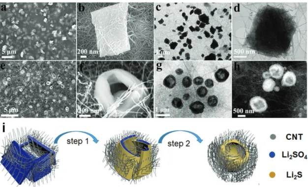
via a facile two-step method (see the Experimental Sec-tion for the detailed fabricaSec-tion process). First, plate-shaped Li2SO4 particles embedded in a CNT network (plate-Li2SO4/
CNT) (Figure 1, left) are obtained by the precipitation of the Li2SO4·H2O aqueous solution in CNT containing ethanol
solution and subsequent filtration. Second, the as-prepared plate-Li2SO4/CNT electrodes are converted to holey-Li2S/CNT
electrodes (Figure 1, middle) via a carbothermal reduction reaction under N2 gas at 700 °C for 3 h. The resulting
holey-Li2S/CNT electrode is freestanding, and thus, can be used as
a cathode without an additional binder. The pristine holey-Li2S particles embedded in the CNT network are oxidized to
higher-order sulfur species, and these are redistributed in the CNT network during the initial charge process (Figure 1, right). More interestingly, with the conversion of these holey-Li2S
par-ticles, micrometer-sized pores can be formed accordingly in the electrodes, which, in the subsequent discharge/charge process, could enhance the lithium ion transport and improve the rate capability.
Figure 2 shows the microstructures and morphologies of the
as-prepared Li2SO4/CNT (Figure 2a–d) and the as-converted
holey-Li2S/CNT electrode (Figure 2e,f). The scanning
elec-tron microscope (SEM) image of the as-prepared Li2SO4/CNT
electrode (Figure 2a) shows that the plate-shaped Li2SO4
pre-cipitates are uniformly distributed in the CNT network. The Li2S plates are quite uniform in size and shape, which is
con-trasted by the pristine Li2SO4·H2O particles (Figure S1,
Sup-porting Information). The X-ray diffraction (XRD) pattern for the as-prepared Li2SO4/CNT electrode (Figure S2, Supporting
Information) indicates that the plate-shaped architectures are a mixture of Li2SO4·H2O (Joint Committee on Powder
Diffrac-tion Standards (JCPDS) card No. 15–0873) and Li2SO4 (JCPDS
card No. 20–0640). A magnified SEM image (Figure 2b) reveals that the plate-Li2SO4 has a rectangular shape with a dimension
of around 1.5 × 1 × 0.3 µm. As shown in Figure 2b, the CNTs and the plate-Li2SO4 are in keen contact, which could facilitate
the carbothermal conversion of the plate-Li2SO4 into Li2S. The
transmission electron microscope (TEM) images (Figure 2c,d) further confirm the structural feature of the Li2SO4 precipitate.
The formation of such a plate structure can possibly profit from the use of negatively charged poly(acrylic) acid (PAA) as a sur-factant, which has a strong affinity with Li ion and thus favors the formation of Li2SO4 plates. The use of neutral poly(vinyl
pyrrolidone) instead of PAA led to the formation of few micrometer-long strip-shaped Li2SO4 (Figure S3, Supporting
Information).[60]
Complete conversion from Li2SO4 to Li2S during the
car-bothermal conversion is confirmed by the XRD pattern of the as-converted Li2S electrode (Figure S4, Supporting
Informa-tion), which shows that the diffraction peaks perfectly match with those of the cubic Li2S
phase (JCPDS card No. 26–1188). Interest-ingly, as shown in the SEM image of the as-converted Li2S electrode (Figure 2e), the
plate-shaped Li2SO4 particle was transformed to
a doughnut-shaped Li2S particle with a hole
(holey-Li2S) during the carbothermal
reduc-tion process. This is different in shape from the shapes of the previously reported Li2S
par-ticles derived from Li2SO4 compounds.[51–59]
A magnified SEM image (Figure 2f) reveals that the holey-Li2S nanoarchitecture has a
wall thickness of 100–150 nm and a hole dia-meter of 200–500 nm. Evolution of the holey
Figure 1. Schematic illustration of the structural changes upon carbothermal conversion from Li2SO4 to Li2S and upon the initial charge process from Li2S to sulfur.
structure was further evidenced by the TEM image (Figure 2g) and scanning transmission electron microscopy (STEM) image (Figure 2f). It should be noted that the holey structure is benefi-cial in improving the lithium ion transfer between the electro-lyte and Li2S particle due to the expanded interface.
The inscrutable structural change from plate to doughnut can be understood as a self-assembly of the plates with the consumption of the near-by CNT matrix (Figure 2i). As indi-cated in the carbothermal reduction reaction equation,[43]
Li2SO4 + 2 C → Li2S + 2 CO2, the CNTs adjacent to the Li2SO4
plates (left) are first consumed and the skin of the Li2SO4 plates
is converted to Li2S, preventing the direct contact between the
surrounding CNTs and inner Li2SO4. However, the reaction
between the generated CO2 and CNT (CO2 + 2 C → 2 CO)
produces CO,[61] and the carbothermal reduction of the inner
Li2SO can occur due to the strong reducing power of CO
(Li2SO4 + 4 CO → Li2S + 4 CO2). The carbothermal
conver-sion accompanies the compaction of the plates, and due to the absence of the nearby CNTs, the resulting Li2S plates become
closer and eventually merge into a holey structure (right). The absence of CNT inside the hole suggests that the removal of CNT drives the assembly of the Li2S plates. The jointing of
two plates observed for the holey-Li2S particle (Figure S5,
Sup-porting Information) further supports the self-assembled pro-cess of Li2S plates.
For comparison, a Li2S particulate without any holes was
prepared by further heating the above holey-Li2S
nanoarchi-tectures at 1000 °C for 3 h. Since the applied temperature is higher than the melting point of Li2S (938 °C), the holey
structure was disrupted and a nonholey Li2S particulate was
obtained, as shown in the SEM image and XRD pattern of
the nonholey Li2S (solid-Li2S) (Figures S6 and S7, Supporting
Information).
To achieve high performance graphite/Li2S batteries, the
selection of liquid electrolytes presents a challenge. In this work, we paid attention to 3 m LiTFSI DOL/DME electrolytes
by considering the balance between high oxidation stability, high ionic conductivity, and the compatibility with Li2S cathode
and graphite anode. As shown in Figure 3a, the 3 m LiTFSI
DOL/DME electrolytes with different DOL/DME volume ratios (DOL/DME = 100/0, 85/15, 75/25, 50/50, and 0/100) showed higher oxidation stabilities compared with 1 m LiTFSI in DOL/
DME = 50/50 with 0.2 m LiNO3, which is conventionally used
for Li2S or sulfur batteries. Although the oxidative stability
might be further improved by increasing the LiTFSI concen-tration, there is a significant loss in ionic conductivity as pre-viously reported.[59] and due to a solubility limit of LiTFSI salt
at room temperature, the concentrations over 3 m could not be
achieved (Figure S8, Supporting Information).
In order to check the compatibility of the 3 m TFSI DOL/
DME electrolytes with graphite anode, the CEs during the 0.1 C rate cycling were measured for the graphite/Li batteries with the 3 m LiTFSI DOL/DME electrolytes. As shown in Figure 3b,
the DOL/DME = 100/0, 85/15, and 0/100 electrolyte have an ini-tial CE of 82.2%, 82.2%, and 82.6%, respectively. These values are much higher than those of the DOL/DME = 75/25 (71.9%) and 50/50 (≈59.7%) and the electrolytes with a concentration of 1 m (16.3%) and 2 m (65.4%) LiTFSI in DOL/DME = 85/15,
respectively (Figure S9, Supporting Information), suggesting a relatively smaller irreversible lithium consumption for SEI for-mation on graphite for the three electrolytes. For the DOL-rich electrolytes (DOL/DME = 100/0, 85/15, and 75/25), the CEs
Figure 2. Structural characterization of Li2SO4/CNT and Li2S/CNT electrodes: a,b) SEM images and c,d) TEM images of the as-prepared Li2SO4/CNT
electrode. e,f) SEM images, g) TEM image, and h) STEM image of the as-prepared Li2S/CNT electrode. i) A suggested mechanism for the formation
www.advancedsciencenews.com www.advancedscience.com
reached over 99% after a few cycles, indicating the formed SEI films are quite stable. For the DOL/DME = 50/50 electrolytes, CEs gradually increased with the cycle, suggesting a gradual coverage of the SEI film on the graphite anode with the cycle. The DOL/DME = 0/100 electrolyte exhibited a fast CE fade with the cycle, which indicates that the SEI layer formed by 3 m TFSI
in DME is not dense enough to prevent the cointercalation of the lithium ion and DME molecular into graphite.[62] The low
irreversible capacity loss for the DOL-rich electrolytes can be associated with the formation of thin and uniform polymeric layer on graphite in DOL-based electrolytes. The advantage of the DOL-rich electrolytes is also supported by the good cycling stabilities for the various electrolytes (Figure 3c). For the DOL-rich electrolytes (DOL/DME = 100/0, 85/15, and 75/25), highly stable cycling performances with discharge capacities higher than 350 mA g−1 were obtained over 40 cycles, which could be ascribed to a compact and uniform SEI layer derived from the DOL solvent[63] and an electrochemically stable SEI layer.[64]
On the other hand, the DOL/DME = 0/100 electrolyte showed a fast capacity fade (Figure 3c, blue) due to the cointercalation. A more stable cycling performance was observed for the DOL/ DME = 50/50 electrolyte, meaning that the introduction of DOL solvent improves the SEI layer. However, the discharge capaci-ties were quite low (≈220 mAh g−1), which can be attributed to
the large irreversible capacity at the first charging step. There-fore, the DOL-rich electrolytes (DOL/DME = 100/0, 85/15, and 75/25) are more suitable for the graphite anode.
The compatibilities with Li2S cathode for the three
DOL-rich electrolytes were assessed with Li/holey-Li2S batteries. As
shown in Figure S10 in the Supporting Information, the first discharge capacity was 773, 880, 792, and 870 mAh g−1 for
DOL/DME = 100/0, 85/15, and 75/25 and 50/50, respectively. The discharge voltage plateau was 2.05, 2.10, 2.10, and 2.10 V for DOL/DME = 100/0, 85/15, 75/25, and 50/50 respectively. However, the initial potential barrier of Li2S cathode increases
with the increase of DME content in the electrolyte and, when the content of DME arrives at 100%, the initial charge process quickly completed with a very low charge/dis-charge capacity (Figure S10e, Supporting Information). These results indicate that a certain amount of DME is needed to attain the compatibility with the Li2S cathode, as previously
observed for Li/sulfur batteries.[65,66] As compared (Table S1,
Supporting Information), the ionic conductivity was the highest for DOL/DME = 85/15 among the three 3 m electrolytes and
the lower concentrated electrolytes. Therefore, taking the above results into consideration, the 3 m LiTFSI DOL/DME = 85/15
electrolyte was selected for the graphite/holey-Li2S battery. Figure 4a compares the initial charge/discharge curves at
the 0.1 C rate for the graphite/holey-Li2S and
graphite/solid-Li2S batteries. The holey-Li2S cathode showed a lower initial
potential barrier than the solid-Li2S electrode, which means
that the holey structure facilitates the lithium extraction from Li2S. The charging capacity for the first charging with a cut-off
voltage of 3.8 V was 1166 mAh g−1 for the graphite/holey-Li2S
and 750 mAh g−1 for the graphite/solid-Li
2S. It clearly shows
that, by introducing the submicrometer scale hole to the Li2S
particle, the charging overpotential for the Li2S oxidation can
be considerably lowered and a higher depth of charging can be obtained.
The cycling performances of the graphite/holey-Li2S battery
and graphite/solid-Li2S battery at 0.2 C after the initial
activa-tion were investigated (Figure 4b). The graphite/holey-Li2S
battery delivered a discharge specific capacity of 712 mAh g−1
at the first cycle and 583 mAh g−1 at 100 cycles, which is the highest value among the graphite/Li2S batteries ever reported
(Table S2, Supporting Information). The graphite/holey-Li2S
battery showed a lower capacity fade rate (0.184%/cycle) than the Li metal/holey-Li2S battery (0.414%/cycle) (Figure S11,
Supporting Information), demonstrating the benefit of using graphite instead of Li metal in terms of cycling stability. The CEs of the graphite/holey-Li2S battery were maintained above
99% during the whole cycles, which is contrasted by the CEs around 98% for the Li /holey-Li2S battery (Figure S8,
Sup-porting Information). It indicates that the polysulfide shuttle can be suppressed in the graphite/holely-Li2S battery. To
fur-ther clarify the polysulfide shuttle issue, the lithium metal and graphite electrode of the Li2S batteries were analyzed by X-ray
photoelectron spectroscopy (XPS) after the initial charge. As shown (Figure S12, Supporting Information), the peaks from the insoluble Li2S/Li2S2 were clearly detected for the lithium
metal surface electrode, while these peaks were unseen for the graphite surface, ensuring the prevention of polysulfide shuttle in the graphite/Li2S battery. The discharge capacity of
the graphite/solid-Li2S battery gradually increased from 237
to 450 mAh g−1 during the first 30 cycles, followed by a mild
capacity fade. The initial capacity increase in the early cycles suggests that the unactivated Li2S particles gradually
decom-posed during the cycle. In spite of the additional Li2S activation, Figure 3. Electrolyte characterizations. a) Oxidation stability of the 3 m LiTFSI-DOL/DME electrolytes with various DOL/DME ratios (100/0, 85/15,
75/25, 50/50, and 0/100 in volume) and conventional electrolytes (1 m LiTFSI in DOL/DME = 50/50 with 0.2 m LiNO3). b) The CEs and c) cycling
the maximum discharge capacity was still far lower than that of the holey-Li2S electrode.
The rate capability of the holey-Li2S electrode was evaluated
by investigating the discharge capacities for five cycles at a dis-charge rate with a successively increasing disdis-charge rate as 0.1, 0.2, 0.3, 0.4 0.5, 0.6, 0.8, and 1 C and returning to 0.1 C. As shown in Figure 4d, the averaged discharge capacity was 760, 749, 734, 717, 700, 677, 632, and 570 mAh g−1 for the discharge rate of 0.1, 0.2, 0.3, 0.4 0.5, 0.6, 0.8, and 1 C, respectively. When the discharge current density returned to 0.1 C, a high discharge capacity of 664 mAh g−1 was recovered. The capacity retention
from the C rate increase from 0.1 to 1 C was 75%. In addition, the graphite/holey-Li2S battery showed a high discharge
poten-tial plateau of 1.99 V at 0.1 C and 1.68 V at 1 C (Figure 4e), indi-cating a high power and energy density for the holey-Li2S/CNT
electrode. The exceptionally excellent rate capacity can be attrib-uted to the multiscale porosity of the activated holey-Li2S
elec-trode. After the initial activation, micrometer-sized pores were generated with the decomposition of the holey-Li2S particles
(Figure S13, Supporting Information), which will be described in a later section. For sulfur cathodes, the efficacy of the mul-tiscale porosity with micrometer and submicrometer pores in enhancing the rate capability was previously demonstrated.[67]
The superiority of the graphite/holey-Li2S battery can be
further supported by a comparison of battery energy densities between the graphite/LiCoO2 and graphite/holey-Li2S batteries
(Figure 4e; Table S3, Supporting Information). The areal capaci-ties of the two cathodes were controlled to be identical for fair comparison. As marked in Figure 4e, the energy density (based on the total mass of cathode and anode) at a current density of 56 mA g−1 (based on whole cathode mass) is 270 Wh kg−1
for the graphite/holey-Li2S battery and 206 Wh kg−1 for the
graphite/LiCoO2 battery, respectively. The comparison indicates
that the holey-Li2S cathodes can exceed conventional metal
oxide cathode in terms of energy density.
Figure 4f shows an extended cycling stability test at 1 C for the graphite/holey-Li2S battery. When the current density
was increased to 1 C after the initial activation at 0.1 C for the cycling, the discharge capacity at the first cycle was as low as 195 mAh g−1. This is because the redistribution of the sulfur species over the CNT network was not fully proceeded during the initial activation. However, the discharge capacity gradu-ally increased up to a maximum value of 400 mAh g−1 after
70 cycles, which was probably due to a gradual redistribution. To our interest, the discharge capacity of 300 mAh g−1 was
maintained at 600 cycles with a high CE of 99%, which firmly demonstrates the merit of the graphite/holey-Li2S battery in
terms of discharge capacity and cycling stability.
According to the initial electrochemical reaction of Li2S
cathode:Li2S → S + 2Li+ + 2e−, the original Li2S is converted
into lithium polysulfides and sulfur upon the initial activation process. Accordingly, the electric energy is stored in the battery
Figure 4. a) The initial charge/discharge curves at 0.1 C and, b) cycling performance at a 0.2 C for the graphite/holey-Li2S and graphite/solid Li2S
bat-teries. c) Rate capability and d) the charge/discharge curves at various C rates for the graphite/holey-Li2S battery. e) Comparison of the energy densities
www.advancedsciencenews.com www.advancedscience.com
system, which can be used in the discharge process. Therefore, the initial activation process is highly critical to the electrochem-ical performances of Li2S batteries. To further understand the
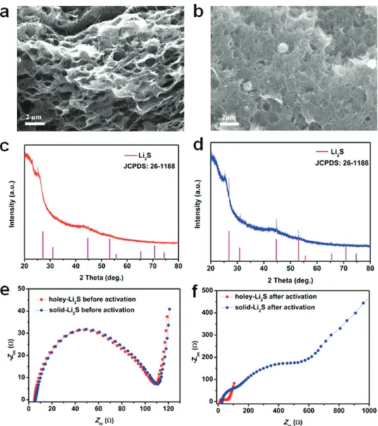
structural and electrochemical changes during the initial activa-tion for the holey-Li2S and solid-Li2S cathodes, SEM, XRD, and
electrochemical impedance spectroscopy (EIS) analysis were conducted for the two electrodes, and the results are compared in Figure 5. After the initial activation, the holey-Li2S particles
completely disappeared (Figure 5a); however, some portion of the solid-Li2S particles remained in the CNT matrix as shown in
the SEM images taken after the initial activation (Figure 5b). The XRD pattern of the holey-Li2S electrode after the initial activation
did not show any peaks from crystalline Li2S (Figure 5c),
indi-cating that the crystalline Li2S is completely decomposed (more
easily decomposed for amorphous Li2S during charging[68])
and the charged sulfur products are in their amorphous state. However, the XRD patterns from Li2S were clearly seen
(Figure 5d) after the initial activation process for the solid-Li2S
electrode, indicating the presence of undecomposed, residual Li2S. As shown in Figure 5e, the impedances of the two
elec-trodes were nearly identical before the initial activation. How-ever, after the initial activation, the impedances of the two batteries became very different (Figure 5f). For the holey-Li2S
cathode, the semicircles were significantly reduced, indicating a faster charge transfer reaction after the activation. In con-trast, for the solid Li2S cathode, two large semicircles and a
long low frequency tail appeared after the activation. The small semicircle for the activated holey-Li2S cathode is in good
agree-ment with the formation of amorphous charged sulfur spe-cies and effective redistribution of these spespe-cies over the CNT matrix with the multiscale porosity. The appearance of the two semicircles may reflect the existence of decomposed and unde-composed regions in the CNT matrix. The EIS results indi-cate that the holey-Li2S structure is quite effective in achieving
a high Li2S utilization and constructing high-performance
LFA/Li2S batteries.
Figure 5. Characterization of the holey-Li2S and solid-Li2S cathodes after initial charge process. a) SEM image and b) XRD pattern for the holey-Li2S
cathode. c) SEM image and d) XRD pattern for the solid-Li2S electrode. Comparison of the Nyquist plots of the AC impedances for the holey-Li2S and
In summary, a novel holey-Li2S nanoarchitecture was
achieved by the newly invented carbothermal conversion pro-cess, which features the formation of plate-shaped Li2SO4
par-ticles and the self-assembly of the plates during the carbon thermal conversion from Li2SO4 to Li2S. In order to reduce the
electrolyte decomposition in the Li2S cathode at high potentials
and the irreversible capacity loss of graphite anode, 3 m LiTFSI
in DOL-rich DOL/DME electrolytes were newly designed. With the combination of the holey-Li2S cathode and the
concen-trated, DOL-rich electrolyte, the resulting graphite/holey-Li2S
battery provided a record high specific capacity of 810 mAh g−1 at 0.1 C and exhibited excellent cycling stability over 600 cycles at 1 C rate. The systematic variations of the Li2S structure,
elec-trolyte composition, and anode material (graphite and Li metal) indicate that the high performances of the graphite/holey-Li2S
battery can be attributed to the three cooperative contributions; 1) The holey-Li2S nanostructure which facilitates the
decompo-sition of Li2S particles during the initial activation, 2) the
forma-tion of a stable SEI layer on graphite with the electrolyte, and 3) the prevention of the polysulfide shuttle due to the use of the graphite anode. We believe that the novel holey-Li2S
nanoarchi-tectures and the electrolyte design can boost the development of high-energy LFA/Li2S batteries for practical applications.
Experimental Section
Fabrication of Electrode Materials: In this work, the commercial
lithium sulfate monohydrate (Li2SO4·H2O, Sigma-Aldrich, >99%), PAA
(Sigma-Aldrich), ethanol (EMD millipore corporation), and poly(vinyl pyrrolidone) (PVP, Mw = 40 000, Sigma-Aldrich) were used without
further purification.
In a typical experiment, the freestanding holey-Li2S/CNT electrodes
were fabricated by the following two steps. First, the sandwich-typed plate-Li2SO4/CNT electrodes were prepared by a precipitation method.
Detailedly, an 80 mg of Li2SO4·H2O powder was dissolved into a
5 mL of deionized water upon stirring to form a transparent Li2SO4
solution. At the same time, a 25 mg of CNT and a 100 mg of PAA were in turn added to a 50 mL of absolute ethanol to form a uniformly dispersed CNT suspension via a sonication of 30 min. Then, another CNT suspension was prepared by the same treatment (Recipe: 10 mg CNT, 20 mg PVP, and 20 mL absolute ethanol). After that, the suspension containing a 25 mg of CNT mixed with a more 50 mL of ethanol (total volume: 100 mL) and the prepared Li2SO4 aqueous
solution were soaked in an iced water bath for 30 min upon stirring. Followed this step, the icy Li2SO4 solution was transferred to a syringe
and was injected slowly to the icy CNT suspension upon stirring to obtain a uniform Li2SO4/CNT suspension. Finally, the Li2SO4/CNT
suspension was used to fabricate a sandwich-typed Li2SO4/CNT film by
a vacuum filtration (The unused CNT suspension was evenly divided into two parts and was filtrated to as a bottom and an upper CNT layer, respectively. The as-prepared Li2SO4/CNT suspension was filtrated
into the two CNT layers). The as-fabricated sandwich-typed film was peeled off and dried, and was punched into disks with a diameter of 12 mm for further drying at room temperature for overnight. Second, the holey-Li2S/CNT electrodes were obtained by a carbothermal
reaction. Operationally, the as-prepared Li2SO4/CNT electrodes were
put into the tube furnace under a flowing N2 at 700 °C for 3 h and
were converted into final holey-Li2S/CNT electrodes. The solid-Li2S/
CNT electrodes were obtained via a further heat treatment of holey-Li2S/CNT at 1000 °C for 3 h. The Li2S content and Li2S area loading
in the two electrodes according to the mass change of before and after dissolution of Li2S into ethanol and deionized water are around
48 wt% and 2.0–2.25 mg cm−2, respectively.
Microstructure Characterization: The crystalline phase structures of all
the converted electrodes were characterized by XRD (Smart lab). The morphology and structure of the electrodes were characterized by SEM (S4800) and TEM (Tecnai F30 ST). XPS characterization was carried out on an X-ray photoelectron spectroscopy (Kα). EIS data were collected in a frequency range of 1 MHz to 10 Hz using an alternating current (AC) impedance analyzer with amplitude of 10 mV. The electrochemical measurements were carried out on a battery cycler (TOSCAT-3000U) at 25 °C.
Electrochemical Characterization: Electrochemical performances of
the electrodes were evaluated by using the assembled button-type batteries. The holey-Li2S/CNT and solid-Li2S/CNT electrodes were used
as a working electrode and lithium metal foil (half batteries) or graphite electrode (full batteries) (provided by Samsumg Company) were used as a counter electrode. Celgard 2400 and 3 m-LiTFSI in DOL/DME (=85/15)
were used as a separator and an electrolyte, respectively. All the batteries were assembled in an argon-filled glove box (H2O and O2 content:
<1 ppm). For charge/discharge behavior at a constant current density, the Li/Li2S batteries were first charge to 4.0 V then discharged to 1.5 V
at a rate of 0.1 C (1 C = 1166 mA g−1). After that, the battery was cycled
at a potential range from 1.5 to 3.0 V at a rate of 0.2 C. For the graphite/ Li2S full batteries (the capacity ratio of graphite anode and Li2S cathode
is around 1.05–1.1:1), the batteries were first charged to 3.8 V and then discharged to 1.0 V at a rate of 0.1 C. Subsequently, the batteries were cycled at a rate of 0.2 C/1 C with a potential range from 1.0 to 3.0 V. The rate capabilities of the graphite/holey-Li2S battery were evaluated in a
successive manner by varying the charge/discharge current density as 0.1, 0.2, 0.3, 0.4 0.5, 0.6, 0.8, and 1 C, and finally went back to 0.1 C, respectively.
Supporting Information
Supporting Information is available from the Wiley Online Library or from the author.
Acknowledgements
Financial support from the KAIST Institute for the NanoCentury, the Korea Institute of Science and Technology (KIST) Institutional Program (Project No. 2E26291), and the National Research Foundation of Korea (Grant No. NRF-2016M1B3A1A01937431).
Conflict of Interest
The authors declare no conflict of interest.
Keywords
concentrated electrolytes, graphite/Li2S batteries, holey structures, Li2S
cathodes, Li2S utilization
Received: January 25, 2018 Revised: April 4, 2018 Published online: May 7, 2018
[1] S.-E. Cheon, K.-S. Ko, J.-H. Cho, S.-W. Kim, E.-Y. Chin, H.-T. Kim,
J. Electrochem. Soc. 2003, 150, A796.
[2] S.-E. Cheon, K.-S. Ko, J.-H. Cho, S.-W. Kim, E.-Y. Chin, H.-T. Kim,
J. Electrochem. Soc. 2003, 150, A800.
[3] S. Xin, L. Gu, N. Zhao, Y. Yin, L. Zhou, Y. Guo, L. Wan, J. Am. Chem.
www.advancedsciencenews.com www.advancedscience.com [4] K. E. Hendrickson, L. Ma, G. Cohn, Y. Lu, L. A. Archer, Adv. Sci.
2015, 2, 1500068.
[5] M. Liu, F. Ye, W. Li, H. Li, Y. Zhang, Nano Res. 2016, 9, 94. [6] S. Zhang, K. Ueno, K. Dokko, M. Watanabe, Adv. Energy Mater.
2015, 5, 1500117.
[7] J. Yan, X. Liu, B. Li, Adv. Sci. 2016, 3, 1600101.
[8] S. Yuan, Z. Guo, L. Wang, S. Hu, Y. Wang, Y. Xia, Adv. Sci. 2015, 2, 150007.
[9] A. Shyamsunder, W. Beichel, P. Klose, Q. Pang, H. Scherer, A. Hoffmann, G. K. Murphy, I. Krossing, L. F. Nazar, Angew. Chem.,
Int. Ed. 2017, 56, 6192.
[10] D. Liu, C. Zhang, G. Zhou, W. Lv, G. Ling, L. Zhi, Yang, Adv. Sci. 2018, 5, 170027.
[11] C. Zu, A. Manthiram, Adv. Energy Mater. 2014, 4, 1400897.
[12] H. Yao, G. Zheng, P. C. Hsu, D. Kong, J. J. Cha, W. Li, Z. W. Seh, M. T. McDowell, K. Yan, Z. Liang, V. K. Narasimhan, Y. Cui, Nat.
Commun. 2014, 5, 3943.
[13] W. Li, Z. Liang, Z. Lu, X. Tao, K. Liu, H. Yao, Y. Cui, Nano Lett. 2015,
15, 7394.
[14] S. Zheng, Y. Chen, Y. Xu, F. Yi, Y. Zhu, Y. Liu, J. Yang, C. Wang, ACS
Nano 2013, 7, 10995.
[15] Z. Li, S. Zhang, S. Terada, X. Ma, K. Ikeda, Y. Kamei, C. Zhang, K. Dokko, M. Watanabe, ACS Appl. Mater. Interfaces 2016, 8, 16053. [16] G. Tan, R. Xu, Z. Xing, Y. Yuan, J. Lu, J. Wen, C. Liu, L. Ma, C. Zhan,
Q. Liu, T. Wu, Z. Jian, R. Shahbazian-Yassar, Y. Ren, D. J. Miller, L. A. Curtiss, X. Ji, K. Amine, Nat. Energy 2017, 2, 17090.
[17] Y. Wu, T. Yokoshima, H. Nara, T. Momma, T. Osaka, J. Power
Sources 2017, 342, 537.
[18] N. Wang, N. Zhao, C. Shia, E. Liu, C. He, F. He, L. Ma, Electrochim.
Acta 2017, 256, 348.
[19] J. Hassoun, B. Scrosati, Angew. Chem., Int. Ed. 2010, 49, 2371. [20] Y. Yang, M. T. McDowell, A. Jackson, J. J. Cha, S. S. Hong, Y. Cui,
Nano Lett. 2010, 10, 1486.
[21] K. Zhang, L. Wang, Z. Hu, F. Cheng, J. Chen, Sci. Rep. 2014, 4, 6467. [22] H. Jha, I. Buchberger, X. Cui, S. Meini, H. A. Gasteiger, J.
Electro-chem. Soc. 2015, 162, A1829.
[23] Z. Li, Y. Kamei, M. Haruta, T. Takenaka, A. Tomita, T. Doi, S. Zhang, K. Dokko, M. Inaba, M. Watanabe, Electrochemistry 2016, 84, 887. [24] J. Balach, T. Jaumann, L. Giebeler, Energy Storage Mater. 2017, 8,
209.
[25] M. Yu, Z. Wang, Y. Wang, Y. Dong, J. Qiu, Adv. Energy Mater. 2017,
7, 1700018.
[26] M. Liu, Y. X. Ren, H. R. Jiang, C. Luo, F. Y. Kang, T. S. Zhao, Nano
Energy 2017, 40, 240.
[27] Y. Yang, G. Zheng, S. Misra, J. Nelson, M. F. Toney, Y. Cui, J. Am.
Chem. Soc. 2012, 134, 15387.
[28] K. Cai, M.-K. Song, E. J. Cairns, Y. Zhang, Nano Lett. 2012, 12, 6474. [29] T. Takeuchi, H. Sakaebe, H. Kageyama, H. Senoh, T. Sakai,
K. Tatsumi, J. Power Sources 2010, 195, 2928.
[30] X. Meng, D. J. Comstock, T. T. Fister, J. W. Elam, ACS Nano 2014,
8, 10963.
[31] C. Wang, X. Wang, Y. Yang, A. Kushima, J. Chen, Y. Huang, J. Li,
Nano Lett. 2015, 15, 1796.
[32] F. Ye, M. Liu, X. Zhang, W. Li, Z. Pan, H. Li, S. Zhang, Y. Zhang,
Small 2016, 12, 4966.
[33] F. Wu, H. Kim, A. Magasinski, J. T. Lee, H.-T. Lin, G. Yushin, Adv.
Energy Mater. 2014, 4, 1400196.
[34] L. Chen, Y. Liu, F. Zhang, C. Liu, L. L. Shaw, ACS Appl. Mater.
Inter-faces 2015, 7, 25748.
[35] C. Nan, Z. Lin, H. Liao, M.-K. Song, Y. Li, E. J. Cairns, J. Am. Chem.
Soc. 2014, 136, 4659.
[36] F. Ye, Y. Hou, M. Liu, W. Li, X. Yang, Y. Qiu, L. Zhou, H. Li, Y. Xu, Y. Zhang, Nanoscale 2015, 7, 9472.
[37] L. Chen, Y. Liu, M. Ashuri, C. Liu, L. L. Shaw, J. Mater. Chem. A 2014, 2, 18026.
[38] G. Zhou, E. Paek, G. S. Hwang, A. Manthiram, Adv. Energy Mater. 2016, 6, 1501355.
[39] Z. W. Seh, H. Wang, P.-C. Hsu, Q. Zhang, W. Li, G. Zheng, H. Yao, Y. Cui, Energy Environ. Sci. 2014, 7, 672.
[40] Z. W. Seh, J. H. Yu, W. Li, P.-C. Hsu, H. Wang, Y. Sun, H. Yao, Q. Zhang, Y. Cui, Nat. Commun. 2014, 5, 5017.
[41] Z. Yang, J. Guo, S. K. Das, Y. Yu, Z. Zhou, H. D. Abruna, L. A. Archer,
J. Mater. Chem. A 2013, 1, 1433.
[42] J. Liu, H. Nara, T. Yokoshima, T. Momma, T. Osaka, Electrochim.
Acta 2015, 183, 70.
[43] M. Kohl, J. Bruckner, I. Bauer, H. Althues, S. J. Kaskel, J. Mater.
Chem. A 2015, 3, 16307.
[44] D. H. Wang, X. H. Xia, D. Xie, X. Q. Niu, X. Ge, C. D. Gu, X. L. Wang, J. P. Tu, J. Power Sources 2015, 299, 293.
[45] Z. Li, S. Zhang, C. Zhang, K. Ueno, T. Yasuda, R. Tatara, K. Dokko, M. Watanabe, Nanoscale 2015, 7, 14385.
[46] D. H. Wang, D. Xie, T. Yang, Y. Zhong, X. L. Wang, X. H. Xia, C. D. Gu, J. P. Tu, J. Power Sources 2016, 331, 475.
[47] J. Zhang, Y. Shi, Y. Ding, L. Peng, W. Zhang, G. Yu, Adv. Energy
Mater. 2017, 7, 1602876.
[48] Y. Chen, S. Lu, J. Zhou, W. Qin, X. Wu, Adv. Funct. Mater. 2017, 27, 1700987.
[49] S. Zhang, M. Liu, F. Ma, F. Ye, H. Li, X. Zhang, Y. Hou, Y. Qiu, W. Li, J. Wang, J. Wang, Y. Zhang, J. Mater. Chem. A 2015, 3, 18913. [50] K. R. Ryan, L. Trahey, B. J. Ingram, A. K. Burrell, J. Phys. Chem. C
2012, 116, 19724.
[51] P. Zeng, Y. Han, X. Duan, G. Jia, L. Huang, Y. Chen, Mater. Res. Bull. 2017, 95, 61.
[52] Y. Z. Zhang, S. Liu, G. C. Li, G. R. Li, X. P. Gao, J. Mater. Chem. A 2014, 2, 4652.
[53] E. S. Shin, K. Kim, S. H. Ohand, W. I. Cho, Chem. Commun. 2013,
49, 2004.
[54] L. M. Suo, Y. S. Hu, H. Li, M. Armand, L. Q. Chen, Nat. Commun. 2013, 4, 1481.
[55] J. T. Lee, Y. Zhao, S. Thieme, H. Kim, M. Oschatz, L. Borchardt, A. Magasinski, W. I. Cho, S. Kaskel, G. Yushin, Adv. Mater. 2013, 25, 4573.
[56] Y. Yamada, M. Yaegashi, T. Abe, A. Yamada, Chem. Commun. 2013,
49, 11194.
[57] A. Bhargav, M. Wu, Y. Fu, J. Electrochem. Soc. 2016, 163, A1543. [58] D. Lv, P. Yan, Y. Shao, Q. Li, S. Ferrara, H. Pan, G. L. Graff, B. Polzin,
C. Wang, J. Zhang, J. Liu, J. Xiao, Chem. Commun. 2015, 51, 13454.
[59] F. Wu, A. Magasinski, G. Yushin, J. Mater. Chem. A 2014, 2, 6064. [60] F. Ye, H. Noh, J. Lee, H. Lee, H. Kim, J. Mater. Chem. A 2018, 6
6617.
[61] L. Qie, A. Manthiram, Adv. Mater. 2015, 27, 1694.
[62] T. Abe, N. Kawabata, Y. Mizutani, M. Inaba, Z. Ogumi, J.
Electro-chem. Soc. 2003, 150, A257.
[63] V. Etacheri, U. Geiger, Y. Gofer, G. A. Roberts, I. C. Stefan, R. Fasching, D. Aurbach, Langmuir 2012, 28, 6175.
[64] D. Lu, J. Tao, P. Yan, W. A. Henderson, Q. Li, Y. Shao, M. L. Helm, O. Borodin, G. L. Graff, B. Polzin, C. M. Wang, M. Engelhard, J. Zhang, J. J. De Yoreo, J. Liu, J. Xiao, Nano Lett. 2017, 17, 1602. [65] R. Miao, J. Yang, X. Feng, H. Jia, J. Wang, Y. Nuli, J. Power Sources
2014, 271, 291.
[66] A. Bhargav, M. Wu, Y. Fu, J. Electrochem. Soc. 2016, 163, A1543. [67] C.-J. Bae, C. K. Erdonmez, J. W. Halloran, Y.-M. Chiang, Adv. Mater.
2013, 25, 1254.
[68] X. Meng, D. J. Comstock, T. T. Fister, J. W. Elam, ACS Nano 2014,