ICCAS2005 June 2-5, KINTEX, Gyeonggi-Do, Korea
1. INTRODUCTION
Load Test Simulator Development for Steam Turbine-Generator System of
Nuclear Power Plant
Chang-ki Jeong, Jong-an Kim, Byung-chul Kim, In-kyu Choi and Joo-hee Woo
Korea Electric Power Research Institute, Daejeon, Korea(Tel : +82-42-865-5380; E-mail: [email protected] )
Abstract: This paper focuses on development of load test simulator of a steam turbine-generator in a nuclear power plant. When load is taken off from electrical power network, it is very difficult to effectively control the steam flow to turbine of the nuclear turbine-generator, because of disturbances, such as electrical load and network unbalance on electrical network. Up to the present time, the conventional control system has been used for the load control on nuclear steam generator, owing to the easy control algorithms and the advantage which have been proven on the nuclear power plant. However, since there are problems with stability control during low power and start-up, only a highly experienced operator can operate during those procedures. Also, a great deal of time and an expensive simulator is needed for the training of an operator. The KEPRI is developed simulator for 600MW nuclear power plant to take a test of generator load rejection, throttle valve, and turbine load control. Total load test is implemented before start up.
Keywords: Nuclear power plant, Digital control, Turbine control, Simulator; Load rejection
2. OVERVIEW OF CONTROL SYSTEM OF
NUCLEAR POWER PLANT FOR SIMULATOR
DEVELOPMENT
The steam turbine-generator system is one of the mostimportant components of a nuclear power plant. It is furnished by main feed water from feed water pump and heat from nuclear reactor, to produce electricity. The proper speed and load of nuclear turbine-generator must be maintained, to ensure generating system safety. The factors which affect the flow of the steam generator include feedwater flowrate and temperature, coolant temperature, and main steam flowrate. Since the main steam flowrate depends on the electrical load of the generator, the flow to turbine should be regulated to maintain the proper speed whenever there is a load change. The controller of the nuclear turbine-generator has feedwater flowrate and temperature, coolant flowrate and temperature, main steam flowrate, and electrical load as input. It has the speed control signal of the steam generator as output. So, it is important for the operator to maintain its speed for steady state operation [1], [5].
2.1 Overview of Simulator
The nuclear power plant is compose of facility including high pressure turbine 2, low pressure turbine 4, humidity separator 2, reheater 2, high pressure valve 4, low pressure valve 4, high control valve 4, low pressure shut off valve 4. 2.2 Structure of Simulator
Simulator is to prove reliability and adaptability to field of Software developed by the KEPRI for digital control. Therefore, it should include the characteristics of thermal dynamic of nuclear turbine system.
To prove controllability and the healthy condition of the controller during operation, simulator can simulate transient status, test signal of digital control system derived control system. We set setpoint and simulate operator’s condition for pressure and temperature of steam generator, pressure and temperature of high and low steam, condensation and temperature of condenser through simulator, etc.
In overseas, digital control system or simulator for turbine-generator system of nuclear power plant has been development in the earlier of 1990. Since the control system in nuclear power plant should provide safety and reliability the highly technology need to educate for operator. Especially, the control algorithms of the turbine controller still use PI (Proportional and Integral) because of a safe and the requirement of the proven technology required in only nuclear power plant. Therefore, concern to safety by manual operation during the start-up and low power has been increased. Moreover, for a highly experienced operator, it takes a long time and an expensive facility should be prepared [2].
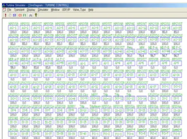
2.3 MMIS for Monitoring and Control
MMIS (Man Machine Interface System) is to play a role display parameter such as pressure and temperature of main steam, pressure of high and low steam, condensation condition and temperature of condenser, opening of high and low valve, process parameter during operating. It has freeze, resume, step, reset function.
The applied control system of a nuclear turbine generator control system must have a very simple and proven algorithm. So, it is very difficult to have both the disturbance-rejecting function and load-following function operating simultaneously, when load change or load takes off. If there is an irregular noise or disturbance, or the operator changes the setpoint to increase load-following function, controlling becomes more difficult.
2.4 Flow diagram of turbine steam
To simulate, it is very important to display turbine and process diagram likely to operating condition including operating parameter.
Fig. 1 shows schematic diagram of turbine and generator system. We should run turbine system to rate speed through High Pressure Stop Valve (HPSV) and High Pressure Governor Valve ((HPGV). After this procedure, steam flow rate to turbine is regulated and output is controlled by high pressure control valve. Of course, all procedure should be displayed on the MMIS
In this paper, load test simulator for the turbine generator control system of the nuclear power plant is developed by the KEPRI. The results obtained through operation and simulation such as, load test, emergency test for over speed, load following capability is described [7].
ICCAS2005 June 2-5, KINTEX, Gyeonggi-Do, Korea
Fig. 3 Turbine model. Fig. 1. Steam flow diagram in simulator.
Since mechanical energy of turbine is given by steam volume, pressure, etc., when enthalpy at input point hi, enthalpy at output point ho is defined, Turbine energy is obtained by
2.5 Relation between and input and output
Fig. 2 shows 2 relation ship between and input and output using variables, signal, signal range to protect power plant and it is coded by C++.
(
i o)
th F h h
P = − (2) 2.8 Generator Model
Model of generator is designed by turbine model based on steam condition.
2.9 Control program
Simulator is structured from model by digital control system based on H/W of Woodward Com., which has Triple Modular Redundancy (TMR)).
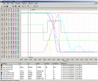
2.10 Load Shut off Test
Load shut off test is performed at rate condition, and turbine and generator speed of 110% on circuit as the Fig. 5.
Fig. 2 Arrangement between input and output in simulator.
2.6 Thermal Dynamic Model
Procedure transferring steam energy to mechanical energy is programmed by thermal equation based on thermal dynamic characteristics with FORTRAN. Valve opening at rate pressure decides flow rate and produce turbine energy using real operating data. Also, the volume of reheater and inertia of turbine and register function to steam flow is regulated through simulation.
2.7 Turbine model
Turbine is composed of high pressure, medium pressure, and low pressure and turbine has the multistep to extract steam. Relationship between pressure drop and flow is drived by Stodolla equation. i i i K F
ρ
ρ
ρ
ρ
2− 02 = (1) where, F, K, ρi, pi, po are mass flow, admittance, density at input point and output point, respectively.Fig. 4. Generator model.
ICCAS2005 June 2-5, KINTEX, Gyeonggi-Do, Korea An additional problem is that it is very difficult to effectively control procedures of the turbine-generator system, because of the difficulty control methods created by disturbances such as load variation, turbine speed, and generator condition. OIS CONTROL SYSTEM SIMULATOR FIELD LVDT LVDT CONTROL SIGNAL STARTUP SPEED, LOAD CONTROL MCB
So, a question of safety has been raised in regards to a manual operation during start-up and low power only a highly experienced operator can operate manually during these stages. In the long run, a great deal of time and an expensive training simulator is needed for the training of the operator.
SPEED PR.
TEMP. In this paper, we describe characteristics of simulator for
test and operating of digital control system of turbine-generator in nuclear power plant developed by the KEPRI.
The developed simulator for digital control system can provide test procedure and operating procedure for safety and reliability. In simulator highest speed is 1954rpm and shut off function of over-speed is 1980rpm. We are expecting it can also improve control reliability and safety through this simulator.
Fig. 5. Structure for load shut off test.
In this paper, the following procedure is introduced for test; [Step 1] Connect the Fig. 6
[Step 2] Install recorder for output of generator, turbine
REFERENCES
speed, valve opening.[Step 3] Perform the parallel operation to network and [1] Manual for Kori nuclear power plant. sustain 600MW at control console. [2] “Micronet Digital Control", Woodward Co. [Step 4] Open circuit breaker of electrical generator and [3] "iFix User's Manual", Intellution ,1996.
observe control variable from recorder. [4] Chang Ki Jung, “Development of nuclear power plant KEPCO Report.
[Step 5] Produce highest speed and variation.
[Step 6] Calculate closed time and floating time when load [5] Zhichao Guo & etc., Nuclear power plant performance study by using neural network, IEEE Trans. on nuclear, science 39( 4)(1992) 915-918.
shut off.
- Turbine speed variation : 1954rpm within 262msec [6] John G.Williams, Intelligent control in safety systems,
IEEE Trans. on nuclear science, 40(6)(1993) 2040-2044.
- HPSV1 floating time: about 70msec
(closing time : 240msec) [7] A.Hoeld, A theoretical model for the calculation of large transients in nuclear natural circulation U-tube steam generators, Nuclear engineering and design 47(1978) 1-23, 1978.
- HPGV1 floating time: 60msec (closing time: 200msec) - LP1GV1 floating time: 140msec (closing time: 360msec)
Fig. 6. Simulation for load shut off.
3. CONCLUSIONS
Since reliability and safety, only the proven advantages of the technology need to use for nuclear power plants. However, if the conventional control system is used in this system, there might be problems with control stability during the low power and start-up procedures.