P2-70 / Y.-S. Kim
IMID 2009 DIGEST •
Abstract
Effect of contamination of liquid crystal on the electrical behavior of liquid crystal display (LCD) by spilled components from color filter layer was investigated. It is noted that the level of contamination was different following the kind of liquid crystal and organic layers. Transmittance curve of LCD cell was shifted by spilled components of color filter and BM materials. C-V curve also showed different behavior following color filter type. The results obtained show the image sticking of LCD can be varied by pairing liquid crystal with color filter materials.
1. Introduction
For liquid crystal display, a residual image of the previous frame is usually called as image sticking [1-3], which is a severe problem regarding the image quality in high information content active matrix displays [4,5]. It is commonly understood that residual DC (R-DC) has some relation with image sticking. However, image sticking effect can originate from the emission of impurities from cell layers into liquid crystal. Three constituents should be taken into consideration: (1) electrolyte ions dissolved in the liquid crystal solvent; (2) polymer layer such as color filter and black matrix; and (3) the metal electrode (usually an ITO film). Since the cell layers such as color filter or black matrix always includes organic/ionic impurities, their emission may lead to a partial compensation of the applied electric field in the liquid crystal bulk.
For TN mode, although ITO layer is dense enough to blocking impurities from organic color filter layer into liquid crystal, common electrode which is made of ITO thin film panel can easily be cracked by external force due to its inorganic nature. It is more severe for overcoat-less IPS mode.
The objective of this work is to compare the effect
of contamination of liquid crystal caused by organic cell layers on the electrical behavior of liquid crystal display (LCD), especially when we consider overcoat-less IPS structure and color filter on TFT (COT or COA).
2. Experimental
Conventional resin of color filters (JSR Co.) and organic black matrix were prepared as impurity sources. Liquid crystal used for conventional twisted nematic (TN_LC) mode and in-plane switching (IPS-LC) mode were prepared respectively.
Organic resin was coated on a bare glass and heat treated with manufacturing process conditions (thickness: 2.0µm, exposure: 300mJ for 15s, baking temperature: 220oC, 30min). Because the cell gap of LCD panel is smaller than 5µm, it is almost impossible to gather liquid crystal from panel or test cell. Therefore, coated substrates were dipped into liquid crystal bulk and stored for 24hrs at 80oC. The exposed area of organic layer was set to 500mm2/g of liquid crystal, which is 40 times smaller than actual panel and similar to the area of column spacer. Contaminated liquid crystals were analyzed by LC-MS (Finnigan DECA XP PLUS).
The test cells which are made of glass substrates (10x10mm, cell gap: 5µm) with alignment layer (SE7492, Nissan Co.) were prepared for the measurement of electric behavior. Alignment layer was formed on non-patterned ITO layer with manufacturing process conditions. After contaminated liquid crystal is injected into the cell, they are thermally treated for 30s at 80oC. The test cells are measured by DMS (DMS 703) and HP4284A LCR meter with probe-station for transmittance-voltage (T-V) curve and capacitance-voltage (C-(T-V) curve, respectively.
Effect of Contamination of Liquid Crystal by Spilled
Components from Color Filter
*Young-Seok Kim and Jeong-No Lee
Display Components & Materials Research Center, Korea Electronics Technology Institute, 68 Yatap-dong, Bundang-du, Seongnam-si, Gyeonggi-do 463-816, Korea
Tel.: 82-31-789-7234, E-mail: [email protected]
P2-70 / Y.-S. Kim
• IMID 2009 DIGEST
3. Results and discussion
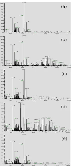
We initially focused on the organic impurities of contaminated liquid crystal by color filter layer. Figure 1 shows the results of LC-MS analysis of IPS type liquid crystal.
2 0 0 4 0 0 6 0 0 8 0 0 1 0 0 0 1 2 0 0 0 1 0 2 0 3 0 4 0 5 0 6 0 7 0 8 0 9 0 1 0 0 4 2 8 . 2 4 1 1 . 2 2 3 1 . 4 4 7 1 . 8 2 6 5 . 4 2 7 9 . 4 1 2 1 . 3 4 8 5 . 7 5 1 5 . 5 6 1 3 . 3 7 4 8 . 0 8 5 0 . 5 1 0 3 3 . 2 1 2 0 2 . 9 [ ] 2 0 0 4 0 0 6 0 0 8 0 0 1 0 0 0 1 2 0 0 0 1 0 2 0 3 0 4 0 5 0 6 0 7 0 8 0 9 0 1 0 0 4 2 8 . 3 4 1 1 . 5 2 3 1 . 3 2 6 5 . 5 8 3 1 . 6 4 4 2 . 3 7 8 7 . 5 8 7 5 . 6 2 9 4 . 3 6 9 9 . 8 9 1 9 . 4 1 2 1 . 3 9 6 3 . 4 6 1 1 . 5 1 0 0 7 . 3 4 7 3 . 6 2 1 8 . 3 1 1 1 1 . 4 1 1 [ ] 2 0 0 4 0 0 6 0 0 8 0 0 1 0 0 0 1 2 0 0 0 1 0 2 0 3 0 4 0 5 0 6 0 7 0 8 0 9 0 1 0 0 4 2 8 . 1 2 3 1 . 4 4 1 1 . 3 2 6 5 . 5 4 7 1 . 9 3 2 9 . 4 1 0 0 . 3 6 1 5 . 1 1 9 9 . 4 7 2 9 . 2 8 4 3 . 2 5 1 5 . 7 9 5 8 . 4 1 0 7 1 . 2 1 2 0 1 . [ ] 2 0 0 4 0 0 6 0 0 8 0 0 1 0 0 0 1 2 0 0 0 1 0 2 0 3 0 4 0 5 0 6 0 7 0 8 0 9 0 1 0 0 3 6 5 . 6 4 1 1 . 5 2 3 1 . 5 7 8 7 . 5 8 3 1 . 4 2 6 5 . 6 4 7 2 . 4 7 4 3 . 6 6 9 9 . 5 8 7 5 . 4 6 5 5 . 5 4 7 3 . 3 9 1 9 . 4 1 0 0 . 4 9 6 3 . 4 1 2 1 . 4 9 7 9 . 4 5 2 3 . 5 1 0 6 7 . 4 2 2 9 . 5 1 1 1 1 . 1 1 1 9 [ ] 2 0 0 4 0 0 6 0 0 8 0 0 1 0 0 0 1 2 0 0 0 1 0 2 0 3 0 4 0 5 0 6 0 7 0 8 0 9 0 1 0 0 4 2 8 . 0 2 3 1 . 4 4 1 1 . 2 2 6 5 . 4 4 7 1 . 8 2 7 9 . 4 1 2 1 . 3 4 8 5 . 7 1 9 9 . 3 4 9 5 . 9 6 1 2 . 3 7 0 9 . 0 8 5 1 . 4 9 8 1 . 8 1 0 6 8 . 9 1 2 8 0
Fig. 1. Organic impurities of contaminated IPS_LC; (a) reference condition (without no organic layer), (b) red color filter, (c) green color filter, (d) blue color filter, (e) carbon black type black resin.
Liquid crystal which contacted with organic layer except BM1 (carbon black type) showed the peaks of organic compounds. In the case of green color filter, relatively small peaks appeared. Because the color of
contaminated liquid crystal was also turned into red and blue, we simply come to a conclusion that not only organic additives which are related mill base but also mill base (colorant) itself is spilled out during contact of organic layer.
Fig. 2. T-V curves of the test cell which is injected (a) IPS_LC and (b) TN_LC.
The spilled components from color filter layer directly deteriorate electrical characteristics of liquid crystal panel. As shown Figure 2(a), the influence of organic impurities on T-V curves of the test cell which is injected IPS_LC was negligible. However, the transmittance was more sensitively varied for TN_LC, especially when the liquid crystal was exposed to the red and blue color filter layer (V= 1.36V, ∆T = 20%) and RGB type black matrix (BM2).
P2-70 / Y.-S. Kim
IMID 2009 DIGEST •
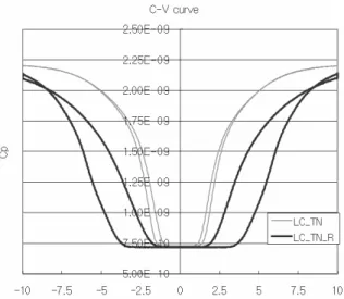
Fig. 3. C-V curves of the test cell which is injected TN_LC and TN_LC_R (Red color filter contacted).
In a real LCD, the residual DC voltage generates during application of AC voltage including DC offset [6]. Therefore, it is important to compare R-DC during application of the external DC voltage with AC voltage. AC voltage was fixed at 60 Hz and 10.0 volt. According to Figure 3, C-V curve of the test cell was shifted and hysteresis was remarkably occurred. This indicates that R-DC strongly depends on the impurities of liquid crystal. Residual DC for various LCs were measured and listed in Table 1.
TABLE 1. Residual DC of test cell by varied capacitance of contaminated liquid crystal (measured by C-V curve). (R-DC) LC-IPS LC-TN Bare glass Red Green Blue BM1 BM2 0.08 0.28 0.13 0.63 0.10 0.43 0.28 1.87 0.13 0.53 0.08 0.63
4. Summary
The mechanism of image-sticking generation has been studied for a long time, but it is not yet sufficiently understood in literature and is presuming that various kinds of factors have entangled. In General, adsorption and desorption of ion impurities of LCs to alignment film is considered as main
mechanism. It is still not clear which component of color filter layer influences dominantly on the R-DC.
However, as shown in this research, the electrical behavior of liquid crystal panel is also affected by organic impurities spilled from color filter layer. Therefore, when we apply overcoat-less IPS and (COT color filter on TFT) structure, these results should be taken into consideration.
5. References
1. A. Lien, C.-J. Chen, H. Inoue and Y. Saitoh, SID Int, Symp, Digest Tech. Papers 203 (1997).
2. I. Gerus, A. Glushchenko, Yu. Kurioz, Yu. Reznikov and O. Tereshchenko, Opto-Electron. Rev.
12, 281 (2004).
3. A.M. Gabovich, P.P. Korniichuk, Yu.A. Reznikov, A.I. Voitenko and S.B. Kwon, SID Int, Symp, Digest Tech. Papers 670 (2006).
4. Y. Nakajono et al, SID Int, Symp, Digest Tech. Papers 219 (1999).
5. J.H. Lee, J. Yi, H.K. Jung, S.G. Lee, H.H. Nam, Y.J. Nam and S.W. Choi, IMID Int, Symp, Digest Tech. Papers 513 (2007).
6. M. Mizukaki, T. Miyashita and T. Uchida, SID Int, Symp, Digest Tech. Papers 673 (2006).