http://dx.doi.org/10.7236/IJASC.2021.10.1.159
Modelling of Optimum Design of High Vacuum System
for Plasma Process
Hyung-Taek Kim
Professor, Department of Advanced Materials Engineering, College of Engineering
Incheon National University, Incheon, Korea
[email protected]
Abstract
Electronic devices used in the mobile environments fabricated under the plasma conditions in high vacuum system. Especially for the development of advanced electronic devices, high quality plasma as the process conditions are required. For this purpose, the variable conductance throttle valves for controllable plasma employed to the high vacuum system. In this study, we analyzed the effects of throttle valve applications on vacuum characteristics simulated to obtain the optimum design modelling for plasma conditions of high vacuum system. We used commercial simulator of vacuum system, VacSim(multi) on this study. Reliability of
simulator verified by simulation of the commercially available models of high vacuum system. Simulated vacuum characteristics of the proposed modelling agreed with the observed experimental behaviour of real systems. Pressure limit valve and normally on-off control valve schematized as the modelling of throttle valve for the constant process-pressure of below 10 . Simulation results plotted as pump down curve of chamber, variable valve conductance and conductance logic of throttle valve. Simulated behaviors showed the applications of throttle valve sustained the process-pressure constantly, stably, and reliably in plasma process.
Keywords: Simulation Modelling, Optimum Design, Plasma Process, Vacuum Characteristics
1. Introduction
Recently, the applications of plasma are indispensable for the cutting-edge technologies such as mobile engineering. Developments of mobile products accomplished with the generation of high quality plasma environments. Highly advanced techniques on the generation, measurements, maintenance of plasma vacuum and evaluation of vacuum system had become an essential for the fabrications of micro electronic devices. Especially, most of the plasma equipment of Integrated Circuit (IC) process which brought the mobile environments are the vacuum systems [1,2]. Applications of high performance of vacuum system expected to be keep growing on next decades. Generally, the manufacturing costs of plasma system are very high and performance characteristics strongly dependent upon the design modelling of system. Therefore, simulation of vacuum systems based on the design factors is very important to predict the vacuum characteristics and reduce the manufacturing expenses considerably for the optimum system design. Among the plasma characteristics of vacuum equipment, the reliable sustainability of constant process-pressure required for the successful process managements. To achieve the reliable constant process-pressure in plasma, it is essential to utilize the variable conductance throttle valve on vacuum system. Applications of variable conductance throttle valve in
IJASC 21-1-17
Manuscript Received: February. 17, 2021 / Revised: February. 22, 2021 / Accepted: February. 24, 2021 Corresponding Author: [email protected]
Tel: +82-32-835-8274, Fax: +82-32-835-0778
160 International Journal of Advanced Smart Convergence Vol.10 No.1 159-165 (2021) plasma system has continued to grow with the advance of electronic devices. Even greater demand and more stringent pressure controls are expected to be imposed on throttle valve demands [3-5]. In this study, we investigated the effects of throttle valve applications on vacuum characteristics for plasma process. Simulation results of the modelled throttle valves suggested the optimum design factors for variable conductance system. Commercial simulator of vacuum system, VacSim(multi), used on this work [6-8] Simulated vacuum
characteristics of the proposed high vacuum modelling were agreed with that of the experimentally observed behavior of real systems. Pressure limit and normally on-off valves schematized as the variable conductance throttle valve for constant process-pressure of below 10 [9,10]. Simulated vacuum characteristics achieved as pump down curve of chamber, variable valve conductance and conductance logic of throttle valve. Simulation results showed the applications of throttle valve sustained the process-pressure constantly, stably, and reliably for high quality plasma.
2. Simulations
2.1. Simulation of plasma system
For the verification of VacSim(multi)simulator’s feasibility, Diffusion pump of plasma was modelled in this
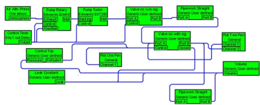
study. Simulation results showed the possibilities of applications and provided useful outcomes for plasma system design in practice. The most commonly used vacuum systems in plasma processing selected as the modelling systems. Modelling based on the commercial specifications of vacuum systems used in experimental applications. Two different modelling with and without trap effects on backstream employed in this modelling with fixed design factors for the chamber, exhaust pipework. Simulation design factors of modelled High Vacuum (HV) systems fixed, with the same parameters used except for the baffling applications in each simulation. Commercially available Diffusion-Mechanical Pump (DP-MP) system employed in this modelling. The proposed HV plasma systems have a straight pipework with a length of 0.3 and a diameter of 0.0254 . Valves employed had internal aperture areas of 5 × 10 and 5 × 10 for rough and high vacuum pumping, respectively, and were normally opened in the absence of a signal. Chamber volume fixed at0.3 and the commercial specifications of the employed mechanical pump models summarized in Table 1. Pump models selected after repetitive simulations to obtain the optimum system modelling. Simulation schematic of modelled diffusion systems with and without baffles illustrated in Figure 1.
Table 1. Commercial specifications of modelled rotary pump of plasma system (Edwards Ltd.)
model name E1M8
pumping speed
(pneurop 6602, 50 ) 255 ∕ ℎ
number of stages 2
ultimate vacuum without gas ballast 7.7 × 10
weight 225
Figure 1. Simulation schematic of plasma system with baffle(bottom) and without baffle(top)
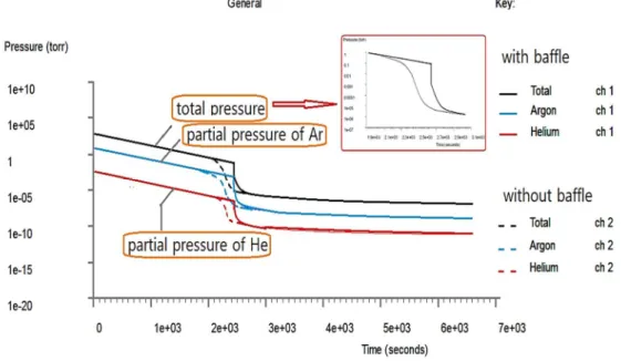
Both models with and without baffle were simulated to compare the effects of baffle applications on plasma characteristics of system. Achieved in situ vacuum characteristics plotted in the form of the pump-down and backstream curves in Figure 2, 3. Dynamic characteristic curves with and without the baffle effects indicated by the dotted and solid lines, respectively. Results showed that the baffle effects are significant to the overall performance of system. Ultimate pressure of the DP system with baffle was reached almost at 10 (Figure 2) which was approximately close as the without baffle model. Effects of baffle employment not observed within the initial evacuation time of 32 minutes. In addition, the pumping down curve with baffle system gradually stabilized compared to the abrupt behavior of without baffle. Application of baffle had a greater effect on the evacuation time and on the degree of backstream than on the ultimate pressure. The initial baffle effects of both DP systems reflected in their pumping times to the ultimate pressure of about 43 minutes without a baffle and 26 minutes with a baffle. Regarding the process time, the decrease of almost half order obtained by the employment of baffle. Figure 3 represented the expected differences on backstream behavior in plasma. Achieved simulation results of baffle effects on vacuum characteristics suggested the feasibility of VacSim(multi) applications for this study. In-situ simulation data plotted as vacuum characteristic curves in
Figure 2, 3 summarized on Table 2.
162 International Journal of Advanced Smart Convergence Vol.10 No.1 159-165 (2021)
Figure 3. Comparison of backstream with and without baffle in plasma Table 2. In-situ simulation data on characteristic curves of modelled system
Modelling of DP system Ultimate pressure ( ) Pumping time ( ) Maximum backstream ( ∕ ) Without Baffle 6 × 10 3003 5.29 × 10 With Baffle 2 × 10 2695 8.03 × 10
2.2. Simulation of throttle valve effects on plasma
VacSim(multi)provide the two different modelling components, pressure limit valve and controlled valve, for
the simulation of variance conductance throttle valve system. The valve components modelled as circular apertures with the size of which reduced to zero when closed. Turbomolecular system commonly utilized in plasma processing employed for this simulation. Commercially available model of Turbomolecular Pump (TMP) chosen as the simulation model. Modelling of the throttle valve by controlled valves was consisted of the control trip and normally open/close valve with signals modules. Control trip component behave like pressure-sensor send control signal “1” if the chamber pressure is lower than the preset pressure. Control signal “1” is fed to the normally open valve which is open when the controlled signal is less than 0.5. Purpose of throttle valve is to sustain the chamber pressure constantly, reliably in plasma. Preset pressure was set to 10 as the constant process-pressure. Therefore, the modelling of controlled valve provided variable conductance characteristics by closing the normally open valve unless the chamber pressure is higher than 10 . To sustain the variable conductance accurately, the controlled valves are fully open and close according to the plasma pressure of chamber. If the chamber pressure fall down to below 10 , control valve closed to keep chamber pressure constant. The closed indicator is 1 when the valve is closed. Simulation scheme of the controlled valve represented in Figure 4.
Figure 4. Simulation schematic of throttle valve system for controlled plasma
Pressure limit valve opened whenever the preset pressure difference between the high and low-pressure port is greater than the constant plasma-pressure of 10 . The amount the valve open is proportional to the sensing pressure difference during simulation. High and low-pressure of pressure limit component represented the in-situ pressures at chamber and at exhaust pipe toward TMP respectively. The pressure limit valve does not have a control input, but have analogue signaling output (0=closed, 1=open). Figure 5 showed the simulation scheme of variable conductance system by pressure limit valve. Reflect the temperature increase during plasma deposition process, outgassing effect at fixed process temperature of 170 also considered on modelling.
Figure 5. Simulation schematic of pressure-limit valve system without outgassing
3. Results
Feasibility of employed simulator, VacSim(multi), was verified with the simulation of commercial model of
high vacuum system. Simulation of controlled valve system showed that the elapsed time of 1147 ( ) to be reached the valve closed agreed with the pumping down characteristics of chamber (Figure 6). After the elapsed time of 1147 ( ), constant chamber pressure of approximately 10 sustained as the dotted line on pump-down curve. As the solid line on the curve, the pressure at port A of normally open control valve indicate the point near to TMP was reached to ultimate pressure of 10 . Characteristics in variable conductance for the constant plasma pressure obtained by simulation of controlled valve modelling. As shown on Figure 6, there was no partial open-close state on the operation of control valve. During the valve duration, approximately 1653 ( ), of constant chamber pressure, the virtual leakage was estimated to be negligible. Suggested modelling of controlled valve showed the possibility of simulation for variable conductance system. In addition, the achieved simulation results were consistent with the observed pumping behavior of throttle valve experimentally.
164 International Journal of Advanced Smart Convergence Vol.10 No.1 159-165 (2021)
Figure 6. Pump-down curve (a) and valve on-off state of controlled valve system (b)
Simulation results of the pressure limit valve plotted on Figure 7. Comparison of outgassing effects to the variable conductance characteristics also represented. Pumping curve showed the in-situ variation of plasma pressure at chamber and at exhaust line as the solid and dotted lines respectively. Plasma pressures were stabilized constant to 10 at the around 965 ( ) on both models. It was analyzed that the maximum conductance of pressure limit valve was about at 965 ( ). It indicated that the values on both initial point of stabilized plasma pressure and of maximum conductance of valve was agreed with each other. The maximum degree of valve open was almost same as 0.08 on both model. It was fairly smaller than the expected value. Pumping time of the maximum valve open was also close at 963 and 968 on both model. Relatively large differences of pumping duration noticed to reach the state of valve close. Achieved in-situ simulation data summarized on Table 3.
Figure 7. Simulation results of pumping down characteristics of pressure limit valve system without outgassing (a) and with outgassing (b)
Table 3. In-situ simulation data on the degree of variable conductance of throttle valve
Modelling of
throttle valve system Maximum conductance of pressure limit valve
( ) Pumping time to maximum conductance ( ) Ultimate pressure @ pumping time of 30 min. ( ) Without outgassing 0.07 939 5.97 With outgassing 0.08 931 8.2
4. Conclusions
We found the employments of variable conductance valves provided stable, reliable and better performance of plasma system. Simulation of pressure limit valve confirmed the feasibility of simulation modeling in design of plasma process. Obtained pumping curves of simulation models presented the expected vacuum characteristics based on commercial specifications. Application of adjustable valves exhibited the high efficiency for controlling plasma conditions. We also obtained the optimum combinations of valves for constant gas flow in plasma process. And, the predictable characteristics of applied process for the simulated plasma were acquired. To simulate the overall performance of vacuum systems, it is necessary to consider the tolerance of all the design factors. However, the present preliminary study enabled us to evaluate the feasibility of using simulation for plasma systems in a reliable manner. It was also observed that the appropriate selection of variable valves based on the process pressures had the better plasma characteristics among the modelled systems.
Acknowledgments
This work was supported by the Incheon National University Intra-Research Grant in 2019.
References
[1] K. Wakil, K.S. Hong, and S.S. Hong, “A Study of Non-Uniform Pressure Distribution in Vacuum Chamber during Dynamic Gas Flow”, Journal of the Korean Vacuum Society (JKVS), Vol.18, No.6, pp. 403-410, 2009. DOI: https//dx.doi.org/10.5757/JKVS.2009.18.6.403
[2] H.T. Kim, “Analysis of High Vacuum System Based on the Applications of Vacuum Materials”, The Journal of the Transactions on Electrical and Electronic Materials (TEEM), Vol.14, No.6, pp. 334-338, 2013. DOI: https//dx.doi.org/10.4313/TEEM.2013.14.6.334
[3] H.T. Kim and J.H. Lee, “Simulation of Effects of Turbo Molecular Pump Structure and Back-up Pump on Vacuum Characteristics”, The Journal of Collection of Dissertations of Science and Engineering, Univ. of Incheon. Vol.22, No.3, pp. 87-92, 2007. DOI: http://inu.ac.kr
[4] Technology Sources Ltd., User’s Guide of VacSim(Multi)Simulator (manual), 2001
[5] Vecor, Vacuum Engineering and Simulation Software VacCAD 1.0, 2018 [6] The Korea Education and Research Information Service, http://www.keris.or.kr
[7] S.W. Yoo, “Character Recognition using Regional Structure”, International Journal of Advanced Culture Technology (IJACT), Vol.7, No.1, pp. 64-69, 2019. DOI: https//doi.org/10.17703/IJACT.2019.7.1.64
[8] K. M. Lee and C. H. Lin, “Video Stabilization Algorithm of Shaking Image using Deep Learning”, The Journal of The Institute of Internet, Broadcasting and Communication (JIIBC), Vol.19, No.1, pp. 145-152, 2019. DOI: https//doi.org/10.7236/JIIBC.2019.19.1.145
[9] J. W. Kim and P. K. Rhee, “Image Recognition based on Adaptive Deep Learning”, The Journal of The Institute of Internet, Broadcasting and Communication (JIIBC), Vol.18, No.1, pp. 113-117, 2018. DOI: https//doi.org/10.7236/JIIBC.2018.18.1.113
[10] H.S. Park and Y.S. Hong, “Estimation of Smart Election System Data”, International Journal of Advanced Smart Convergence (IJASC), Vol.7, No.2, pp.67-72. 2018. DOI: https//dx.doi.org/10.7236/IJASC.2018.7.2.67