ICCAS2005 June 2-5, KINTEX, Gyeonggi-Do, Korea
Case Study of Shape Design of Load Cell Using Finite Element Method
Saravut Reaugkittakarn, Jettiya Sripituk ,Sawai Pongswatd, Pittaya Pannil, Prapart Ukakimapurn
Department of Instrumentation Engineering Faculty of Engineering, King Mongkut’s Institute of Technology Ladkrabang, Ladkrabung, Bangkok, Thailand
(Tel: 66-2-739-2407: Email: [email protected], [email protected])
Abstract: In this paper, the application of finite element method to design the shape of load cell as an illustrative case study is
described. The relationship between the various shapes of load cell and their stress characteristic were analyzed by COSMOS simulation program. The results obtained from the proposed analysis can be applied to determine the appropriate position of strain gauges for good quality load cell. The experimental results show the good efficiency of the proposed technique.
Keyword: COSMOS, Finite Element Method, Strain gauge, Load cell
1. INTRODUCTION
Currently, equipment or components such as mechanical part, transformer, and security equipments are designed and modeled using CAD (Computer Aided Design) before continuing to build an actual one [1]. This is because it is easy to specify and modify the constraints when modeling using CAD. Moreover, it is convenient and fast as well as the numerical design using software can be easily calculated. One of the most widely used numerical methods is Finite Element Method. This method can facilitate when studying and designing of a part. Not only is this method is highly effective and safe, but also the costs of testing can be reduced.
Strain gauge based load cell is one of the most commonly used type in industry especially when dealing with force such as tension, press, torque, and moment [2-3]. Designing load cell according to the mechanics can only explain the maximum force and the position highly potential to damage. However, the characteristics of stress on load cell cannot be analyzed using theory of mechanics. Therefore, the finite element method is necessary to analyze and design load cell [4]. This paper proposes the case study of shape design of load cell using finite element method. Load cell to be designed is the one used to measure the torque by modeling it in the form of beam which the maximum stress is of importance since extra stress can permanently disfigure load cell. The experiment starts with designing and modeling load cell using CAD. Then the shape of modeled load cell is analyzed using COSMOS simulation program. The stress characteristic obtained will be further used to determine the optimal position of strain gauge for good quality load cell.
2. THEORY AND CONCEPT
‘Fig. 1 Dummy load cell with the constant cross-sectional area
The shapes of dummy load cell as bending beam type can be designed with the constant and non-constant cross-sectional areas [5-6]. The maximum stress of dummy load cell with the constant cross-sectional area as shown in Fig. 1 can be stated as
M I c
σ = (1)
where M is the moment
σ
is the stressI is the moment inertia c is the center of beam
The moment inertia I and the center of beam c can be given by
2 h c= (2)
( )
2 2 3 2 2 2 2 , 12 b h b h r h b I hσ
h b dσ
h dbdh − − =∫∫
=∫ ∫
= (3)where b is the width of cross-sectional area h is the thickness of cross-sectional area Based on Eqs. (1) ~ (3), the stress
σ
can be written as2
6
Mc
M
I
h b
σ =
=
(4)Fig. 2 Curve dummy load cell
ICCAS2005 June 2-5, KINTEX, Gyeonggi-Do, Korea
Fig. 3 Dummy load cell with curve cross-sectional area To improve the stress sensitivity (effectiveness) of dummy load cell with the constant cross-sectional area, the dummy load cell with curve cross-sectional area as shown in Fig. 2 is available. Fig. 3 shows its stress characteristic, the moment M can be expressed as
2
P
M = x (5) where P is the pressure (), and 0
2
L x
≤ ≤
Substituting Eq. (5) into Eq. (4), we obtain
2
3Px
h
b
σ
=
(6) Based on Eq. (6), If we design h = h0, and x = L/2, thestress
σ
will be equal to the normal stress acting on x-axisx
σ
(
σ σ
= x)
. Then, the thickness of cross-sectional area h becomes 2 22h
0h
x
L
= (7)Since the dummy load cell with curve cross-sectional area is difficult to build up in practically. Therefore, the purpose of this paper is to present the shape design of dummy load cell with non-constant cross-sectional areas as shown in Fig. 4.
Fig. 4 Dummy load cell with non-constant cross-sectional area
From Fig. 4, the stress characteristic can be expressed as
2 1 1
h
h
h
x h
L
− = + (8)Based on Eq. (8), If we design h2 = kh1, where k = 1, 2, …, n ,
we obtain
(
)
11
h
h
k
x L
L
= − + (9) Substituting Eq. (9) into Eq. (4), the stress can be rewritten as(
)
2 2 2 1 1 PL bh k x Lσ
= − + (10)The position with maximum stress can be given by
0
d dx
σ
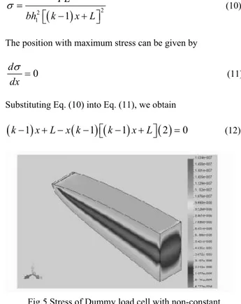
=(11) Substituting Eq. (10) into Eq. (11), we obtain
(
k
−
1
)
x L x k
+ −
(
−
1
) (
k
−
1
)
x L
+
( )
2
=
0
(12)Fig.5 Stress of Dummy load cell with non-constant cross-sectional area
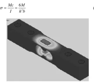
Fig. 6 Stress characteristic related with the applied force The stress of load cell as shown in Fig. 4 was analyzed using finite element method. The analysis results obtained from COSMOS simulation program are showing in Fig. 5 and Fig. 6. It is clearly seen that, Its stress characteristic is distributed uniformly over the area. Moreover, it is easy to build an actual one.
ICCAS2005 June 2-5, KINTEX, Gyeonggi-Do, Korea
3. DESIGN AND IMPLEMENTAITON OF
LOAD CELL
In this paper, the application of finite element method is used to design the shape of load cell as an illustrative case study. The experiment starts with designing and modeling load cell using CAD. Then the shape of modeled load cell is analyzed using COSMOS program. The results obtained will be further used to determine the appropriate position of strain gauge installation.
Fig. 7 Modeling of wrench design
The studied load cell to be designed is the one used to measure the torque by modeling it in the form of beam as shown in Fig. 7. For torque measurement of bolt spin should be install the load cell at the handle of wrench. The application of load cell with the proposed concept as referred in Eqs. (7), (10), and (12) for wrench design is shown in Fig. 8.
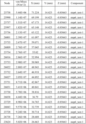
Fig. 8 Modeling of dummy load cell in wrench design From Fig. 8, the studied dummy load cell was implemented based on the use of CNC machine with 5083 aluminum as the raw material. The plies of the both ends are designed for connecting with the head and handle of the wrench. Fig. 9 and Table 1 show the COSMOS simulated result of studied dummy load cell when the applied force is about 10kg. From stress characteristic as shown in Table 1, the appropriate position to install the strain gauges is determined. The maximum stress is the importance factor for choosing. From Table 1,the appropriate positions of x are 50.96 to 65.148 mm. 4-Active gauge installations as shown in Fig.10, four 120-ohm gauges with a diameter of 5 mm are used in the experiment.
Fig. 9 Simulated stress characteristic of studied load cell Table 1 Relationships between the position x and their stress
To amplify the output signal of strain gauge, the amplifier as shown in Fig. 11 is used. Its circuit diagram is shown in Fig. 12. Fig. 13 shows the implementation of designed wrench as illustrative case study in this paper.
Fig. 10 4-Active gauge installations
Node von Mises (N/m^2) X (mm) Y (mm) Z (mm) Component
23738 5.44E+06 71.224 14.423 -0.85663 step6_test-1 25990 1.14E+07 69.199 14.423 -0.85663 step6_test-1 23737 1.51E+07 67.173 14.423 -0.85663 step6_test-1 25997 1.82E+07 65.148 14.423 -0.85663 step6_test-1 23736 2.13E+07 63.122 14.423 -0.85663 step6_test-1 26001 2.39E+07 61.097 14.423 -0.85663 step6_test-1 23735 2.67E+07 59.071 14.423 -0.85663 step6_test-1 26009 2.76E+07 57.045 14.423 -0.85663 step6_test-1 23734 2.76E+07 55.02 14.423 -0.85663 step6_test-1 26016 2.86E+07 52.994 14.423 -0.85663 step6_test-1 23733 2.90E+07 50.969 14.423 -0.85663 step6_test-1 26022 2.88E+07 48.943 14.423 -0.85663 step6_test-1 23732 2.64E+07 46.918 14.423 -0.85663 step6_test-1 26027 2.05E+07 44.892 14.423 -0.85663 step6_test-1 23731 8.71E+06 42.867 14.423 -0.85663 step6_test-1 26031 3.41E+06 40.841 14.423 -0.85663 step6_test-1 23730 5.78E+06 38.816 14.423 -0.85663 step6_test-1 26038 4.44E+06 36.79 14.423 -0.85663 step6_test-1 23729 8.98E+06 34.765 14.423 -0.85663 step6_test-1 26043 9.57E+06 32.739 14.423 -0.85663 step6_test-1 23728 9.24E+06 30.714 14.423 -0.85663 step6_test-1 26738 7.26E+06 28.688 14.423 -0.85663 step6_test-1 23624 5.02E+06 26.663 14.423 -0.85663 step6_test-1
2056
ICCAS2005 June 2-5, KINTEX, Gyeonggi-Do, Korea
50Ω 8 INA 217 1 2 3 22pF 22pF 0.1 Fµ 0.1 Fµ +12V -12V 7 4 6 3 2 LM 358 10kΩ 100kΩ 4.7kΩ 500Ω -12V +12V 8 4 1 100kΩ 0.1 Fµ I/P(+) I/P(-) 3202-C 100 Fµ+5V D3 D4 D5 S6 3 8 5 7 1 6 2 4Fig. 11 Amplifier of strain gauge output signal
Fig. 12 Circuit diagram of the amplifier
4. EXPERIMENTAL RESULTS
Fig. 13 Designed wrench in weighing system
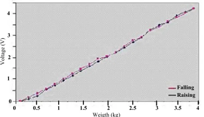
The performances of the proposed technique were studied using weighing system as shown in Fig. 13. The experimental results as the voltage signals are shown in Fig. 14, when the raising and falling varied weight (0 to 4kg and 4 to 0kg) are applied. The hysteresis error of measurement about 1.725% of span oberved.
Falling Raising 0 1 2 3 4 0 Weigth (kg) 1 2 3 4 Volt age (V) 0.5 1.5 2.5 3.5
Fig. 14 Experimental results for hysteresis test
5. CONCLUSION
The case study of shape design of load cell using finite element method is described in this paper. The experiment starts with designing and modeling load cell using CAD. Then the shape of modeled load cell is analyzed using COSMOS simulation program. The stress characteristic obtained will be further used to determine the appropriate position of strain gauges for good quality load cell. The experimental results show the good efficiency of the proposed technique.
REFERENCES
[1]
Li Erping, A L Kidd and P M McEwan, " CAD Design
of CurrenSensitive Electromagnetic Acluators",
Proceedings of 4th int. Sym. on Short-circuit Currents in
Power Systems. Liege, September 1990.
[2] The scope of the strain gage principle Bethe, K.; CompEuro '89., 'VLSI and Computer Peripherals. VLSI and Microelectronic Applications in Intelligent Peripherals and their Interconnection Networks', Proceedings.8-12 May 1989 Page(s):3/31 - 3/38
[3] William M. Murry and William R. Miller, The Bonded Electrical Resistance Strain gage, Oxford University Press,1992.
[4] Concepts and Applications of Finite Element Analysis, 4th Edition by Robert D. Cook, David S. Malkus, Michael E. Plesha, Robert J. Witt
[5] Strain Gage Users' Handbook by R. L. Hannah (Editor [6] Engineering Mechanics of Solids (2nd Edition) by Egor P. Popov
[7] Mechanics of Solid Materials by Jean Lemaitre, Jean-Louis Chaboche