ICCAS2005 June 2-5, KINTEX, Gyeonggi-Do, Korea
1. INTRODUCTION
Humanoid robots are one kind of biped robots, having the shape and ability like human being. They are well suited for working in the environment originally designed for people and coexisting with people friendly. But biped robots are one of the hardest to control, caused by instability especially during dynamic walking, and it is a challenging problem to control them. This is the reason why many researchers are working currently on the study and the development of biped robots [1-4]. The ideal humanoid robots are able to coexist and collaborate with humans and perform the difficult and dangerous works that humans can’t do [5]. In order to do these tasks, humanoid robots must have autonomous system architecture [6]. To give free mobility, their basic control system, servo system, communication system and power supply system should be mounted on the body structure. The autonomous characteristic needs the high performance of the control system. Thus the autonomous robot becomes the huge control system. It is difficult to install control units on a body. Therefore the robot specification has to satisfy both the performance and structure of the control system. In this study we will suggest a distributed control system [7-8].
Since the system needs efficient control method, fast calculation, fast communication and real-time data exchange, we suggest a new real-time message control system for a humanoid robot based on real-time distributed control system with CAN. All this process is verified by experiment.
2. BASIC CONFIGURATION
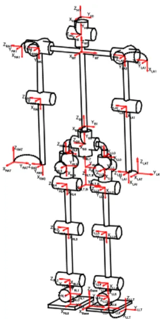
Fig. 1 shows the basic configuration of a humanoid robot with 22 DOFs, which are 6 in each leg, 3 in each arm, 2 in main body and 2 in head. Each of joints has its own control units to drive the actuator, to acquire data of sensors and to communicate with main controller.
In order to realize the real-time distributed control, two kinds of communication media are employed. One is the wireless LAN used to connect PC simulator with user
interface module in a body of the robot, and the other is the CAN, which is for communicating main controller with joint controllers. Force sensors are mounted on the feet to measure the ground reaction force and then calculate actual ZMP (zero moment point) position. Two acceleration sensors are mounted at a robot foot to measure the acceleration. And one inclinometer is mounted at a robot trunk to measure the orientation. XBase YBase ZBase XRL0 ZRL0 YRL0 XRL2 ZRL1 YRL1 XRL1 ZRL2 YRL2 XRL3 ZRL3 YRL3 XRL4 ZRL4 YRL4 XLLT ZLLT YLLT XRL5 ZRL5 YRL5 XRL6 ZRL6YRL6 XRL7 ZRL7 YRL7 XRLT,B ZRLT,B YRLT,B XLL0 ZLL0YLL0 XLL1 ZLL1 YLL1 XLL2 ZLL2 YLL2 XLL3 ZLL3 YLL3 XLL4 ZLL4 YLL4XLL5 ZLL5 YLL5 XLL6 ZLL6 YLL6 XB0 ZB0 YB0 XRA0 ZRA0 YRA0 XB1 ZB1 YB1 XBT ZBT YBT XRAT ZRAT YRAT XRA2 ZRA2 YRA2 XRA1 ZRA1 YRA1 XRA3 ZRA3 YRA3 XLAT ZLAT YLAT XH0 ZH0 YH0 XH1 ZH1 YH1 XLA0ZLA0 YLA0 XLA1 ZLA1 YLA1 XLA1 ZLA1 YLA1 XLA1 ZLA1 YLA1
Fig. 1 Coordination of a humanoid robot
Table 1 shows the brief specifications of a humanoid robot and Table 2 presents the brief specifications of a user interface module in a humanoid robot. It contains a 32-Bit embedded main controller with 64Mbyte SDRAM for supporting a
Real-time Message Network System for a Humanoid Robot
Sang-Min Ahn*, Jung-Sik Gong**, Bo-Hee Lee***,
Jin-Geol Kim****and Uk-Youl Huh*****
* School of Electrical Engineering, Inha University, Incheon, Korea (Tel : +82-32-860-8923; E-mail:[email protected]) ** Department of Automation, Inha University, Incheon, Korea
(Tel : +82-32-860-8923; E-mail:[email protected])
*** Department of Electrical Engineering, Semyung University, Chechon, Korea (Tel : +82-43-649-1305; E-mail:[email protected])
**** School of Electrical Engineering, Inha University, Incheon, Korea (Tel : +82-32-860-7384; E-mail:[email protected])
***** School of Electrical Engineering, Inha University, Incheon, Korea (Tel : +82-32-860-7394; E-mail:[email protected])
Abstract: This paper deals with the real-time message network system by a CAN (controller area network) based on the real-time distributed control scheme to integrate actuators and sensors in a humanoid robot. In order to apply the real-time distributed processing for a humanoid robot, each control unit should have the real-time efficient control method, fast sensing method, fast calculation and real-time valid data exchange method. Moreover, the data from sensors and encoders must be transmitted to the higher level of control units in maximum time limit. This paper describes the real-time message network system design and the performance of the system.
ICCAS2005 June 2-5, KINTEX, Gyeonggi-Do, Korea 3.2 User interface module
User interface module contains one CPU and many kinds of peripherals. 32-Bit low power CPU is used to interface with user, control overall operation, and its companion 32-Bit. DSP is able to do fast computation in calculation of inverse kinematics and trajectory planning job. Basically it has 64M SDRAM, additional memory can be extended using Multi Media Card. Host CPU and DSP use HPI (host port interface) protocol to transmit and receive data fast. To communicate with user interface module, main controller has wireless LAN, so user can send target position and data to the robot. 3.3 Main controller
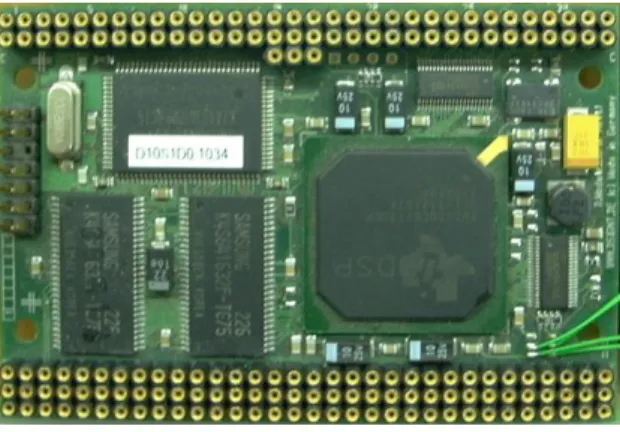
Fig. 3 shows the picture of main controller. Main controller contains high speed 32-Bit DSP with external SRAM and external SDRAM. Main controller is most important part of a humanoid robot control system. Main controller has special structure for robot control. That is the plug-in manager [11]. Plug-in manager supports basic environment for robot control plug-ins (intelligent behavior plug-in, robot stability control plug-in, vision control plug-in, ZMP control plug-in, trajectory generator plug-in, API plug-in and so on). Each plug-in operates independently each other but they can share own data using shared memory block in message controller.
Fig. 3 Main controller 3.4 Message controller
Message controller contains high speed 16-Bit DSP and 4MByte high speed external SRAM. Fig. 4 shows the picture of message controller. It communicates with local controllers in lower layer using internal CAN module and main controller in upper layer using internal real-time adapter. This controller can control message stream for transmitting the messages to its own destinations in dead time. And it also can saves data in the messages to shared memory block for support effective real-time distributed control system.
Fig. 4 Message controller
3.5 Local Controller
Fig. 5 shows the picture of local controller. High speed 16-bit DSP mounted in local controller. It have the ability to control own actuator. It also has the CAN module, A/D converter, PWM unit, pulse encode unit and so on. Additionally, it is equipped with interfacing circuit related with DC motor. The command data from main controller can be received through by CAN and the local DSP controls its motor and sensors. Two or more local controllers will have force sensor module and a gyro-sensor interface module. Local controller gets sensor data from sensors every 1ms. And the data transmit to message controller every 10ms.
Fig. 5 Local controller
4. REAL-TIME MESSAGE NETWORK SYSTEM OF A HUMANOID ROBOT
To increase stability and accuracy of robot, a robot control system must be guarantee the data transfer stability and data exchange in time limitation. But lots of low level controllers and sensors create many problems in data communication. To solve the problems, the system needs BUS type data communication method, real-time data exchanges method, multi channel communication method and high speed processing method. So we design the real-time message network system using the CAN for supporting these methods based on high speed DSP.
In order to make good humanoid control system, five characteristics have been considered.
1. Local controller must receive trajectory data for next position control in trajectory data refresh in 10ms.
2. After tracking the trajectory data, actual position data must be transmitted in 10ms.
3. All sensor data in local controllers are sent to the main controller through by message controller in 10ms.
4. Manual command from user must be transmitted to the local controllers anytime.
5. Other parts (vision part, intelligent part, etc…) in a humanoid robot system can access the shared memory block in message controller.
4.1 Trajectory data control
Local controller has to receive one message by message controller every 80ms. One message has eight byte data filed and it can include eight trajectory data. Local controller controls the actuator using extra encoder with in 1ms. And one trajectory data is refreshed every 10ms. If the local controller finishes joint control every 10ms, it send actual joint position data to message controller immediately using the CAN. Fig. 6 shows the block diagram of trajectory data stream.
ICCAS2005 June 2-5, KINTEX, Gyeonggi-Do, Korea Min : 7ns Max : Request Main Controller Local Controllers Encoder Message Controller Every 10ms Every 10ms Every 10ms Min : 10ms Max : 80ms Min : 7ns Max : Request
Fig. 6 Block diagram of trajectory data stream 4.2 Sensor data control
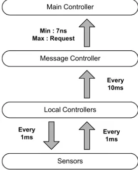
Local controllers in each joint have sensors for sensing some information: force, acceleration, shape of ground, torque of motor and so on. Local controller reads data from sensors using internal ADC in every 1ms and save the data in memory. When local controller has ten data, it starts filtering using saved sensing data. After filtering, it transfers from data format to message format and sends the message to message controller immediately using CAN. These processes occur in every 10ms. Fig. 7 shows the block diagram of sensor data stream. Main Controller Local Controllers Sensors Message Controller Min : 7ns Max : Request Every 10ms Every 1ms Every 1ms
Fig. 7 Block diagram of sensor data stream
4.3 User command data control
User can send user’s command to a humanoid robot anytime using the user interface module. This command is very important. Robot must execute user’s command immediately. But this command creates many unfixed problems like increasing instability of a humanoid robot and the message scheduling crack. Thus the maximum time limitation is needed to avoid above problems. In this system, we select the maximum time limit of 10ms. And we use independent schedule method for processing the user’s command message. Fig. 8 shows the block diagram of user command data stream. It describes that user can send command to a humanoid robot, but the system does not react immediately. Min : 7ns Max : Request Main Controller Local Controllers Message Controller Max : 10m Max : 10m Anytime
Fig. 8 Block diagram of user command data stream 4.4 Message management block
Message controller between main controller and local controller must have huge and fast memory for saving many data in messages. And it has high-speed 16-Bit DSP for real-time message scheduling. Data extract from message is saved to shared memory block by message management block. If main controller requests some data using real-time adapter, message management block sends the data to main controller immediately. This block can communicate with real-time adapter, and the real-time adapter connects to main controller using EMI (external memory interface). Many messages created by local controllers are transmitted to message manage block through the CAN. Message manage block is receives messages in every 10ms. And it sends eight trajectory data in one message to local controller in every 80ms.
5. EXPERIMENT
After design and implementation, we experiment the system. Fig. 9 shows the picture of timing of messages in one time slot. In this picture, trajectory data is transmitted from main controller to local controllers every 80ms. And main controller receives sensor data from local controller every 10ms. Table 6 shows message description of a humanoid robot. And the number of messages means own priority. We use oscilloscope and timer in DSP to measure the message time in data exchange. A message exchange time in CAN spends about 117μ sec when transmission speed is applied in 1-Mb/s. And one message has eight bytes in CAN message field. Table 7 shows result of experiment. The total length of twelve messages exchange time is 1.412ms. And the length of