Volume 2013, Article ID 814375,5pages http://dx.doi.org/10.1155/2013/814375
Research Article
A Balanced-Fed Dual Inverted-F Antenna with
Reduced Human Body Effects
Wang-Sang Lee, Hyun-Sung Tae, Kyoung-Sub Oh, and Jong-Won Yu
Department of Electrical Engineering, Korea Advanced Institute of Science and Technology (KAIST), 291 Daehak-ro, Yuseong-gu, Daejeon 305-701, Republic of Korea
Correspondence should be addressed to Wang-Sang Lee; [email protected] Received 8 August 2012; Revised 24 December 2012; Accepted 3 February 2013 Academic Editor: Safieddin Safavi-Naeini
Copyright © 2013 Wang-Sang Lee et al. This is an open access article distributed under the Creative Commons Attribution License, which permits unrestricted use, distribution, and reproduction in any medium, provided the original work is properly cited. A balanced-fed dual inverted-F antenna with reduced human body effects for WLAN applications at 2.45 GHz is presented. In order to reduce the influence by a close proximity or a touch of a human body, the proposed antenna employs an impedance matching using a lumped LC-balun which has the simple and compact structure applying for mobile handsets. The resonant frequency of the proposed antenna is fixed at 2.45 GHz regardless of the close proximity of a human body. By applying for the L-shape ground plane, the proposed antenna has the wide impedance bandwidth of about 150 MHz and the peak realized gain of about 4 dBi.
1. Introduction
Due to the several benefits such as compact and low profile structure, planar inverted-F antenna (PIFA) is most com-monly used for mobile handsets. Because the ground plane of the PIFA plays a significant role in its operation, the ground plane is an integral part of the antenna assembly [1].
PIFA has very large current flows on the ground plane. It means that the antenna characteristics are influenced by the external objects such as a human head or hand. The influences of antenna performance by human body effects for mobile handsets have been analyzed [2,3]. In order to overcome the sensitive antenna characteristics by human body effects, the balanced-fed built-in antennas with PIFA configuration in [4], folded configuration in [5], or bow-tie structure in [6] have been proposed.
However, these antennas are not easy to adjust the changed resonant frequency at the practical implementation. Therefore, in this paper, we present a dual inverted-F antenna having a balanced feed for the reduced human body effects. It is insensitive to perturbations of the ground plane and easy to control the resonant frequency by cutting the length of a folded inverted-F antenna.
2. Antenna Configurations
The geometry of a balanced-fed dual inverted-F antenna (BDIFA) is shown inFigure 1. It is fabricated on a double-sided RF35 substrate with a dielectric constant of 3.5 and thickness of 0.5 mm. The proposed BDIFA structure is com-posed of a dual folded inverted-F antenna, a lumped LC-balun for a balanced feed, and an L-shaped ground plane. By folding antenna arms, the length of one arm in the proposed antenna is an approximately 24 mm (0.196𝜆0, where𝜆0is the free-space wavelength at 2.45 GHz). It is 30 percent smaller than that of one arm in a dipole antenna.
In order to prevent the ground and human body effects, the balun which converts between a balanced signal and unbalanced signal is required. In addition, the balun can also provide impedance transformation. Due to the compact and simple structure, LC-balun known as a lattice-type balun is applied. It consists of two capacitors and two inductors, which produce the phase difference of 180 degree. The values of lumped elements in the LC-balun are 𝐿 = 15 nH and 𝐶 = 2 pF.
Figure 1shows that the proposed antenna has a balanced-fed with an LC-balun through a coaxial cable. The L-shaped
(c) 60 Ground plane 120 Feeding point 3 25 0.5 7.5 Via-hole 0.5 (b) 50 Ω coaxial cable 𝑧 𝑦 𝑥
Figure 1: Geometries and dimensions of proposed antenna: (a) top view, (b) back view, and (c) side view.
ground plane is achieved by connecting the back side of antenna element with rectangular metal plate for a wide-band characteristic [7]. The dimensions of the proposed antenna without the ground plane are 25 mm by 7.5 mm. The photograph of the fabricated antenna prototype is shown in Figure 2(a). For assessing the performance of wireless devices in real situations, hand fixture (IXB-090R) with CTIA phantom hand designed by IndexSAR is used to examine the influence of the user’s hand on frequency detuning in
Figure 2(b).
3. Results and Discussions
To investigate the electrical characteristics of the proposed BDIFA, it has been designed and analyzed using a 3D elec-tromagnetic solver (Microwave Studio by CST). Figure 3
shows the simulated and measured return losses against
(a)
(b)
Figure 2: (a) Prototype of the proposed antenna and (b) the grip of a hand fixture on the proposed antenna.
Simulated (without a hand fixture)
Measured (without a hand fixture) Measured (with a hand fixture)
Ret u rn loss (dB) 0 5 10 15 20 25 30 2.3 2.35 2.4 2.45 2.5 2.55 2.6 Frequency (GHz)
Figure 3: Simulated and measured return losses against frequency of proposed antenna.
𝑧 𝑦 𝑥 (a) 𝑧 𝑦 𝑥 (b) 𝑧 𝑦 𝑥 1 0 (c)
Figure 4: Simulated surface current directions and distributions of the proposed antenna at 2.45 GHz: (a) with in-phase, (b) with out-phase, and (c) its normalized surface current distributions on ground plane.
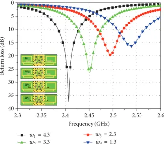
0 5 10 15 20 25 30 35 40 Ret u rn loss (dB) 2.3 2.35 2.4 2.45 2.5 2.55 2.6 Frequency (GHz) 𝑤1= 4.3 𝑤2= 3.3 𝑤3= 2.3 𝑤4= 1.3 𝑤1 𝑤2 𝑤3 𝑤4
Figure 5: Simulated return losses against frequency with a different length (𝑤) for the proposed antenna.
frequency with or without a hand fixture. The center resonant frequencies of the BDIFA in the simulation and measurement are approximately equal to 2.45 GHz. Due to the tolerance of lumped elements and parasitic effects of a radiation part, the upper frequency band becomes broaden in the measured
results. The measured impedance bandwidth (VSWR≲ 3.5) is about 150 MHz.
Regardless of a phantom hand, antenna impedance bandwidth remains unchanged because of a balanced-fed structure of the BDIFA. The surface current directions and
−20 −25 −30 −25 −20 −15 −10 −5 0 5 M easur ed radia tio n pa tt er 270 240 210 180 150 120 90 𝑧 𝑦 𝑥 𝐸𝜙 𝐸𝜃 (a) −20 −25 −30 −25 −20 −15 −10 −5 0 5 M easur ed radia tio n pa tt er 270 240 210 180 150 120 90 𝑧 𝑦 𝑥 𝐸𝜙 𝐸𝜃 −50 −55 −60 −55 −50 −45 −40 −35 −30 −25 (b) 5 0 −5 −10 −15 −20 −25 −30 −25 −20 −15 −10 −5 0 5 M easur ed radia tio n pa tt er n s (dB i) 0 330 300 270 240 210 180 150 120 90 60 30 𝑧 𝑦 𝑥 𝐸𝜙 𝐸𝜃 (c)
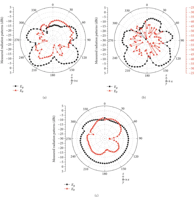
Figure 6: Measured radiation patterns at 2.45 GHz: (a)𝑥𝑧 plane, (b) 𝑦𝑧 plane, and (c) 𝑥𝑦 plane.
distributions on the ground plane at 2.45 GHz are shown in Figure 4. In order to compare the current directions according to the phase difference between the two folded arms, Figures4(a)and4(b)show the in-phase and out-phase, respectively. In case of out-phase folded arms, small current flows are observed on the ground plane, and it means it is less sensitive to perturbations of the ground plane.Figure 4(c)
shows the normalized surface current distributions on the ground plane, where the darker color indicates larger current flow. As a result, the human body effects can be reduced.
Figure 5shows simulated return losses against frequency with a different length (𝑤) for the BDIFA. By controlling the length of radiation arms (𝑤), the resonant frequency can be tuned.Figure 6shows the measured radiation patterns of 𝑥𝑧-plane,𝑦𝑧-plane, and 𝑥𝑦-plane at 2.45 GHz, respectively. The
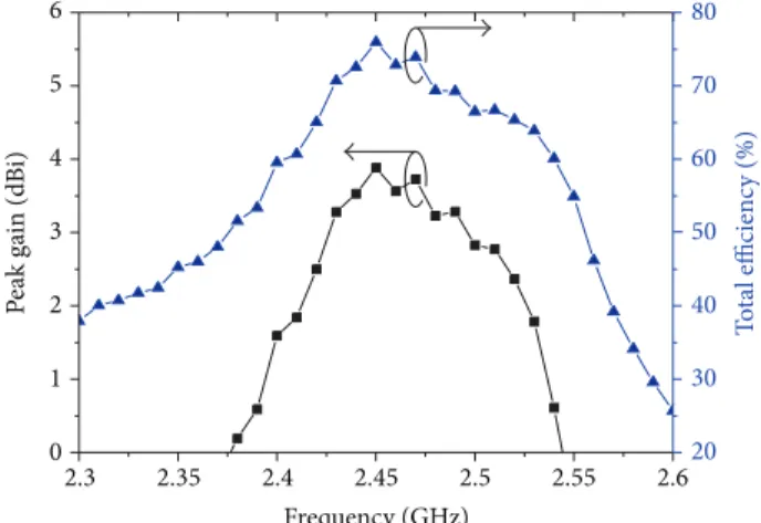
measured results show that the radiation patterns at vertical planes of𝑥𝑧-plane and 𝑦𝑧-plane are conical, and in horizon-tal plane, the pattern is nearly omnidirectional. InFigure 7, the measured peak realized gain against the frequency is shown. The maximum peak realized gain is about 4 dBi at the center frequency, 2.45 GHz. Furthermore, an experimental investigation has also been carried out with regard to the overall antenna total efficiency inFigure 7. Within the operat-ing frequency, the maximum overall antenna total efficiency has approximately 75%.
4. Conclusion
A compact low-profile dual inverted-F antenna with a bal-anced feed is presented. The proposed antenna is not only
6 5 4 3 2 1 0 P eak ga in (dB i) 2.3 2.35 2.4 2.45 2.5 2.55 2.6 Frequency (GHz) 80 70 60 50 40 30 20 T o ta l efficienc y (%)
Figure 7: Measured peak realized gain and antenna total efficiency with regard to frequency.
compact and low-profile configuration but also insensitive to the influence of human body effects for the practical WIFI applications. The impedance bandwidth and peak realized gain of the proposed antenna have approximately 150 MHz and 4 dBi, respectively. It can be suitable for practical WLAN applications in mobile handsets.
Acknowledgment
The authors would like to gratefully acknowledge the techni-cal support by Korea Testing Laboratory (KTL).
References
[1] M.-C. Huynh and W. Stutzman, “Ground plane effects on pla-nar inverted-F antenna (PIFA) performance,” IEE Proceedings:
Microwaves, Antennas and Propagation, vol. 150, no. 4, pp. 209–
213, 2003.
[2] K. Ogawa, T. Matsuyoshi, and K. Monma, “An analysis of the performance of a handset diversity antenna influenced by head, hand, and shoulder effects at 900 MHz. Part I. Effective gain characteristics,” IEEE Transactions on Vehicular Technology, vol. 50, no. 3, pp. 830–844, 2001.
[3] C. H. Li, E. Ofli, N. Chavannes, and N. Kuster, “Effects of hand phantom on mobile phone antenna performance,” IEEE
Tran-sactions on Antennas and Propagation, vol. 57, no. 9, pp. 2763–
2770, 2009.
[4] K. Ogawa, H. Iwai, and Y. Koyanagi, “Balance-fed planar built-in antenna,” Electronics Letters, vol. 37, no. 8, pp. 476–478, 2001. [5] D. Zhou, R. A. Abd-Alhameed, C. H. See, A. G. Alhaddad, and P. S. Excell, “Compact wideband balanced antenna for mobile handsets,” IET Microwaves, Antennas and Propagation, vol. 4, no. 5, pp. 600–608, 2010.
[6] J. Ilvonen, J. Holopainen, O. Kivek¨as, R. Valkonen, C. Icheln, and P. Vainikainen, “Balanced antenna structures of mobile terminals,” in Proceedings of the 4th European Conference on
Antennas and Propagation (EuCAP ’10), April 2010.
[7] W. S. Lee, K. J. Kim, D. Z. Kim, and J. W. Yu, “Compact fre-quency-notched wideband planar monopole antenna with a L-shape ground plane,” Microwave and Optical Technology Letters, vol. 46, no. 6, pp. 563–566, 2005.