409 Journal of International Conference on Electrical Machines and Systems vol. 3, no. 4, pp. 409~414, 2014
Switched Reluctance Motors for Electric Drive of Overland Belt
Conveyor
G.K. Ptakh *, N.F. Evsin **, D.A. Zvezdunov **, D.V. Rozhkov *, and A.E. Yakovenko *
Abstract -
The parameters and operating characteristics of the switched reluctance motor (SRM) for the electric drive of the overland belt conveyor CLM-4500 have been presented. The motor power capacity has been equal to 1250 kW, the motor speed - 1000 min-1. SRM power supply has been provided by a three-phase voltage inverter and a 12-pulse rectifier circuit. The group electric drive has been installed on sections number 2 and 3, 3770 m and 3375 m length, respectively, on the areas of "Berezovsky Strip" JSC, a member of the Siberian Coal Energy Company.Keywords: Switched Reluctance Motor, Electric Drive, Overland Belt Conveyor
1. Introduction
The first SRD for industries with poor working conditions was used by the British company “Jeffrey Diamond” [1]. In 1998 the company established the SRM on a belt conveyor, 2.3km length, on the Maltby Collieey mine (UK).
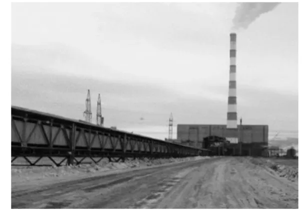
Fig. 1. Coal deliveries for Berezovskaya GRES using the overland belt conveyor CML-4500 (stack height of 370 m)
Since 2012, the "VIEM" Ltd. has been developing a high power SRD for the Siberian Coal Energy Company (SUEK). SUEK ranks first in Russia in coal production and is surely one of the largest mining companies in the world. In 2013, the production volume was 96.5 million tons, nearly half of which has been exported. The company employs more than 30 thousand people. SUEK adopted a plan of modernization of electric main and auxiliary machinery by replacing the DC
machines and unregulated AC induction motors with SRD. As a part of this program an overland belt double-groove conveyor CLM-4500 is being modernized, a with a total length of about 15km, that provides delivery of brown coal from the mine to Berezovskaya GRES, Krasnoyarsk region (Fig. 1).
For this project a SRM with power capacity of 1250 kW at rated motor speed of 1000 min-1 has been developed to replace unregulated AC induction motors with a wound rotor like AKDZ-16-62-6U3 with power capacity of 1600 kW. The installed capacity of the SRM has been reduced because the unregulated AC induction motors’ power capacity for the starting torque has been overestimated.
2. Purpose and Characteristics
The SRD application to control the drive stations of the belt conveyors: increases energy efficiency; reduces operating costs; smooth start and stop motors; reduces dynamic loads in the motor drive and in the traction system in the operation mode and congestions; increases the availability factor; raises the technical level of belt conveyors through automation drive stations, diagnosis quality improvement and protection of electrical circuits; improves reliability, increases service life and life of the process equipment; implements the repair mode at reduced speed without an additional actuator with reduced gear box.
3. Design Parameters
Structurally, the active part of the ID-1250-1000 has been inserted into the body of AKDZ-16-62-6U3 that allowed using
* Platov South-Russian State Polytechnic University (NPI), Russia, ([email protected])
** "VIEM" Ltd., Russia ([email protected])
the existing bodies and preserving the overall and mounting dimensions to reduce operating costs.
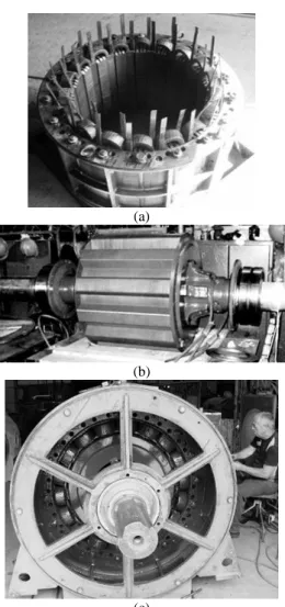
Photos of the stator, rotor and assembled engine with removed covers on the front bearing plate are shown on Fig. 2..
Basic parameters of the ID-1250-1000 are as follows: the outer diameter of the stator package - 1180 mm; the bore diameter of the stator package - 830 mm; the air gap - 2 mm; the length of the stator package - 635 mm; the number of stator/rotor teeth - 18/12; the number of phase – 3; the number of autonomous phase branches - 3; the winding insulation class - H; the motor protection class - IP21; the cooling system - forced air axial; the engine weight - 8200 kg. The stator has been assembled from segments (6 pieces in one layer) with ventilation channels, and a rotor – of solid sheets of electrical steel 2412 0.35 mm thick.
(a)
(b)
(c)
Fig. 2. Switched Reluctance Motor ID-1250-1000: a-stator package with winding of a coil type; b-rotor; c-assembled motor
The turn and frame insulations have been made of mica impregnated tape Elmikaterm 529029, the coating insulation has been made of glass fiber tape LES. The slot insulation has been made of Poromat 2248 produced by the ISOVOLTA AG
company (Austria). This type of insulation expands by 150% after a vacuum impregnation with varnish KO-916H, eliminating air gaps.
4. Inverter Power Supply
The typical power circuit of the SRM phase is a voltage half-bridge inverter (unbalanced bridge) that usually stocks on choppers. Since manufacturers of power electronics do not produce choppers for currents of more than 1000 A, even though they are presented in directories, then to build the voltage inverter, the IGBT modules of 17th class-type PrimePACK for 1400A have been selected. These modules are produced by companies Fuji (Japan) and Infineon (Germany). In ID-1250-1000 each phase is split into three distinct branches. A parallel connection of branches has not been applied, since it also require the parallel connection of IGBT-switches. In this case it would be necessary to introduce 20% of the current margin. We explain the principle of controlling the IGBT-inverter switches that supply one phase power motor branch (Fig. 3).
Fig. 3. Voltage inverter’s bridge circuit to power and control one phase branch SRM-1250-1000
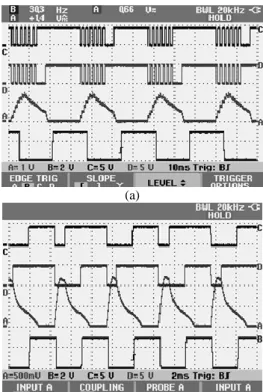
When powering and controlling the high power SRM, there are two basic modes: the mode with PWM regulation voltage at the start and low rotation speeds (Fig. 4,a) and the main working-pulse power mode of the SRD (Fig. 4,b).
IGBT-switches control signals are generated on the bases of the incoming signal for this phase from the rotor’s position indicator. The reference point (a zero angle) of the rotor position has been taken relative to the stator, wherein the axis of the considered phase stator tooth coincides with the axis of the rotor slot. The IGBT-switch is closed if the control electrode receives a signal of +5 V, the IGBT-switch is open if the level of the control signal is 0. The control is exercised by switches VT1 and VT4. In terms of one period three time intervals can be distinguished: 1 - when both switches are open (turned on), the energy for creating the torque is generated by the charged capacitor and the source of the DC voltage Ud; 2 - when one switch is locked (turned off): the inductance locks on itself, the current is reduced and the torque is generated by reducing the magnetic energy stored in the inductor; 3 - when
both IGBT-switches are locked (turned off), then the remaining part of the magnetic power in the inductance returns to the source and the capacitor until the current reaches zero. For the uniform current and accordingly thermal loads of wheeling diodes VD2 and VD3, the sequence of locking VT1 and VT2 changes every period (Fig. 4). IGBT-VT2 and VT3 switches are locked (turned off).
(a)
(b)
Fig. 4. Oscillograms, explaining the operation of the inverter circuit Fig. 3: a– operation in WIDE mode on low speeds (n = 143 min-1); b-operation in pulse mode (n = 770 min-1); A-phase current; B-signal to a rotor position indicator; C-control signal IGBT-switch
VT1; D - control signal IGBT-switch VT2
5. Block diagram of the power supply of the SRM
group electric Drive CLM-4500 number 2
The block diagram of the power supply of the group electric drive is shown in Fig. 5. In order to reduce the impact on the quality of the uncontrolled rectifier on the voltage, the 12-pulse rectification circuit with a series of connected rectifiers has been adopted. To implement this scheme on a tail section a three-winding transformer TRSZP-3,2-10/0.4 (3.2 MVA) (with a split secondary winding) has been set, which reduces the voltage from 10 kV to 0.4 kV. In this case, in the primary winding transformer the 5th and 7th harmonic currents are excluded that significantly reduces the negative impact of the converter load on the quality-voltage of a high-voltage network. A series connection of the rectifier provides a link tothe DC voltage of 1000 V, which then with the help of voltage inverter is converted to variable voltage of variable frequency. On the main section two two-winding transformer TSZP-3,2-10/0.4 have been set, which secondary-windings are connected in different ways (TV2 - "triangle", TV3 - "star"). Thus, these transformers also perform the 12-pulse rectifier circuit similar to the tail is section.
Three-phase inverters have been collected under the scheme of the asymmetrical half-bridge on each phase branch (Fig. 5). The operation principle of such a half- bridge is described above. At the inverter input a capacitor filter has been installed, with which the SRM exchanges reactive power.
Fig. 5. Block diagram of the SRM for electric drive CLM-4500 number 2: QS1 ... QS3 - vacuum circuit breakers: TV1 - three winding transformer TRSZP-3,2-10 / 0.4; TV2 and TV3 - double-wound transformers TSZP-3,2-10 / 0.4; QS4 ... QS7 - manual switches (breakers); FU1 ... FU4 - fuses;
VP1…VP8 - three-phase bridge uncontrolled rectifiers 12-pulse rectifier circuit; F1 ... F4 - power capacitor filters; IN1 ... IN4 - voltage inverter;
SRM1 ... SRM4 - three-phase switched reluctance
motors
6. SRD group Dynamics at the Start of CLM-4
500 number 2
Fig. 6. Kinematic diagram of CML-4500 number 2: D1 ... D3 driving drums; D4 - presser drum; D5, D6 - bypass drums; D7 - head drum; D8, D9 - deflecting drums; D10 – capstan
Fig. 6 shows the kinematic scheme of the belt conveyor CLM-4500 number 2 having a four-engine electric drive
group with three drive drums. The torque transmission on the drums from the SRM is realized through helical gearboxes. On the first drive drum, two SRM work on one gear, on the second and the third drums single-motor drives have been used.
One of the main advantages of the frequency-controlled electric drive is a smooth motor start without significant torque fluctuations. This improves operating conditions of the belt conveyor, which has a relatively high cost of repair and leads to breakages at significant higher operating expenses. When designing tasks for the torque and the PID-regulator’s parameters, we should take into account the elastic properties of the belt conveyor and ensure correct and safe operation of the tensioning device. Safe operation of the tensioning device depends on prompt inclusion of the electric drive on the tail section and the growth rate of its rotation frequency. If the tail drive does not manage to pull the tape, then the load of the tensioning device may fall to the ground, but if the tail drive pulls the tape with more than acceptable speed, the load can literally carry the roof of tension tower away.
The overland belt conveyor CLM-4500 consists of two separate parallel conveyors (lines) of 14.8 km length each. In return, each of the belt conveyors is divided into five reloading sections: belt conveyors number 1, 1a - 3 km length; belt conveyors number 2, 2a - 3.8 km; belt conveyors number 3, 3a, and number 4, 4a - of 3.4 km length each; belt conveyors number 5, 5a - 1.2 km. According to the project all belt conveyors parts have been driven by asynchronous slip-ring motor that powered from the network of 10 kV 50 Hz. Modernization of the CLM-4500 has been launched with the first belt conveyor line with the longest area of the section number 2, 3770 m length.
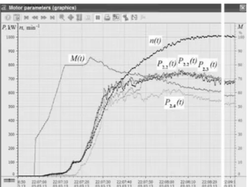
Fig. 7. Dynamics of starting CML-4500 number 2 with a fully loaded conveyor
The CLM-4500 starting has been made without coal, beginning with the fifth section. However, during the coal shipment for technical reasons or because of an accident there is a chance of stopping the coal conveyor, and then starting the already laden belt conveyor with coal. Thus, the group electric drive must provide the start of the belt conveyor at its full load
with coal. Fig. 7 shows the graphs of the time reference, the speed of one of the motors of the first drive drum and the capacity of each motor drive, which illustrate the dynamics of starting of a fully loaded conveyor CLM-4500 number 2.
The graphs show that the smooth start-up has been provided, the start of the motor on the fourth tail section has been provided with a slight delay. The start time has been 70 sec. On the main section the motors have been loaded in a similar way.
The graphs show that the smooth start-up has been provided, the start of the motor on the fourth tail section has been provided with a slight delay. The start time has been 70 sec. On the main section the motors have been loaded in a similar way.
The graphs in Fig. 7 have been obtained from the computer screen located on the central control panel of CLM-4500. This information has been transferred from the local automated control system (ACS), located on the modernized section number 2. Local ACS has had a connection with the existing control system "Granite" and with the central control panel.
7. Energy Efficiency of the SRD group and Qu
ality of Supply Voltage
The energy efficiency of the belt conveyor transport is determined by two main factors. The first factor is an uneven loading of the belt conveyor. Technological pause of shearers and emergency shutdowns, periodic change in speed, their movements are the main causes of uneven loading of the belt conveyor. The underutilized and idle belt conveyor modes are inefficient and lead to an increase energy consumption. The second factor is the operation of the belt conveyor at reduced capacity, which is mainly determined by the belt conveyor underutilization. Increased loading of the belt conveyor up to the nominal reduces some of unproductive expenditures.
Fig. 8. Comparative evaluation of energy efficiency of sections CML-4500 SRM or asynchronous motors To evaluate the power consumption efficiency of external belt conveyor lines CLM-4500 after modernization of their electric drives and control systems by the "Eco-Prog" Ltd. (Moscow) through the request of the SUEK Company the
instrumental measurements of belt conveyor lines CLM-4500 number 2 and 3 with SRM and CLM-4500 number 2A and 3A with asynchronous electric drives at different loading of belt conveyors have been conducted. The results of these studies for the period from 20.05.2014 till 30.05.2014 are presented in Fig. 8.
Despite the fact that the motors AKDZ-16-62-6U3 1600 kW with a wound rotor have been directly connected to the high voltage network of 10 kV and ID-1250-1000 has been connected to the network via the transformer and the converter, the energy efficiency of the SRD has been higher. Specific (per ton) power consumption (per unit length of the belt conveyor section) for the upgraded areas with SRD has been less than on areas with parallel asynchronous electric drives. Fig. 8 shows the dependence of energy consumption on the belt conveyor capacity due to its load. According to available statistics the average capacity of the CLM-4500 is approximately 60% from the nominal 4500 tons/h. With the capacity increase up to the nominal the 20-25% of the electric power can be saved. Modernization of all five sections of the CLM-4500, as well as of the belt conveyor transport which supplies the belt conveyor with coal must be performed to implement the optimal operation of the conveyor at the variable traffic flow.
Also it should be noted that the SRD reduce the reactive power in the network (power factor below 0.96) compared with the drive AKDZ-16-62-6U3 (power factor of 0.8).
The technical diagnostics center "Nazarovskoye GMNU" LLC, Krasnoyarsk Region, conducted a survey of the SRD power supply system on the section number 2 CLM-4500. The results of the survey at operation of the loaded belt conveyor CLM-4500 number 2 are shown in Table 1, which shows that the voltage distortion caused by the operation of the 12-pulse rectifier circuit has been within acceptable limits.
Table 1. The results of voltage quality high-voltage network Name parameter Parameter value Transformers Setpoint TV1 TV2 TV3 "War-ning" "Atten-tion" Power, kW 568 1005 997 - - Voltage, kV 9,61 9,35 11,0 12,0 Current, А 35,6 64,7 64,2 - - Factor harmonics, % 3,72 4,89 7,0 8,0 Asymmetry voltage, % 0,25 0,27 2,0 3,5 Asymmetry currents,% 4,72 1,58 2,25 10,0 20,0
8. Implementation
Group SRD of four motors ID-1250-1000 (Fig. 9) was commissioned in February 2013 in a trial operation to the
"Berezovsky Strip" JSC, Krasnoyarsk Region, Russian Federation, that supplies lignite for Berezovskaya GRES.
The implemented development has been executed by "VIEM" Ltd., Novocherkassk, under the guidance and participation of the SRSPU (NPI) scientists and experts.
Fig. 9. Switched Reluctance Motors ID-1250-1000 in the motor Room of the CML-4500 number 2
According to the results of the SRD CLM-4500 number 2 trial operation in order to reduce losses in the pressure ring rotor design modification has been carried and reduction of the air gap has been made. After the first SRD operation turn, the
Customer decided to upgrade all electro drives on other sections of CLM-4500 with its full completion in 2015. In April 2014, commissioning operations were completed and the SRM at the section number 3 CLM-4500 of 3375 m length was commissioned, and in September 2014 commissioning of the SRD on the section number 4 CLM-4500 of 3405 m length has been scheduled. After completion of electric drives replacement on all sections of CLM-4500 an automated top-level controls of all "Berezovsky Strip" belt conveyor transport is planned to be installed.
The SRM production technology is simple. Therefore, the SCEC company decided to organize its own production on the basis of Borodino repair and engineering plant LLC, Krasnoyarsk Region. This solution allows getting the cooperation deliveries away and taking up all the profit of Mechanical Engineers. Using old bodies of the DC machines and induction motors reduces the SRM manufacturing costs.
9. Conclusion
1. An operation experience of switched reluctance electric drives on the overland belt conveyor "Berezovsky Strip" during the lignite transportation showed their high performance potential. For the full year of operation at the section number 2 CLM-4500 there was not a single case of
rush or scoring of the belt conveyor expensive tape, that has been already worn-out enough.
2. The experience of our team of developers and suppliers of the switched reluctance motors 0,1 kW/12000 min-1 to 2000 kW/200 min-1 has shown that the production of these machines can be arranged on any Electric Machine Factory, which has necessary machinery and crane equipment. For two years and a half, at the electric repair factories of Russia 18 SRM with total power capacity of 17.6 MW have been managed to develop, manufactured and delivered to the Customer.
References
[1] D. Pulle, J. Lai, J. Milthorpe, N. Huynh. Quantification and Analysis of Acoustic Noise in Switched Reluctance Drives. EPE-93 Brigton, 13-16.9.1993, pз. 65-70.
Ptakh Gennady received the degree of doctor of engineering in the SRSPU (NPI). His research interests are electric machines and power systems.
Evsin Nicholas received the degree of candidate of engineering in SRSPU (NPI). His research interests are electric machines and power systems.
Zvezdunov Alex graduated from the University of Rostov Railways. Received an engineering degree. His research interests are electric machines and power systems
Pozhkov Dmitry completed graduate studies in the SRSPU (NPI). His research interests are electric machines and control systems.
Yakovenko Alexander completed graduate studies in the SRSPU (NPI)/ His research interests are electric machines and control systems.