2553
Copyright ⓒ The Korean Institute of Electrical Engineers
Study on Soft-Switching Transformers Inductor Boost Converter for
Fuel Cell Powered Railway Vehicle
No-Geon Jung* and Jae-Moon Kim
†Abstract
– In Korea, there are no instances where a hydrogen fuel cell power generation system has been used in a railway vehicle. Only the basic topology has been studied. In the previous study, conventional converters using a single switch were applied to the fuel cell power generation system. Therefore, current stress on the switch at converter on-off transitions would be large when controlling a large-capacity railway vehicle. In addition, since the input side ripple is also large, there is a problem with a shortening of the lifetime of both the fuel cell power generation system and the inductor. In this paper, a soft-switching transformer inductor boost converter for fuel cell powered railway vehicles was proposed. A technique to reduce both the switching current stress generated during on-off transitions, and the input ripple current flowing in the inductor were studied. The soft-switching TIB converter uses a transformer-type inductor to configure the entire circuit in an interleaved method, and reduces both input current ripple and the current ripple of the inductor and switch.Keywords:
Fuel cell, TIB converter, Power conversion, Railway, Soft switching1. Introduction
The transportation efficiency of electric railways is higher compared to both aircraft and ships. So it can be save energy consumption according transportation. [1-3]. However, the initial investment cost is high, due to the requirements of electric railway lines and vehicles. The researchers study continuous to apply new and renewable energies to railways, to maximize these advantages and to compensate for any shortcomings. Among these new and renewable energy sources, the fuel cell system is the most efficient, has less noise, and is the most environmentally friendly. In addition, it is easy to configure a system that is suitable for powering railway vehicles. Further, hydrogen can be continuously supplied through the fuel tank, enabling uninterrupted power generation. It is also considered to be the only portable power device currently available among new and renewable energy sources. The cost of the overall system and maintenance reduce if fuel cell power system connected to a railway vehicle is used. This is because the railway vehicle can be operated without a structure. However, fuel cell power generation has nonlinear characteristics due to polarization caused by chemical reactions, unlike DC power sources such as batteries and so on. Further, fuel cells have low output voltage characteristics. Due to these characteristics, fuel cell power generation systems require a step-up converter to supply the required voltage safely [4-5]. In Korea, there
are no instances where a hydrogen fuel cell power generation system has been used in a railway vehicle. Only the basic topology has been studied. In the previous study, conventional converters (using a single switch) were applied to the fuel cell power generation system. Therefore, current stress on the switch at converter on-off transitions would be large when controlling a large-capacity railway vehicle. In addition, since the input side ripple is also large, there is a problem with a shortening of the lifetime of both the fuel cell power generation system and the inductor [6-7].
In this paper, a soft switching transformer inductor boost converter for fuel cell powered railway vehicles was proposed to solve these problems. A technique to reduce both the switch current stresses generated during on-off transitions, and the input current ripple flowing in the inductor were studied. The soft-switching TIB converters use a transformer-type inductor to configure the entire circuit in an interleaved method, and these reduces both input current ripple and the current ripple of the inductor and switch.
2. TIB Converter of Soft Switching Method
Fig. 1 shows a soft switching TIB(Transformer Inductor Boost) converter. The circuit was designed to control the basic step-up converter using an interleaved method. For the input power source (VIN), since the voltage of the fuel cell is DC voltage, a DC voltage source was used. In this circuit, two input inductors were configured in the form of a transformer. In this paper, the applied inductor method was defined as the transformer inductor, and each phase† Corresponding Author: Dept. of Transportation System Engineering, Korea National University of Transportation, Korea.
* Dept. of Electrification System Research Team, Korea Railroad Research Institute, Korea. ([email protected])
was divided into an A and B phase. In addition, the snubber capacitors CS1 and CS2 were configured for the soft switching of IGBT S and 1 S . This did not allow current 2 to flow through the switch via the reflux of the capacitor. Further, a DC-Link which is the input voltage of the inverter was connected to a capacitor having a larger capacity (CDC) than the snubber, to reduce the ripple on the output
voltage of the converter.
2.1 Transformer Inductor (TI) ripple reduction mode analysis
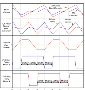
Fig. 2 shows the waveform of the ripple reduction mode of a boost converter using a TI(Transformer Inductor). The ripple current can be reduced compared to the conventional interleaved converter due to the magnetizing current generated between each inductor when using TI. In this paper, a step-up converter using a TI is called a TIB converter.
Fig. 3 shows the equivalent circuit of the TI converter without the snubber capacitor. The circuit with the snubber was removed to analyze the ripple reduction mode. The TI was a transformer type inductor. Here, V due to m L m
was generated due to the flux current, generated by the currents of the A and B phases flowing to the respective leakage inductances of L and a L . b
Regardless of the mode, the current ILm flowing in L m
is caused by the difference between the currents of the A and B phases, as shown in figure 2 The related equation is (1).
Lm LA LB
I =I -I (1)
The flux voltage calculated using (1) is shown in (2).
(
)
Lm m Lm m LA LB d d V L I L I I dt dt = = - (2)Further, since the dotted terminal of the transformer of TI is opposite, the voltages VLA and VLB applied to each
phase are expressed by (3) and (4).
LA A Lm
V =VL +V (3)
LB B Lm
V =VL -V (4)
It can be seen that the ripple of the inductor current (of each phase generated in (3) through (4)) is smaller than the ripple of the current in the interleaved inductor without using TI, as shown in figure 2. This is because the magnetic flux flowing in L acted in the opposite direction when m
the current flowed in the A and B phases. 2.2 Soft switching (ZCS) mode analysis
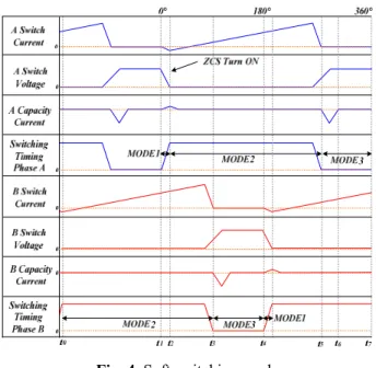
Fig. 4 shows the A and B phase modes of the proposed ZCS(Zero Current Switching) TIB converter. ZCS method is that operate switching when current is zero.ZCS method is that operate switching when current is zero. In the control method mentioned above, the two-phase interleaved method controls switches S and and1 S , so that they are 2 180° apart from each other. The mode can be divided into modes 1, 2, and 3 in each phase. Since the mode of phase B is 180° different from phase A, only phase A is presented in this paper.
2.2.1 Phase A Mode 1 (t1£ £t t2): S = OFF → ON 1 Mode 1 operates when the switch is turned on. That is, the time corresponding to the slope of the gate voltage
Fig. 1. Soft-switching TIB converter
Fig. 2. TI ripple reduction mode waveform
rising from zero. When switch S is turned on, the current 1 is discharged from the snubber capacitor CS1 (charged from the input voltage VIN) toward the output load. Because the discharging time is very short, the design of snubber capacitor CS1 is very important.
The discharge time of the voltage accumulated in the snubber capacitor CS1 varies, depending on the resistance load on the output side. Generally, when the switch is turned off is a very short time period, so it is calculated at a cycle of approximately 10 times the switching frequency. This is determined by the time constant t , as shown in (5).
1 S RC
t= (5)
The snubber capacitor CS1 (charged at the time when the switch is turned off) is discharged when the switch is larger than the current LLA when the switch is turned on
(t1~t ), and the current 2 ICS1 flowing is as shown in (6).
(
)
1 1 1 2 1 CS CS S LA dv I C i t t dt æ ö =ç = ÷× -è ø (6)When the capacitor is completely discharged, voltages 1
CS
v and V are equal, and the current does not flow. 0 In this paper, the power converter was operated at about 30% of the designed power, because the load is applied by using the induction motor. This causes ZCS to turn on.
2.2.2 Phase A Mode 2 (t2£ £t t6): S = ON 1
In this mode, the TIB converter operates with the same principle as a general interleaved boost converter. When
1
S is conducting, the input voltage VIN stores energy in the phase A inductor of TI, at which time snubber CS1 is also charged. Capacitor CDC of the DC-Link discharges through the resistor.
Since each phase is connected in parallel, the current flows by 1/N, and the voltage applied to the inductor is given by (7). 2 1 2 in LA A I E L N æ ö = ç ÷ è ø (7)
Switch S is turned on to charge the inductor. At this 1 time, diode D is turned off, and inductor 1 L increases A
linearly with the current flow, and operates as shown in (8).
(
6 2)
IN LA A V di t t dt = L - (8)2.2.3 Phase A Mode 3 (t6£ £t t8): S = OFF 1
Like Mode 2, this operates on the same principle as the discharge of a typical interleaved boost converter. When switch S is turned off, the input voltage V1 IN discharges the energy charged in the phase A inductor of TI through the output load. Further, When switch S is turned off, 1 the capacitor is charged when TI is discharging, which operates as shown in (9).
(
)
1 7 6 1 t LA CS S I V t C = × - (9)At this time, the charging operation is stopped at time (t ) (when the capacitor is fully charged), and all the 7 current charged in the inductor is transferred to the load. In this case, it operates on the same principle as a normal interleaved boost converter, and is expressed by Equation (10).
(
6)
IN O LA S A V V di t t dt L -= - (10)When the turn-off state (t6~t ) is finished, the ZCS 8 turns on again, after the charged current is discharged by returning to mode 1.
3. TIB Converter Simulation Applying Soft
Switching Technique
To verify the performance of the TIB converter, the simulation was performed in comparison with a converter using a different method. Through this, the ripple reduction effect of TIB converter was analyzed. The TIB converter was also applied to the output of the fuel cell modeling to confirm the operation of the fuel cell rail vehicle system. 3.1 TIB converter
Fig. 5 shows the circuit diagram of the TIB converter
using the soft switching technique proposed in this paper. A transformer type inductor (TI) was used. A capacitor was connected to the switch, in the form of a snubber, to configure the switch ZCS to turn on.
The snubber capacitor value for soft switching was determined by the time during which the voltage stored in the snubber capacitor CS was discharged. This was due to the load on the output side (which is usually a very short period of time), during which the switch is off and the switching frequency is not very fast, so it is calculated to be about 50 times the switching frequency.
Therefore, the capacitor CS, according to the calculation formula, is 10 [ nF ]. Table 1 shows the design values of the major devices.
As shown in figure 5, the simulation was performed with a leakage inductance of 2[mH], and magnetization inductance of 2[mH], for each phase in the ideal transformer.
The input inductor L was composed of a two phase circuit, using a TI. Two switches were also used, and a soft switching capacitor was connected in snubber mode in parallel with each switch.. The output capacitors were 680 [μF] like the abovementioned converters, and the circuit was configured to share at the point where the circuits meet. Further, the load was simulated at 1.5[kW], which is 50% of the maximum design value. The simulation was performed by PWM voltage/current control of the boost converter. The reference voltage was calculated as 380 [V], which was the input voltage of the inverter, as well as that of the interleaved converter using the snubber. When the power semiconductor device was turned on, the step-up converter transferred the input voltage to the output voltage. Control was performed so that the PWM phase of each switch had a 180°difference.
Fig. 6 shows the inductor current for each phase of the
snubber, applied to the TIB converter. It was confirmed that the ripple of the inductor current was reduced, due to the decrease in magnetization inductance when the current in each phase increased.
3.2 Comparison with conventional converters
Fig. 7 shows a comparison of the input of each snubber converter and the current of each phase. A comparison of input currents (IIN) shows that the ripple was approximately 4[A] for a conventional converter with a snubber, and approximately 3[A] for an interleaved converter with a snubber and a TIB converter. The input ripple of the interleaved converter and the TIB converter were almost the same, but the ripple currents were approximately 3[A] and 2.3[A], respectively, and the ripple of the TIB converter was approximately 23% less.
3.3 Simulation of a fuel cell powered railway vehicle with a TIB converter
Fig. 8 shows a schematic diagram of a fuel cell powered railway vehicle simulation using a TIB converter. The fuel cell modeling was the input, the inverter and the traction motor were connected in series with the TIB converter, and the bi-directional battery was connected in parallel to the DC-Link.
Modeling of the fuel cell power generation system was
Table 1. Design values of the major devices Parameter Design value Total capacity 3[kW] Input Voltage 100[V] Boost Converter Output Voltage 380[V] Inductor 2[mH] Capacitor 680[mF] Snubber Capacitor 10[nF]
Fig. 5. Simulation circuit diagram of a TIB converter using
the soft switching technique
Fig. 6. Input current of each phase of the snubber applied
to the TIB converter
Fig. 7. Converter-specific input and current comparison of
designed through a buck converter. Modeling was performed using ohmic polarization, which displays linear characteristics. Modeling was achieved by controlling the power of the step-down converter, so that the voltage decreased as the current increased, as shown in figure 9.
Fig. 10 shows the current of the TIB converter A on the fuel cell power railway vehicle. It was confirmed that the topology in which the ripple of the inductor current was reduced by applying the magnetization inductance, decreased as the current increased in each phase.
Fig. 11 shows the DC-Link voltage control of a fuel cell powered railway vehicle. The DC-Link voltage was controlled at 380[V], through the TIB converter. The voltage control performed well, although the ripple component of the voltage existed due to the load increase caused by the speed control. In addition, transient control was performed at the start of the simulation, and voltage spikes occurred
due to the capacitor charging in the DC-Link. However, this control was performed according to the voltage command of the RAMP function within 0.1[s].
Fig. 12 shows the voltage and current of the phase A switch of the TIB converter, at a steady speed of 1000[rpm]. In order to confirm that the ZCS turn-on was good working, the phase A switch current was increased by a factor of 50, as shown in figure 11. Since it was a steady-state current, the maximum current was approximately 3[A], and the average current was approximately 1.5[A]. There was also a point where the current direction was reversed by the snubber capacitor, and the switch turned on and satisfied the ZCS switching conditions.
Fig. 13 shows the railway vehicle tracking, after controlling the acceleration rate. In the modeling of the system, the speed was specified as 0→500→1000→0 [rpm], and the actual speed was tracking accordingly.
Fig. 8. Schematic diagram of a fuel cell powered railway
vehicle simulation using a TIB converter
Fig. 9. Fuel cell power generation system modeling
displaying the output voltage/current waveforms
Fig. 10. Fuel cell power generation railway vehicle TIB
converter phase A current
Fig. 11. DC-Link voltage control of a fuel cell powered
railway vehicle
Fig. 12. TIB converter phase A switching voltage and
current
Fig. 13. Railway vehicle tracking, after acceleration rate
4. TIB Converter Experiment Applying Soft
Switching Technique
The experiment was based on simulation. TIB converter was applied to the railway vehicle system.
Fig. 14 shows the hardware configuration of a fuel cell powered railway vehicle using a TIB converter. The inverter and traction motor were connected in series with the TIB converter, and a bi-directional battery was connected in parallel with the DC-Link.
Fig. 15 shows the DC-Link voltage control according to the fuel cell power input voltage change. Since the open-circuit voltage of the fuel cell was 115[V], and the voltage drop at 3[kW] was approximately 15[V], the input voltage was regulated to 100[V]. It can be confirmed that the reference voltage of 380[V] was maintained.
Fig. 16 shows the A-phase current and output voltage of the TIB converter. Like the simulation, the topology in which the ripple of the inductor current is reduced due to the decrease in magnetization inductance, occurred when the current increased at each phase. The ripple current was 1.5[A]. At this time, the output voltage was well controlled
at 380[V], even though the load requires the output. Fig. 17 shows the output voltage of the TIB converter, and the A-phase switching voltage and current, when the speed was steady at 1000[rpm]. To confirm that the ZCS turn-on was well established, the division of the A-phase switching voltage was indicated at 250[V]. Since this is a steady-state current, the maximum current value was approximately 2.8[A], and the average current was approximately 1.4[A]. There was also a point where the current direction was reversed by the snubber capacitor, and the switch turned on and satisfied the ZCS switching. At this time, unlike the simulation, oscillation occurred due to the LC resonance phenomenon, which happened due to the 1[ms] slope turning on/off in the gate drive unit, and the ZCS was not affected since the current direction flowed from the capacitor to the load.
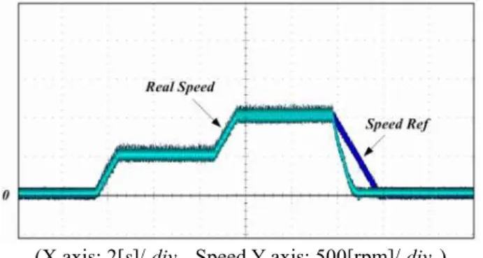
Fig. 18 shows the results of the acceleration control. In the modeling of the railway vehicle system, the speed was specified as 0→500→1000→0[rpm], and the actual speed was tracking accordingly. The reason why the actual speed became 0 faster than the speed command value when it is
Fig. 14. Hardware configuration of a fuel cell powered
railway vehicle uing a TIB converter
(X axis: 2[s ]/ div. , Voltage Y axis: 100[ V ]/ div. )
Fig. 15. DC-Link voltage control according to the input
voltage change of the vehicle
(X axis: 10[ sm ]/div , Voltage Y axis: 100[V]/ . .
div Current Y axis: 1[A]/div ) .
Fig. 16. TIB converter A phase current and output voltage
(X axis: 10[ sm ]/div , Output Voltage Y axis: 100[V]/. div , . Switch Voltage Y axis: 250[V]/div , Switch Current Y .
axis: 2.5[V]/ div ) .
Fig. 17. Hardware TIB converter output voltage and phase
controlled to 0 is because the programming is performed with the PWM off when the set value is 0 for the stability of the experiment.
Fig. 19 shows the efficiency analysis for each applied converter. The efficiency was measured by comparing the TIB converter with a conventional converter. The efficiency was analyzed at steady states of 300, 500, and 1000[rpm]. Under steady state, the average current of the TIB converter was 1.5[A], and the input current was approximately 3[A]. That equates to 10% of the total power. Fig. 20 shows that the efficiency of the conventional converter was 89.5~90.5%, and the efficiency of the TIB converter was 93.2~94.8%. The difference in efficiency from the simulation was 0.9% for general soft switching converters, and 2.1% for soft switching TIB converters, but the efficiency difference was higher in the TIB converter even though higher efficiency results were obtained. It can be seen that the difference in efficiency was a maximum of 4.8% at 500[rpm].
5. Conclusion
In this paper, A soft switching TIB converter for a fuel cell powered railway vehicle was proposed. The reduction
of switch current stress was confirmed during on-off transitions, and the reduction of input current ripple and current ripple in the inductor. Soft switching TIB converters are constructed with transformer type inductors, to control the input current ripple and the current ripple flowing through the inductor and switch. This suggests that the life of the system can be extended and that the reliability of the controller is better than that of the previous method.
For this, a TI ripple reduction mode was proposed and the mode operation was analyzed.
In addition, ZCS turn-on, which turns on when the current flowing through the switch is zero, was applied by utilizing a soft switching technique, and in addition the mode operation was analyzed. Ripple reduction mode and soft switching mode occur simultaneously in the control cycle, to reduce input current ripple and switch current stress. In addition, TI has a structure in which windings are on both sides of a single ferrite core, which has the advantage of having larger inductance than a normal inductor of the same physical dimensions. This is advantage in terms of stability control, and the weight of the system.
The results of this study are as follows:
1) The soft switching TIB converter showed up to 7.5% higher efficiency under low load conditions than a typical soft switching converter. Further, the inductor current ripple was reduced by up to 23% compared to a typical interleaved soft switching converter.
2) The current ripple reduction topology (using the magnetization inductance) functioned well, and the ZCS turn-on operation was well controlled.
3) The efficiency of the soft switching TIB converter was 4.8% higher than that of general soft switching converter.
In this paper, the scale-down fuel cell powered railway vehicle is used. So it is necessary to design using actual parameters in future research. However, it is considered that the controller and the circuit configuration can be used in the same way as the scale-down model in this paper. Therefore, this study will give a direction for it.
Acknowledgements
This research was supported by “Research on rail vehicle components interface and modularity guidelines plan” of the Korea National University of Transportation, Republic of Korea.
References
[1] N. G. Jung, J. M. Kim, “Contact Loss Simulator to Analyze the Contact Loss of a Rigid Catenary System,” JEET, Journal of Electrical Engineering & (X axis: 2[s]/ div , Speed Y axis: 500[rpm]/ . div ) .
Fig. 18. The acceleration control the results of fuel cell
powered railway vehicle
Technology, vol. 12, no. 3), pp. 1320-1326, 2017. [2] N. G. Jung, J. M. Kim, “Arc Detection System using
a Spectrometer for Status Monitoring of a Rigid Catenary,” JEET, Journal of Electrical Engineering & Technology, vol. 12, no. 6, pp. 2419-2425, 2017. [3] N. G. Jung, K. S. Lee, “The New Approach of the
Impedance Calculation Method of Fault Current Analysis in the AT Feeding Method of the Electric Railway,” JEET, Journal of Electrical Engineering & Technology, vol. 11, no. 5, pp. 1519-1525, 2016. [4] A.R. Miller et al., “System design of a large fuel cell
hybrid locomotive,” Journal of Power Sources, 173, pp. 935-942, 2007.
[5] J. P. Sim et al., “Principles and Applications of Hydrogen Fuel Cells for Renewable Energy,” The Korean Institute of Electrical Engineers, vol. 61, no. 11, pp. 15-22, 2012.
[6] Feng Hong, Yu Wu et al., “A Passive Lossless Soft-Switching Single Inductor Dual Buck Full-Bridge Inverter,” Journal of Power Electronics, vol. 18, no. 2, pp. 364-374, 2018.
[7] Li Jiang et al., “Optimized Operation of Dual-Active-Bridge DC-DC Converters in the Soft-Switching Area with Triple-Phase-Shift Control at Light Loads,” Journal of Power Electronics, vol. 18, no. 1, pp. 45-55, 2018.
No-Geon, Jung received the B.S
degree in rolling stocks electric engine-ering from the Korea National Railroad College in 2012, and received Ph.D. degree from Korea National University of Transportation in 2018. Since 2018, he has been with Korea Railroad Research Institute. His research interest is power electronics of railway.
Jae-Moon, Kim received the B.S
degree in 1994 and the Ph.D. degree in 2000 from Sungkyunkwan University. From 2004 to 2011, he was with the department of rolling stock electrical engineering, Korea National Railroad College. Since 2012, he has been with the department of transportation engineering in the transportation graduated school, KNUT. His research interests are power conversion in industry fields, traction and regeneration control in electric railway.