P2-99 / C. H. Kim
• IMID 2009 DIGEST
Abstract
We fabricated Dye-Sensitized Solar Cells(DSSCs) which are modified by using liquid crystals(LCs) and electro- deposition on cathode electrode in order to apply to flexible DSSCs. We deposited Pt metal layers on ITO electrode through the method of electro-deposition process during low-temperature. We could expect the long-term stability by using ionic liquid(IL) and liquid crystals(LCs). We can also see the enhancement of efficiency through orientation of LCs in gel-state electrolyte using liquid crystals at the DSSCs.
1. Introduction
Dye-sensitized solar cells (DSSC) have attractive features in terms of the high light-to-electricity conversion efficiency and the cost effectiveness [1]. Although the impressive light-to-electricity conversion efficiency has been obtained for photovoltaic cells with liquid electrolytes, the use of liquid electrolytes may result in some practical limitations of sealing, long-term operation and flexible applications. Therefore hole-conductor [2] and polymeric materials [3] have been attempted to substitute the liquid electrolytes for solid-state DSSCs, and then ionic liquids have been used to prepare non-volatile iodide electrolytes due to their favorable properties such as thermal stability, nonflammability, high ionic conductivity, negligible vapor pressure [4, 5]. In addition to flexible application, the solid-state or gel-state electrolyte should be used to prevent penetration of liquid and leak of electrolyte for flexible DSSC using polymer substrate. The flexible DSSC must be fabricated through low-temperature process because typical flexible plastic substrate cannot be maintained at temperature of up to 500℃ commonly used for sintering the TiO2 and Pt layers. Though some promising routes for low-temperature sintering TiO2 layers have been proposed, the conversion efficiency cannot compare with efficiency
obtained by the standard high-temperature process [6, 7]. Besides the low-temperature process of Pt layers is not considered. The counter electrode is usually prepared by spreading a drop of H2PtCl6 and 2-propanol solution on a conducting glass substrate, followed by its annealing at 450℃. The platinized counter electrode is also prepared by depositing Pt particles by sputtering. They also carried out annealing at 450℃ with the electrodeposited-platinum counter electrode showing enhanced performance [8].
In paper we consider the modification of two elements for flexible Dye-sensitized solar cells(DSSC). We modified cathode electrode as accompanying electro-deposition on ITO glass substrate to apply the low-temperature deposition of Pt layer to the counter electrode of DSSC. The second, we modified the electrolytes in order to maintain long-term stability and to make non-volatile electrolytes through the mixture of ionic liquid(IL) and liquid crystals(LCs) [5]. We also made gel-state electrolyte by low molecular mass organogelator (12-hydroxy- stearic acid) [9]. We can expect the enhancement of efficiency through the orientation of LCs by the photoelectric field (PEF)[5,10] and could see enhanced DSSC in gel-state electrolyte using liquid crystals in the comparison with ionic liquid(IL) electrolyte.
2. Experimental
We made the ITO electrode embed by Pt nanoparticles through electrodeposition that is low-temperature process (Fig. 1). The electrolyte of electrodeposition used 5mM Pt(II) salt solution. Pt(II) solution was made dissolving K2PtCl4 (II) (Aldrich) powder in deionized water. In Figure 1, the deposition of Pt layer on the ITO substrate(<19Ω) was carried out at a constant potential of DC 2V for elapsed times from 30 second to 3 minute. Transmittance of ITO
The modification of materials for flexible Dye-Sensitized
Solar Cells
Chang Ho Kim
1, In Young Han
2, and Jae-Hoon Kim
1,2*
1
Research Institute of Information Display, Hanyang University, Seoul, Korea TEL:82-2-2220-0343, e-mail: [email protected]
2
Dept. of Electronics and Computer Engineering, Hanyang University, Seoul, Korea
P2-99 / C. H. Kim
IMID 2009 DIGEST • glass embedded by Pt nanoparticles decreased to
about 60 % for elapsed time of 3 minute. Transmittance for elapsed time of 30 second is about 85%. Fig. 1 shows the size of Pt nanoparticles in AFM images. TiO2 photoanode was prepared as follows. Non-porous TiO2 was deposited on ITO glass from 5% Ti(IV) butoxide (97%, Aldrich) by spin coating, and then we annealed it at 450℃. The resistance of ITO glass increased to 40Ω due to annealing at 450℃. TiO2 paste (Ti-Nanoxide D/SP, Solaronix) was cast on this coated substrate by a doctor blade technique. The glass was sintered at 450℃ for 60min. The resulting TiO2 film was sensitized with 3E-4M N719 dye (Solaronix) for 24 h. We prepared two electrolytes and the first electrolyte consisted of 0.05M I2 (ACS Reagent, Aldrich), 0.1M LiI (99%, Aldrich), 0.6M 1,2-dimethyl-3-hexylimidazolium iodide (DMHII, Ionic liquid, 98%, C-TRI), and 0.5M 4-tert-butylpyridine (96%, Aldrich) in methoxypropionitrile (>98%, Fluka)(IL electrolyte). The second electrolyte (IL-LC electrolyte) consisted of IL electrolyte and 10% (w/w) liquid crystals (E7, Merck).
The gel-state electrolyte was prepared by adding 5 wt% 12-hydroxystearic acid (HSA) (99%, Aldrich) into liquid IL electrolyte and IL-LC electrolyte respectively, and then heated under stirring until the low molecular mass organogelator(12-hydroxystearic acid) melted. After cooling down to room temperature, the gel-state electrolyte was formed [9]. In the case of
IL-LC the gel-state was formed over adding 5 wt %
12-hydroxystearic acid. Maybe Liquid Crystals prevent forming gelation of organogelator by getting between 12-hydroxystearic acids.
Fig. 1. The AFM images of Pt nanoparticles deposited by electro-deposition process on ITO electrode (1atm, 40℃): (a) DC 2V, 30sec. and (b) DC 2V, 3min.
3. Results and discussion
The Pt counter electrode was made through electro-deposition under low-temperature process (<40℃, 1atm). The size and layer of Pt nanoparticles show in Fig. 1. The counter electrode depositing Pt for 30 sec. at DC2V had one layer surface and the height of Pt nanoparticle was below 25 nm (Fig. 1(a)). The deposited Pt counter electrode for 3min. had the height of 60 nm and transmittance decreased under 60%. Fig 1(b) shows that the Pt counter electrode depositing for 3 min. has multi-domain through AFM image. The formation of multi-domain would show the decrease of photocurrent because of the decrease of surface area of Pt and the increase of resistance of junction between Pt particles, which could be observed through the photocurrent density and efficiency in Fig. 2. We fabricated the DSSCs using counter electrode electrodepositing Pt and the photocurrent(I)-V curve of DSSCs was monitored during illumination of general light source(Pin). Photoconvesion efficiency was obtained from followed equation (1). oc sc in oc sc c in oc sc c in e V I P FF P FF V J A P FF V I A P P max max , 100 100 % 100 = × = × = × = Q η (1)
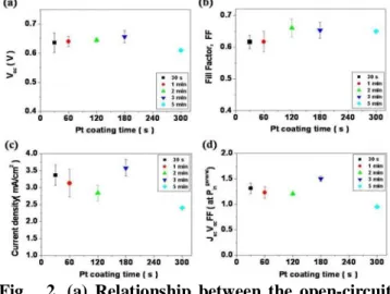
In Fig. 2 the DSSCs using counter electrode deposited Pt metal for short time of 30sec. effectively have good efficiency and the DSSCs for elapsed time of 3min. show the optimal photocurrent and efficiency in IL-LC electrolyte.
Fig. 2. (a) Relationship between the open-circuit
photocurrent(Voc) and Pt deposited time on ITO
glass in IL-LC electrolyte, (b) The fill factor(FF),
(c) current density, and (d) JscVocFF at general
P2-99 / C. H. Kim
• IMID 2009 DIGEST
Fig. 2(c) shows that the photocurrent density diminishes according as time coating Pt increase from 30 sec. to 2 minutes. We could observe the decrease of photocurrent in Fig. 2(c) because of the decrease of surface area of Pt and the increase of resistance of junction between Pt particles through forming multi-domain. But the DSSC depositing Pt for 3 min. was optimal photocurrent and efficiency. In Fig. 2(b) the Fill Factor was over 0.65 from 2 min. to 5 minutes. The Fill Factor correlates with Pt catalytic actions between Pt electrode and electrolyte at interface. Therefore the decrease of photocurrent as the decrease of surface area and the increase of resistance by multi-domain perhaps compete against the increase of Pt catalytic activity at interface. In case of DSSC coating Pt for 5min the Fill Factor had 0.65 which was optimal value, but the photocurrent density rapidly reduced to 2.40 mA/cm2 (TABLE 1). It is maybe the reason of the sudden increase of resistance by multi-domain.
The Photovoltaic parameters of DSSCs are shown in TABLE 1, which the DSSCs are fabricated through counter electrode of variable Pt deposition times.
TABLE 1. Photovoltaic mean parameters of the DSSCs fabricated through variable Pt coating times.
Pt coating
time Electrolyte Voc(V) Jsc (mA/cm2) FF ×(100/PJscVocinFF)*(%)
30 sec. IL 0.60 3.45 0.65 1.34×(100/Pin) 30 sec. IL-LC 0.64 3.37 0.62 1.33×(100/Pin) 30 sec. IL-LC+5%HSA 0.61 2.76 0.64 1.08×(100/Pin) 30 sec. IL+5%HSA 0.59 1.96 0.68 0.79×(100/Pin) 1 min. IL-LC 0.64 3.13 0.62 1.24×(100/Pin) 2 min. IL-LC 0.65 2.83 0.66 1.21×(100/Pin) 3 min. IL-LC 0.66 3.58 0.65 1.53×(100/Pin) 5 min. IL-LC 0.61 2.40 0.65 0.95×(100/Pin)
* I-V curves of DSSCs were measured as using general light source (Pin).
We modified the electrolytes in order to maintain long-term stability and to make non-volatile electrolytes through the mixture of ionic liquid(IL) and liquid crystals(LCs) [5]. The IL-LC(liquid crystal) electrolyte was more non-volatile electrolyte than the ionic liquid electrolyte(IL) because IL-LC electrolyte had more viscosity. However, the IL-LC electrolyte was not gel-state. TABLE 1 show that the efficiency of DSSCs using IL-LC electrolyte had similar value as that of DSSCs using IL electrolyte. The enhancement of efficiency through the orientation of LCs did not be observed in liquid electrolyte; on the contrary, the Fill Factor and efficiency were smaller.
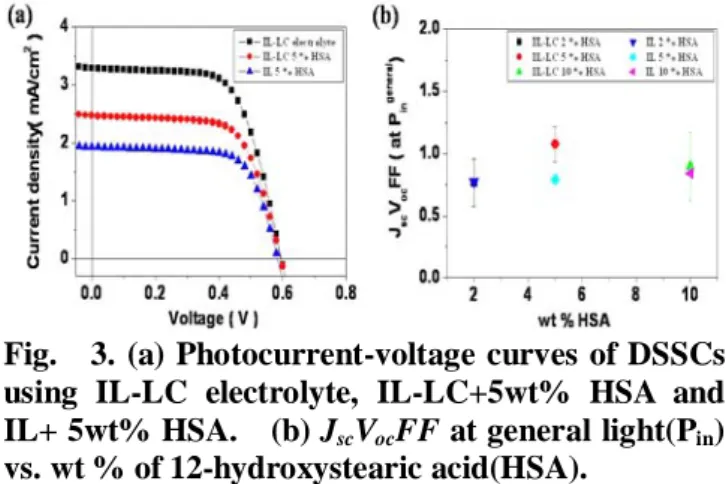
The DSSCs using gel-state electrolyte have the lower photocurrent density than that of IL-LC electrolyte (Fig. 3(a)). In case of IL-LC+5% HSA gel-state
electrolyte, the photocurrent density and efficiency had larger value than that of the DSSC injecting IL+5% HSA gel-state electrolyte (Fig. 3). The DSSC of IL-LC+5% HSA gel-state electrolyte was optimal and Fig. 3(b) show that the efficiencies of DSSCs using liquid crystals in gel-state enlarged in contrast to those of DSSCs filling IL-HSA gel-state electrolyte. The effect which is the transfer of hole in the HOMO level of the Ru-dye to the opposite counter electrode through the orientation of LCs by the photoelectric field (PEF)[10] probably increases in gel-state.
Fig. 3. (a) Photocurrent-voltage curves of DSSCs using IL-LC electrolyte, IL-LC+5wt% HSA and IL+ 5wt% HSA. (b) JscVocFF at general light(Pin) vs. wt % of 12-hydroxystearic acid(HSA).
4. Summary
We fabricated Dye-Sensitized Solar Cells(DSSCs) modified by using liquid crystals(LCs) in electrolyte and electrodepositing Pt nanoparticles on ITO glass for counter electrode in order to apply to flexible DSSCs. The deposition of Pt layer on ITO glass was carried out at constant potential of DC 2V for elapsed time. The Photocurrent density (Jsc) of DSSCs using counter electrode embedded by Pt nanoparticles for elapsed time of 30 sec. and 3 min. was 3.37 mA/cm2 and 3.58 mA/cm2 in IL-LC electrolyte, respectively (TABLE 1). We found that the DSSCs using counter electrode deposited Pt metal for short time of 30sec. effectively have good efficiency. We also made gel-state electrolyte by low molecular mass organogelator. We observed enhanced DSSC in gel-state electrolyte using liquid crystals in the comparison with ionic liquid(IL)+HSA electrolyte, which is probably the enhancement of efficiency through the orientation of LCs by the photoelectric field (PEF).
We measured I-V curve of DSSCs as using the general light source (Pin) and did not know the power of Pin. However, we are going to measure the photoconversion efficiency (ηe) under an irradiation of
P2-99 / C. H. Kim
IMID 2009 DIGEST • AM1.5 with optimal DSSCs and flexible DSSCs.
5. Acknowledgement
This research was supported by a grant (F0004052-2009-32) from Information Display R&D center, one of 21st Century Frontier R&D Program funded by the Ministry of Knowledge Economy of Korean government. We gratefully acknowledge to Jihun Kim in master’s degree from Hanyang University.
6. References
1. B. O’Regen and M. Grätzel, Nature, 353, 737 (1991).
2. U. Bach, D. Lupo, P. Comte, J. E. Moser, F. Weissortel, J. Salbeck, H. Spreitzer, and M. Grätzel, Nature, 395, 583 (1998).
3. F. Nogueira, J. R. Durrant, and M. A. De Paoli,
Adv. Mater., 13, 826 (2001).
4. P. Wang, S. M. Zakeeruddin, P. Comte, I. Exnar, and M. Grätzel, J. Am. Chem. Soc., 125, 1166 (2003).
5. N. Yamanaka, R. Kawano, W. Kubo, N. Masaki, T. Kitamura, Y. Wada, M. Watanabe, and S. Yanagida, J. Phys. Chem. B, 111, 4763 (2007). 6. M. Dürr, A.Schmid, M. Obermaier, S. Rosselli, A.
Yasuda, and G. Nelles, Nature materials, 4, 607 (2005).
7. H. Lindström, A. Holmberg, E. Magnusson, S-. E. Lindquist, L. Malmqvist, and A. Hagfeldt, Nano
Letters, 1[2], 97 (2001).
8. C. H. Yoon, R. Vittal, J. Lee, W-. S. Chae, and K-. J. Kim, Electrochimica Acta, 53, 2890 (2008) 9. Z. Hue, S. Dai, C. Zhang, F. Kong, X. Fang, L.
Guo, W. Liu, L. Hu, X. Pan, and K. Wang, J. Phys.
Chem. B, 112, 12927 (2008).
10. S-. J. Yoon, M. Joo, U-. J. Hwang, and N. Kim, J.