124
Copyright ⓒ The Korean Institute of Electrical Engineers
A High Efficiency LLC Resonant Converter-based Li-ion Battery
Charger with Adaptive Turn Ratio Variable Scheme
Yeong-Jun Choi*, Hyeong-Gu Han*, See-Young Choi*, Sang-Il Kim* and Rae-Young Kim
†Abstract
– This paper proposes an LLC resonant converter based battery charger which utilizes an adaptive turn ratio scheme to achieve a wide output voltage range and high efficiency. The high frequency transformer of the LLC converter of the proposed strategy has an adaptively changed turn ratio through the auxiliary control circuit. As a result, an optimized converter design with high magnetizing inductance is possible, while minimizing conduction and turn-off losses and providing a regulated voltage gain to properly charge the lithium ion battery. For a step-by-step explanation, operational principle and optimal design considerations of the proposed converter are illustrated in detail. Finally, the effectiveness of the proposed strategy is verified through various experimental results and efficiency analysis based on prototype 300W Li-ion battery charger and battery pack.Keywords:
LLC resonant converter, Battery charger, High efficiency, Adaptive turn ratio, Wide output voltage1. Introduction
Recently, various green transportations such as xEVs, E-bike, and E-scooter using batteries as a main power source, have expeditiously developed and penetrated the commercial marketplace. Generally, lithium-ion batteries are primarily used in such applications due to diverse reasons such as high energy densities, no memory effects and low self-discharge rates [1].
Meanwhile, the importance of the Li-ion battery charging system has also been increased to ensure safe and powerful use of the battery. Most charging systems employ a constant current-constant voltage (CC-CV) charging profile as displayed in Fig. 1 to prevent overcurrent and overcharge of the battery where the dashed line stands for a battery voltage Vbatt and the solid line stands for the battery
charging current Ibatt [2]. As can be seen from the figure,
the terminal voltage of the battery is widely varied from the cut-off voltage to the maximum charging voltage during the entire charging process; hence, Li-ion battery chargers should cover a wide output voltage range.
LLC resonant converter is a promising high-efficiency battery charger candidate possessing several advantages [3-5]. The converter inherently achieves zero voltage switching (ZVS) of the primary side switches and soft commutation capability of semiconductor devices over the whole operational range. Therefore, the turn-on loss is small and the reverse recovery loss of the diode is reduced, so that a high switching frequency operation is possible and the power density of the entire system can be increased.
Additionally the magnetic elements of the resonant tank can be integrated into a single transformer core, which is advantageous in terms of cost.
However, the LLC resonant converter also possesses a handicap as a battery charger: There is a trade-off in the design methodology to achieving high efficiency and meeting wide output voltage variations to cover wide variations in battery terminal voltage. To achieve a wide output voltage range, the LLC resonant converter need to operate at a frequency lower than the resonant frequency. However, such operation decreases efficiency due to the presence of a large circulating current. Moreover, a small magnetizing inductance of the resonant tank is usually required; therefore, efficiency became worse due to an excessive turn-off loss and magnetizing current. Hence, the optimal design of an LLC resonant is realized to be a delicate process [6].
To overcome this problem, several studies have been performed [7-15]. One solution is to develop a design method for resonant tanks to meet a given battery voltage and efficiency specification. [7-12]. However, these studies only reveal the inherent trade-off relationship limitation that cannot naturally be overcome. In the literature, a strategy of using auxiliary windings was proposed to realize a wide output voltage [13]. However, since this method was proposed for hold-up compensation, so there is no focus on maintaining the ZVS condition, and it is difficult to apply it to a battery charger. Some other researches discussed solutions for high power applications such as 3.3kW or 6.6kW [14, 15]. The main concept of these studies is to integrate the many advantages of two or more DC-DC converters with topology modification. However, it is impossible to apply results of these researches directly for low power applications below 500W. † Corresponding Author: Dept. of Electrical and Biomedical Engineering,
Hanyang University, Korea. ([email protected]) * Dept. of Electrical Engineering, Hanyang University, Korea.
({choi0jun, pehan09, si401}@hanyang.ac.kr, [email protected],) Received: February 16, 2017; Accepted: June 16, 2017
Fig. 1. CC-CV charging profile
This paper proposes a high efficiency 300W Li-ion battery charger based on LLC resonant converter that uses an adaptive winding ratio scheme to guarantee a wide output voltage range. The proposed converter adopts a half-bridge converter for the step-down capability on the primary side and a center tap rectifier for the low forward voltage drop on the secondary side. The adaptive winding ratio method, which is controlled via the auxiliary circuit, enables high efficiency to be achieved under widely varied output voltages. By adopting adaptive winding ratio method, the magnetization inductance of the resonance tank can be designed to a large value. Therefore, the conduction and the switching off losses at the primary side are decreased, which means the total efficiency is improved.
The rest of this paper is organized as follows. In Section II, the proposed converter and operating mode analysis are described. In Section III, a design example is presented for a “given condition”. In Section IV, experimental results which include waveforms and efficiency and analysis based on the results are presented to verify the effectiveness of the proposed method.
2. Proposed Battery Charger with an Adaptive
Turn Ratio
2.1 Circuit description
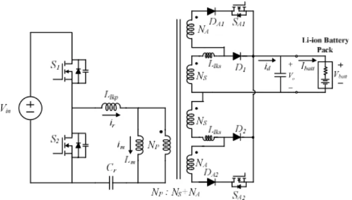
The proposed battery charger can is displayed in Fig. 2. The first stage of the proposed charger is the same as an conventional half-bridge LLC resonant converter where Vin
denotes the input voltage, S1, S2 denote the main switches,
Llkp and Llks denote the leakage inductance of the primary
side and the secondary side of the integrated transformer,
ir denotes the resonant current, Lm denotes the magnetizing
inductance, im denotes the magnetizing current and Cr is
the resonant capacitor. Np denotes the number of the primary winding of the transformer. The secondary structure of the proposed charger is similar to conventional center tap rectifier. On the basis of the conventional structure, the transformer winding structure of secondary side is modified by adding additional windings and its auxiliary driving circuit, where NS, NA denote the number
of turns with regard to the secondary and auxiliary
windings, SA1, SA2 denote the auxiliary switches, and D1,
D2, DA1, DA2 denote the rectifier and auxiliary diodes.
These modified structures allowed the turn ratio of the transformer to be varied adjustably. For example, if SA1
and SA2 are turned on, the effective number of secondary
winding is increased to the sum of NS and NA, that is
defined as “high gain mode” in this paper. When SA1, SA2
are turned off, the proposed charger operated with NS turns,
which is defined as “normal mode”. The id, Vo, Vbatt and ibatt
stand rectified current, output voltage, battery voltage and the battery charging current respectably. In this paper, Vo
and Vbatt are assumed to be the same.
2.2 Operational principle
Fig. 3 displays the output voltage or voltage gain curve of the LLC resonant converter with respect to the switching frequency. As can be seen from the graph, when the operating frequency is changed, the output voltage is adjusted accordingly. Supposing that the Li-ion battery possesses a terminal voltage range between 25V and 42V as seen in Fig. 3, the LLC resonant converter satisfies this voltage range to realize the CC-CV charging profile.
2 o in n V M V × = (1)
(
)
2 2 2 2 2 2 2 1 1 1 1 2 1 p o o p k k M k j Q k w w w w w w w w æ ö ç ÷ ç ÷ + è ø = æ ö + æ ö æ ö ×ç - ÷× +ç - ÷ ç ÷ ç ÷ + è ø è ø è ø (2) where, m lkp L k L = , r/ r o L C Q R = , o 1 r r L C w = , 1 p p r L C w = , p S N n N = , 2 2 8 o o batt V n R I p = , Lp =LM +Llkp, 2 || ( ) r lkp M lks L =L +L n LConsequently, the converter has to be designed to cover
o
V +
the wide output voltage range capabilities.
Referring to (1), the voltage gain, M should be increased in order to obtain a wide range output voltage. Eq. (1) is expressed in detail in (2) where k is the ratio between Lm
and Llkp, Q denotes the quality factor, wo and wp denote the resonant angular frequencies, n denotes the turn ratio,
Ro denotes the equivalent load resistance, Lp and Lr are the
equivalent inductance that the secondary winding is open circuited or short-circuited respectively. [5, 16]. As can be seen from (2), Designing a small Lm is a simple solution to
have a wide output voltage range. The smaller Lm becomes
the smaller k as well, and resultantly, M increases However, this solution leads a deterioration of the overall efficiency of the converter due to the increased conduction and switch turn-off losses.
Fig. 4 displays the output voltage or voltage gain curve of the proposed LLC resonant converter. The converter with the proposed adaptive winding ratio technique has two different voltage gain curves: one is normal mode operation (indicated by a solid line) and the other is high gain operation (indicated by a dashed line). Under normal mode, the converter is not designed to achieve wide output voltage range. As a result, a large Lm that minimizes
conduction losses and switch turn-off losses is used. On the other hand, when a high output voltage is necessary, high gain mode is operational. In this mode, the auxiliary switches SA1 and SA2 are turned on and the turn ratio of the
transformer n increased from Np/NS to Np/(NS+ NA).
1 1 2 o in V V M n = × × × (3)
Eq. (1) can be rearranged to generate (3). From (1) and (3), it is easily seen that a smaller n generates a higher voltage gain peak at the below resonant frequency, as displayed in Fig. 4; the required high output voltage is generated. On the other hand, a smaller M indicates that the switching frequency variation with regard to output voltage regulation during charging is decreased. Hence, the proposed scheme enables the battery charger to generate a higher voltage gain with a larger magnetizing inductance under a narrow switching frequency variation. Therefore, the RMS value of the resonant current, turn-off loss and circulating current period at the primary side are reduced.
2.3 Operating modes of the proposed LLC resonant converter
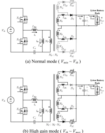
Fig. 5 displays the circuit diagram of two modes of operation of the proposed converter. When the threshold output voltage at which the operation mode is changed is expressed as Vth and the minimum and maximum output
voltages are denoted as Vmin and Vmax, respectively the
following analysis can be yield:
1) Normal mode [ Vmin < Vbatt < Vth ] : seen from Fig. 5(a),
SA1, SA2 are turned off and D1, D2 are forward biased.
Fig. 3. Voltage gain curve of the conventional LLC resonant converter
Fig. 4. Voltage gain curve of the proposed LLC resonant converter
o
V +
-(a) Normal mode ( Vmin ~ Vth )
o
V +
-(b) High gain mode ( Vth ~ Vmax )
Fig. 5. Configuration of the proposed converter according to operational mode
The current flows through D1 and D2 like the
conventional center-tap rectifier. The effective number of turns in the secondary side windings becomes NS; as a
result, the normal voltage gain is generated.
2) High gain mode [ Vth < Vbatt < Vmax ] : seen from Fig.
5(b), SA1, SA2 are turned on simultaneously and the
secondary side current does not continue to flow through the D1 and D2. The effective number of turns in the
secondary side windings becomes (NS + NA). As a result,
n is decreased to na; the turn ratio including auxiliary
windings shown in (4). Consequently, a high output voltage is obtained by applying a reduced turn ratio. The increased output voltage can be confirmed by substituting na for n in (3). p a S A N n N N = + (4)
2.4 Overshoot-less mode transition technique
If the auxiliary circuit on the secondary side is switched
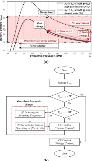
on during charging, an overshoot occurs in the primary side resonance current and the secondary side charging current. These transients cause stress and damage to the switch network or battery pack and require resolution. Therefore, this paper adopts an overshoot elimination algorithm depicted in Fig. 6(a). This algorithm temporarily increases the switching frequency first and then turns on the switch for the mode change to prevent overshooting as can be seen in Fig. 6(b).
3. Design Example
In order to explain the above sections briefly, a design example is presented based on Table 1. The electrical specifications of the converter in the design example are as follows: the nominal input voltage, Vin as 311V, the
cut-off voltage of the battery, Vbatt_min is 25V, the maximum
charging voltage is 42V, and k is 10 with margin consideration. The charging current is determined to be 7A; the output power is 300W and the turn ratio of the normal mode is 6.5 where the converter operates at a resonant frequency fo with a cut-off voltage of 25V.
3.1 Selection of turn ratio of transformer
The turn ratio of the transformer, n, needs to be suitably selected to maximize efficiency and provide DC gain appropriate from the maximum charging voltage to the cut-off voltage of the battery at the resonant frequency fo.
Considering the forward voltage drop of the secondary side diodes to be VF, n is given to (5) where the DC gain
at fo is given as Mw0 =(k+1) /k [5, 16]. Assuming VF =
0.5V and substituting the given electrical specifications into (5) yields n = 6.5. The maximum voltage gain, Mmax, is
required to be 1.8 times larger than Mwo in order to regulate
output voltage according to the given specifications. The quality factor Q is selected to be 0.25 in order to generate a high DC gain under normal mode.
0 _ min 2( ) p in s bat F N V n M N V V w = = × + (5) (a) (b)
Fig. 6. The overshoot elimination algorithm: (a) the switching frequency trajectory; (b) A flow chart
Table 1. Design parameters
Item (Designator) Conventional LLC converter [5]
Proposed LLC converter Resonant Frequency (fo) 130 kHz 130 kHz Transformer Turn Ratio
(NP:NS:NA) 46 : 7 46 : 7 : 2 Magnetizing Inductance (Lm) 350 uH 470 uH Resonant Inductor (Lr) 33 uH 33 uH Resonant Capacitor (Cr) 23 nF 23 nF Control Sampling Period 1 usec 1 usec
Mode Change Voltage
3.2 Magnetizing inductance and the threshold voltage selection
The magnetizing inductance Lm is selected in
consideration of the ZVS condition. To satisfy the ZVS condition, peak magnetizing inductor current, im,peak of (6)
should be able to discharge the parasitic output capacitance. This relationship can be expressed as (7) where Coss is the
parasitic output capacitance of the MOSFET, Ts is
switching period, tdead is dead time of the MOSFET. The
large Lm is preferred in order to achieve the minimum
conduction losses within the range satisfying (7) [17].
, 4 o s m peak m nV T i L = (6) 16 s dead m oss T t L C × £ × (7)
However, an increase in Lm leads to an increase in k in
(1), which leads to a decrease in the peak voltage gain. Hence, as shown in Fig. 7, under the range satisfying (4), the Lm is designed to be possible to generating the Mode
Change Voltage Vth within the operating frequency of the
converter (78 kHz~130 kHz). Vth is designed to be a median
value of 33 V in consideration of the maximum charging voltage of the battery pack and the cut-off voltage.
(a)
(b)
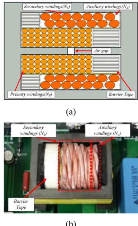
Fig. 9. An integrated transformer of the resonant tank: (a) winding structures and (b) a manufactured prototype
3.3 Determining the number of auxiliary windings
The number of the auxiliary winding turns, NA, is
optimized through the voltage gain curve as displayed in Fig. 8. By increasing NA, M is increased due to the effect
of the decreased na that is confirmed by substituting na for
n in Eq. (2). The increased NA and decreased na also affect
the current flowing in the primary side; im,peak, RMS values
of magnetizing current im,rms and resonant current ir,rms as
can be seen in (8), (9) and (10) [17]. As can be seen from these relationships, each value is proportional to the turn ratio of the transformer. Therefore, by applying the reduced
na, im,peak@na,im,rms@na, ir,rms@na which are applied value of
na, becomes smaller than im,peak@n,im,rms@n, ir,rms@n which are
applied value of n and it leads an efficiency improvement. In this paper, the NA is selected to generate the same
output voltage as Vth around the resonant frequency fo
(point 1), under consideration of satisfying a maximum charging , @ , @ 4 a 4 o s a o s m peak n m peak n m m nV T n V T i i L L = > = (8) , @ , @ 1 1 4 4 3 a 3 o s a o s m rms n m rms n m m nV T n V T i i L L æ ö æ ö = ç ÷> = ç ÷ è ø è ø (9) 4 2 2 2 , @ 2 4 2 2 2 , @ 2 2 1 8 8 2 1 8 8 a o o s r rms n o m o a o s r rms n a o m V n R T i nR L V n R T i n R L p p = + > = + (10) Fig. 7. Optimal magnetizing inductance (Lm) selection.
Fig. 8. Optimal number of turns of auxiliary winding selection
Fig. 10. Experimental setup of the prototype voltage of 42V (point 2). In this example, with regard to selecting the optimal high gain mode case, choosing this mode satisfies the maximum voltage gain as well as the smallest increase in the number of secondary windings. As a result, NA is selected to be 2 turns as seen in Fig. 7.
Figs. 9 (a) and (b) display the structure and design results of the integrated transformer using the EER 3542 magnetic core. As displayed in the Fig. 8(a), the number of the primary windings, NP, secondary windings, NS, and
auxiliary windings, NA are selected as 46, 7, and 2,
respectively.
4. Performance Verification
In order to verify the effectiveness of the proposed converter, experiments based on the experimental set seen in Fig. 10 are performed based on the detailed parameters listed in Table 1. In the experiment, Cortex M-3 is used for digital control, and for the LLC resonant converter implementation, FSFR2100 and STPS20M100S are used. Figs. 11(a) and (b) display the steady-state waveforms of the conventional LLC resonant converter battery charger under 10% and 80% load conditions, respectively where
Vds1 represents the drain source voltage of the S1 and ids1
represents the current flowing to S1.
Figs. 12 (a) and (b) display the same waveforms for the proposed LLC resonant converter battery charger. As can be seen from the waveforms, the peak value of magnetization current is decreased from 1.28A to 0.77A under heavy condition; the turn-off current is decreased from 2A to 1.8A under light load conditions and from 1.1A to 0.8A under heavy load conditions. The measured resonant current RMS value is decreased from 1.55A to 1.48A under a light load and is decreased from 1.95A to 1.91A under a heavy load. Additionally, the circulating current period is also decreased from 7.77μs to 7.09μs and decreased from 6.84μs to 4.91 μs under light and heavy load condition respectively.
The reason for this numerical reduction can be attributed to a large Lm due to application of the proposed LLC
resonant converter. Reduction of these factors reduces conduction and switching losses, leading to an improved
efficiency shown in Fig. 13.
From the efficiency comparison result between the conventional LLC resonant converter and the proposed
Turn-off current=2A Vds1 [200V/div] ids1 [2A/div] ir [2A/div] ZVS turn-on 5usec/div (a) IM_peak=1.28A Turn-off current=1.1A Vds1 [200V/div] ids1 [2A/div] ir [2A/div] ZVS turn-on 5usec/div (b)
Fig. 11. Experimental result of the conventional LLC resonant converter: (a) at 10% load and (b) 80% load Turn-off current=1.8A Vds1 [200V/div] ids1 [2A/div] ir [2A/div] ZVS turn-on 5usec/div (a) im,peak=0.77A Turn-off current=0.8A Vds1 [200V/div] ids1 [2A/div] ir [2A/div] ZVS turn-on 5usec/div (b)
Fig. 12. Experimental result of the proposed LLC resonant converter: (a) at 10% load and (b) 80% load
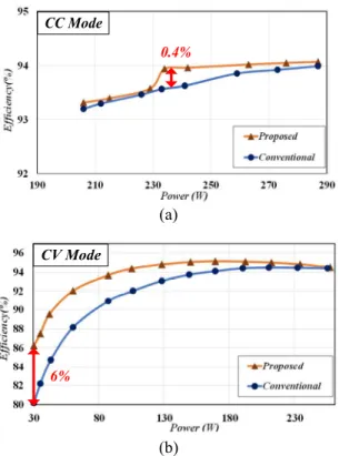
LLC resonant converter, the proposed one is superior to the conventional one over the entire operating range. The maximum efficiency of the CC charging process is 94.1%, which is 0.1% to 0.4% higher than that of the conventional one. The maximum efficiency of the CV charging process is 94.5%, which is 0.1% ~ 6% higher than the conventional one.
Fig. 14 displays the experimental waveform of CC-CV charging by applying the proposed converter. As can be seen from the figure, the CC-CV charging profile is appropriately implemented without any failures or unstable / unusable operation, despite the fact that a mode change occurred where the current reference of CCmode, Iref is 7A,
the voltage reference of the CV mode, Vref is 42V, the
initial voltage of battery pack Vinitial is 26V, Vfreq is a
voltage value output by DAC converter to show the tendency of the switching frequency variation.
Fig. 15 displays waveforms related to when the over-shoot elimination algorithm is and is not applied. As can be seen from the waveforms, when the overshoot elimination algorithm is not used, overshooting occurs in the resonance and output current. On the other hand, when the overshoot elimination algorithm is applied, mode conversion occurs without overshooting in either waveform. Therefore, it would be said that both the proposed converter with the adaptive turn ratio scheme operates well.
5. Conclusion
This paper proposes a high efficiency LLC resonant converter with a wide output voltage range using an adaptive turn ratio scheme for a 300W low power Li-ion battery charger. For a sequential description of the proposed method, this paper illustrates the operating principles and optimal design considerations of the proposed converter with topology analysis in detail. Finally, to verify the effectiveness of the proposed LLC resonant converter-based battery charger, experiments were conducted. Experimental results show that the proposed method operates reliably over a wide range of output voltages and achieves up to 6% more efficiently than conventional converter.
CC Mode 0.4% (a) 6% CV Mode (b)
Fig. 13. Efficiency comparison result between the conven-tional LLC resonant converter and the proposed one: (a) CC mode and (b) CV mode
Fig. 14. Experiment waveforms during the CC-CV charging process Iout [5A/div] ir [2A/div] Vbatt [5V/div] 100msec/div 12A 4A Mode change overshoot (a) Iout [5A/div] ir [2A/div]
Vbatt [5V/div] 100msec/div
Overshoot-less Mode Change
(b)
Fig. 15. Experiment waveforms under mode conversion: (a) without the overshoot-less algorithm and (b) with the overshoot-less algorithm
Acknowledgements
This work was supported by the Korea Institute of Energy Technology Evaluation and Planning (KETEP) and the Ministry of Trade, Industry & Energy (MOTIE) of the Republic of Korea (No. 20164010200860, No. 20168530050030).
References
[1] Yi-Hwa Liu, Jen-Hao Teng and Yu-Chung Lin, “Search for an optimal rapid charging pattern for lithium-ion batteries using ant colony system algori-thm,” in Industrial Electronics, IEEE Transactions on, vol. 52, no. 5, pp. 1328-1336, Oct. 2005
[2] A. A.-H. Hussein and I. Batarseh, “A review of charging algorithms for nickel and lithium battery chargers,” IEEE Trans. Veh. Technol., vol. 60, no. 3, pp. 830-838, Mar. 2011.
[3] Yang, B., Lee, F.C., Zhang, A.J. and Guisong Huang, “LLC resonant converter for front end DC/DC con-version,” in Proceedings of IEEE APEC, pp. 1108-1112, Aug. 2002.
[4] B. Yang, “Topology investigation for front end DC/DC power conversion for distributed power system,” Virginia Polytechnic Inst. State Univ., Ph.D.
dissertation, 2003.
[5] H. Choi, “Analysis and Design of LLC Resonant Converter with Integrated Transformer,” in
Pro-ceedings of IEEE APEC, pp.1630-1635, May 2007
[6] B. Lu, W. Liu, Y. Liang, F. C. Lee, and J. D. van Wyk, “Optimal design methodology for LLC resonant converter,” in Proceedings of IEEE APEC, pp. 533-538., Mar. 2006
[7] R. Beiranvand, B. Rashidian, M. R. Zolghadri, and S. M. H. Alavi, “Optimizing the Normalized Dead-Time and Maximum Switching Frequency of a Wide-Adjustable-Range LLC Resonant Converter,” IEEE
Trans. Power Electronics, vol. 26, pp. 462-472, Aug.
2011.
[8] R. Beiranvand, B. Rashidian, M. R. Zolghadri, and S. M. H. Alavi, “A Design Procedure for Optimizing the LLC Resonant Converter as a Wide Output Range Voltage Source,” IEEE Trans. Power Electronics, vol. 27, pp. 3749-3763, Feb. 2012.
[9] F. Musavi, M. Craciun, D. S. Gautam, W. Eberle, and W. G. Dunford, “An LLC Resonant DC/DC Converter for Wide Output Voltage Range Battery Charging Applications,” IEEE Trans. Power Electronics, vol. 28, pp. 5437-5445, Mar. 2013.
[10] H. Wang, S. Dusmez, and A. Khaligh, “Design and Analysis of a Full-Bridge LLC-Based PEV Charger Optimized for Wide Battery Voltage Range,” IEEE
Trans. Vehicular Technology, vol. 63, pp. 1603-1613,
Nov. 2014.
[11] Z. Fang, T. Cai, S. Duan, and C. Chen, “Optimal Design Methodology for LLC Resonant Converter in Battery Charging Applications Based on Time-Weighted Average Efficiency,” IEEE Trans. Power
Electronics, vol. 30, pp. 5469-5483, Dec. 2015.
[12] K. H. Park, Y. J. Choi, S. Y. Choi, and R. Y. Kim, “Design consideration of CC-CV controller of LLC resonant converter for Li-ion battery charger,” in
Proceedings of IEEE IFEEC, pp. 1-6, Nov. 2015.
[13] M. Y. Kim, B. C. Kim, K. B. Park and G. W. Moon, “LLC series resonant converter with auxiliary hold-up time compensation circuit,” in Proceedings of
IEEE ECCE Asia (ICPE & ECCE), pp. 628-633, Jul.
2011
[14] I. O. Lee, “Hybrid PWM-Resonant Converter for Electric Vehicle On-Board Battery Chargers,” IEEE
Trans. Power Electronics, vol. 31, pp. 3639-3649, Jul.
2016.
[15] J. S. Lai, H. Miwa, W. H. Lai, N. H. Tseng, C. S. Lee, C. H. Lin and Y. W. Shih, “A high-efficiency on-board charger utilizing a hybrid LLC and phase-shift DC-DC converter,” in Proceedings of IEEE IGBSG, pp. 1-8, 2014.
[16] H. Choi, “Design consideration of half-bridge LLC resonant converter,” Journal of Power Electronics, vol. 1, no. 1, pp. 13-20, Jun. 2007.
[17] Ya Liu, “High Efficiency Optimization of LLC Resonant Converter for Wide Load Range,” Virginia
Polytechnic Inst. State Univ., Master. dissertation,
2007.
Yeong-Jun Choi He received B.S degree in electrical and control engin-eering from Hanyang University, Seoul, Korea, in 2013, where he is currently working toward the direct Ph.D. degree. His current research interests include resonant converter, power factor correction converter and battery cell balancing circuit.
Hyeong-Gu Han He received B.S degree in Department of Control and Instrumentation Engineering from Korea National University of Transportation, in 2015 and the M.S. from electrical engineering from Hanyang University, Seoul, Korea, in 2017. Since 2017, He has been an engineer at LG electronics CTO division. His current research interests are resonant converter and battery charger.
See-Young Choi He received the B.S. and M.S. degrees in electrical engin-eering from Hanyang University, Seoul, Korea, in 1999 and 2001, respectively, where he is currently working toward the Ph.D. degree. From 2001 to 2006, he was a Senior Researcher at Hyosung Heavy Industry R&D Center, Seoul. From 2006 to 2014, he was a Senior Researcher at Samsung electronics. His current research interests are renewable energy, micro grid and resonant converter.
Sang-Il Kim He was born in Korea in 1975. He received the B.S., M.S. and the Ph.D degrees in electrical engin-eering from Hanyang University, Korea, in 1998, 2000 and 2017 respectively. From 2000 to 2005, he was a Re-searcher with POSCON Company, Korea. From 2005 to 2008, he was a member of the research staff at Samsung Advanced Institute of Technology, Yongin, Korea. Since 2008, he has been a Chief Research Engineer at Doosan Robotics Company, Seoul, Korea. His current research interests are power electronics control of electric machines, sensorless drives, electric/hybrid vehicle, and power conversion circuits.
Rae-Young Kim He received the B.S. and M.S. degrees from Hanyang Uni-versity, Seoul, Korea, in 1997 and 1999, respectively, and the Ph.D. degree from Virginia Polytechnic Institute and State University, Blacksburg, VA, USA, in 2009, all in electrical engineering. From 1999 to 2004, he was a Senior Researcher at the Hyosung Heavy Industry R&D Center, Seoul, Korea. In 2009, he was a Postdoctoral Researcher at National Semiconductor Corporation, Santa Clara, CA, USA, involved in a smart home energy management system. In 2016, he was a Visiting Scholar with the Center for Power Electronics Systems (CPES), Virginia Polytechnic Institute and State University, Blacksburg. Since 2010, he has been with Hanyang University, where he is currently an Assistant Professor in the Department of Electrical and Biomedical Engineering. His research interests include modeling and control of distributed power converter systems, soft-switching techniques, energy management systems in microgrid applications, modular power converter for renewable energies and motor drive systems. Dr. Kim was a recipient of the 2007 First Prize Paper Award from the IEEE IAS.