See discussions, stats, and author profiles for this publication at: https://www.researchgate.net/publication/228820527
Telediagnosis system for orthopedic deformity analysis based on 3D medical
imaging
Article in Proceedings of SPIE - The International Society for Optical Engineering · April 2000 DOI: 10.1117/12.383056 CITATIONS 0 READS 56 3 authors, including:
Some of the authors of this publication are also working on these related projects:
Bio-Image Informatics for Precision MedicineView project Myoung Hee Kim
Ewha Womans University
118PUBLICATIONS 773CITATIONS
SEE PROFILE
Helen Hong
Seoul Women's University
85PUBLICATIONS 279CITATIONS
SEE PROFILE
All content following this page was uploaded by Helen Hong on 20 May 2014. The user has requested enhancement of the downloaded file.
Telediagnosis System for Orthopedic Deformity Analysis
Based on 3D Medical Imaging
✝Myoung-Hee Kim, Helen Hong*, and Min-A Kim
Dept. of Computer Science & Engineering, Ewha Womans University,
11-1 Daehyun-dong, Seodamun-gu, Seoul, Korea 120-750
ABSTRACT
Due to the structural complexity of the bone, it is difficult to diagnose and make a treatment plan for injuries and diseases in bones. In this paper, we designed and implemented a telediagnosis system for orthopedic deformity analysis based on 3D medical imaging. In order to define the interosseous relationships in each bone and to evaluate a deformity without invasions, the system produces volumetric images by reconstructing the planar images spatially and provides deformity analysis by measuring distance, area, volume and angle among the bones. The reconstructed volumetric images are freely manipulated to simulate surgical operations such as translation, scaling, rotation and so on. Our system integrates three main components: server, clients and communication subsystem. It is also composed of three main functions including the information control manager for event and message process used between client and server, and surgical simulation manager for object visualization and manipulation in individual bones, and the medical database manager for patient information. The system also supports user-friendly graphical user interface and simultaneous use by multiple users.
Keywords:telemedicine, diagnosis, orthopedic surgery, surface modeling, surface rendering
1. INTRODUCTION
Due to the structural complexity of the bone, it is difficult to diagnose and make a treatment plan for injuries and diseases in bones. While ordinary planar images are customarily used to visualize abnormalities, these two-dimensional projections of bone densities are inadequate to describe the actual shapes and relative positions of bones. For this reason, there has been effort to use three-dimensional information derived from radiological images to generate a useful description of foot joint geometry.
✝
This work is supported by a grant No. HMP-97-I-2-0002 from Ministry of Health and Welfare in Korea.
*Correspondence: Helen Hong: Telephone: +82-2-3277-4408; Fax: +82-2-3277-4409; Email: [email protected],
Other author information: Myoung-Hee Kim: Telephone: +82-2-3277-2315; Fax: +82-2-3277-2306; Email:
The previously reported methods show that spatial reconstruction can be made from tomographic images and geometric measurements made from them. However, these methods require considerable manual interaction and are difficult and tedious. Furthermore, there is no clear consensus on the geometric features of the bone whose measurement will assist the physician in the most meaningful way.
In this paper, we designed and implemented a telediagnosis system for orthopedic deformity analysis based on 3D medical imaging. We focalized here on clubfoot. In order to define the interossous relationships in each foot bone and to evaluate a deformity without invasions, this system produces volumetric images by reconstructing the planar images spatially. It also helps to analyze the foot deformities as well as performs the surgical simulation by providing several manipulations such as translation, rotation, scaling, coloring, and so on.
In the remainder of this paper, we discuss related works about orthopedic deformity in Section 2, system description in Section 3 and conclusions in Section 4.
2. ORTHOPEDIC DEFORMITY : CLUBFOOT
Among the various kinds of foot deformities, clubfoot has been one of the major orthopedic problems in children. It is the
most common congenital disorder of the lower extremity and there are several variations1. Calcaneovalgus is the most
common type of foot deformity. This causes the foot to be sharply angled at the heel, with the foot pointing up and outward. In many cases, the top of the foot can touch the shin bone. Metartarsus adductus is another mild foot deformity where the front part of the foot is turned inward. Although present at birth, this foot deformity may not be diagnosed until the baby is a month to a few months old. This condition causes the child to walk with a toe-in-gait. Figure 1 shows a clubfoot inwardly rotated and turned on its side towards the other foot.
(a) Left clubfoot (b) The rear view of clubfoot Figure 1. Clubfoot
It is essential to have an accurate method for evaluating the severity of a clubfoot preoperatively. It is very difficult to detect this during infancy. There have been postmortem dissections and some studies to describe the interossous relationships and the gross morphology of individual bones in newborn clubfoot. Postmortem dissections disturb the interossous relationships because the ligamentous structures are disrupted. This has limitations in defining cartilaginous surfaces of immature bones on a clubfoot. Therefore, cryomicrotome sections and MRI have been used to demonstrate the cartilaginous and osseous structures in the infant foot and to assess the osseous relationships in foot deformities. It is difficult to understand a volumetric structure with radiological images and provide the actual shape and relative positions of the bones. For this reason, there have been efforts to use a three-dimensional model constructed with plastic bones of the foot and elastic strings simulating the ligaments. This is not adquate to provide knowledge of kinematics and pathological anatomy of the deformity2.
The spatial reconstruction for a clubfoot has been developed over several years. Herzenberg et al. described a method for developing a three-dimensional foot model from using CT and quantified the interosseous relationships in the feet of older children aged 3-10 years3. Charles E. Johnston et al. described a three-dimensional analysis of clubfoot deformity for the
bony pathoanatomy of clubfoot4. This allows visualization of the deformities which normally cannot be analyzed on plain
radiographs, and also shows that variety of interosseous relationships make up the clinical entity known as clubfoot. M.A.Rodrigues described the categorization of foot deformities5. Classification of the clubfoot is a longstanding problem documented in the medical literature. There is a general consensus among surgeons that a more objective method of assessment is required.
Our system has several advantages over the conventional computer supported medical diagnosis system for clubfoot. First, it supports the several kinds of functions of image processing and manipulation during diagnosis. The conventional system usually only provide tomographic images or the ability to process and visualize these images. However, our system provides not only planar image processing but also volumetric image processing and manipulation. Second, users with low-cost general-purpose computers can use our system through networks. The server contains almost all the information and complicated functions and each client only uses functions provided on the server.
3. SYSTEM DESCRIPTION
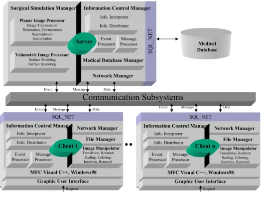
We define a client-server architecture that is shown in Figure 2. The resulting system has three main components: server, clients, and communication subsystems. The server supports information control manager, medical database manager, as well as providing both planar image processor and volumetric image processor. The clients support user interaction with the server and on-screen presentation of images and data. They provide a graphical user interface, information control manager in addition to transparently interacting with the server. The communication subsystem rely on local-area and broadband
networks used as communication links employing Transmission Control Protocol/Internet Protocol (TCP/IP) for transport and internetworking services.
Medical Database Manager
Communication Subsystems
Event Message Data Event Message Data
SQ L _N E T Network Manager Information Control Manager
Info. Interpreter Info. Distributor Message Processor Event Processor Surgical Simulation Manager
Planar Image Processor
Image Transmission Restoration, Enhancement
Segmentation Interpolation
Server
Event Message Data
Volumetric Image Processor
Surface Modeling Surface Rendering Medical Database SQL_NET MFC Visual C++, Windows98 Info. Interpreter Info. Distributor
Graphic User Interface
Network Manager File Manager Information Control Manager
Message Processor Event Processor Request Image Manipulator Translation, Rotation Scaling, Coloring, Insertion, Removal Client 1 SQL_NET MFC Visual C++, Windows98 Info. Interpreter Info. Distributor
Graphic User Interface
Network Manager File Manager Information Control Manager
Message Processor Event Processor Request Image Manipulator Translation, Rotation Scaling, Coloring, Insertion, Removal Client n
Figure 2. System architecture
The client-server interaction is mostly executed from the users on the client side. A graphical user interface in the client is implemented as a process interaction with the process running on a server. The user interface is in a set of process running in a MFC Visual C++ environment.
3.1 Information Control Manager
For our system, which deals with radiological and environmental information, we considered three types of information: structured data, text, and images6. Structured data are related to access control and network services. It also describes some other specific features. For instance, radiological images may have attribute such as the patient’s age, sex, examination date as well as anatomic, diagnostic, and semiological codes. Other data concern image characteristics, such as the number of row and columns, pixel sizes, bits per pixel, lookup table, image name, and acquisition equipment. Text includes notes and comments on the images. Images interest us not only as signle objects but they are frequently grouped into sets based on the specific criteria. In radiology, a sequence of images may make up the examination record, computerized axial tomography, or magnetic resonance. Several examinations belonging to the same patient from a clinical case or images may be grouped by anatomy and pathology. Images are not only two-dimensional radiological images but also three-dimensional
reconstructed images.
The information control manager consists of the information interpreter, the information distributor, the event processor, and the message processor. The information control manager exists on the server and on the clients and processes several requests, events, and messages. It allows users to request a request commands. The event is the command controls and communicates with the server and the message is the data for image and patient information. Our system starts after receiving the initial request that clients send to the server. Clients can use radiological images that are on the client or on the server, we select the upload or download icon for image transmission which can be used in a reciprocal manner.
The information interpreter checks incomming information and distinguishes it. If the information has no error, the information distributor sends it to the event processor receives from the information distributor and then transfer the event to the server through the network manager. The message processor also processes like the event processor.
3.2 Surgical Simulation Manager
The surgical simulation manager consists of the planar image processor, the volumetric image processor, and the image manipulator. Users can access the planar image processor, the volumetric image processor only by a request to the server. In case of image manipulator, users can easily access by a request to the client for interactivity. An overview of image visualization pipeline is shown in Figure 3. After the acquisition of a series of tomographic images of a patient, the data usually undergoes some processing for data conversion and possibly image filtering.
Medical Image Acquisition
Sampled 2D slices
Planar Image Processor
Image Transmission Image Transmission Image Restoration Image Restoration Segmentation Segmentation Image Enhancement Image Enhancement Interpolation Interpolation
Volumetric Image Processor
Reconstructed 3D image Image Manipulator Surface Modeling Surface Modeling Surface Rendering Surface Rendering
Figure 3. Image Visualization Pipeline [ The Planar Image Processor ]
The planar image processor contains the image transmission module, image restoration module, the image enhancement module, the image segmentation module, and the image interpolation module.
The acquisition of image data has a decisive influence on the success of further processing. The acquisition of digital image data, the computer-assisted process of operation planning and its subsequent intraoperative application usually occurs spatially separate locations7. The use of a teleradiology system has been proven to be effective in accessing digital image data. With the teleradiology, it is possible to receive digital images from the imaging modalities and to transmit them over ISDN lines or other computer networks. A multilevel data protection concept guarentees the security of the transmission. Above works is proceeded in the image transmission module.
The image restoration module reconstructs or recovers an image that has been degraded by using some prior knowledge of
the degradation phenomenon8. This includes a lot of filtering techniques, such as moving average filter, median filter,
multistage median filter, maximum filter, minimum filter, and adaptive MMSE filter. The principal objective of enhancement techniques from the image enhancement module is to process an image so that the resulting image is more suitable than the original image for a specific application. This includes histogram equalization, image halftoning, dithering, and so on.
The gray-level volumes usually represent a large number of different structures obscuring each other. To display a particular one, we have to decide which parts of the data we want to use or ignore. The segmentation module is needed to do this process and allows users to use thresholding, region growing, edge detection, and so on.
Acquisition of serial cross-sectional slice images has become ubiquitous in medical imaging. Because intra-slice spacing is typically greater than inter-slice spacing, image interpolation techniques often are used to fill in the intra-slice spaces and produce a uniformly dense image volume. The interpolation module consists of linear interpolation, shape-based interpolation, and kriging interpolation. Slice interpolation is used to decrease the intra-slice spacing by creating new slices in between existing ones. The most widely used slice interpolation technique is linear interpolation. Shape-based interpolation uses the contrast at the boundaries between different materials to perform interpolation9. This method begins by identifying a structure of interest in each slice of data by using a segmentation operator. Kriging interpolation was
introduced as a new interpolation method to the medical image community by Stytz10. It uses a weighted linear sum of
known data values to estimate the value of an unknown point. There are two broad classes of kriging: ordinary kriging and universal kriging.
[ The Volumetric Image Processor ]
A good understanding of 3D anatomical structure is important for diagnosis in order to comprehend complex anatomical structures and their relationships. The surface modeling technique is to extract an intermediate surface description of the relevant objects from the volume data. Only this information is then used for rendering. A clear advantage of surface-based methods is the possibly very high data reduction from volume to surface representations. The volumetric image processor contains surface modeling and rendering.
The surface modeling method extracts intermediate surface description of the relevant objects from the original 3D data to derive inter-slice connectivity, surface location, and surface gradient9. Triangles are used as surface elements and the algorithms basically consider a cube. Depending on whether one or more of these voxels are inside the object, a surface representation of up to four triangles is placed within the cube. The exact location of the triangle is founded by linear interpolation of the intensities at the voxel vertices. The result is highly detailed surface representation with subvoxel resolution. Surface orientations are calculated from gray level gradients.
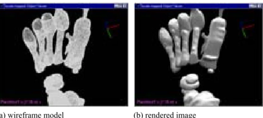
The surface rendering module supports the realistic display of an object, based on the position and characterisitics of its surface and the light sources illuminating it. The reflective properties of a surface are described with an illumination model such as the Phong model, which uses a combination of ambient light, diffuse and specular reflections. Our algorithm calculates the surface normal vectors from the gray level gradients in the data volume. Alternatively, the surface normal vectors of the triangles can be used directly. Figure 4 shows the results of surface modeling and surface rendering.
(a) wireframe model (b) rendered image
Figure 4. Results of surface modeling and surface rendering
A step further is to manipulate the data at the computer screen for surgical simulation. These techniques are especially usefule for orthopedic surgery where a foot is angled at the other position, and then rearranged to achieve a desirable shape. The image manipulator is used to manipulate the data for more accurate diagnosis. We provide several manipulations for surgical simulation, such as translation, rotation, scaling, coloring and so on. Thus our system allows users to interactively rearrange to achieve a desirable shape and direction. Several image manipulations are shown in Figure 5. Our system support both mono-object manipulation and multi-object manipulation. Figure 5 (a), (d) show the results of mono-object manipulation. Figure 5 (b),(c),(e),(f) show the results of multi-object manipulation. The color of individual bones are defined by a surgeon of Dept. of Orthopedic Surgery.
(a) mono-object rendering (b) multi-object coloring (c) multi-object scaling
(d) mono-object rotation (e) multi-object rotation (f) multi-object translation Figure 5. Image manipulation
3.3 User interface
Three sets of feet were included for experimentation. The two sets of feet were obtained from infants with MRI who had a left clubfoot and a normal appearing right foot. The third set of feet was a normal foot obtained from a twenty-six old womans with MRI. The MRI images were obtained with Siemens magnetom 63sp-4000 1.5T.
Our system was developed as a client-server architecture under two different environments. We implemented the server using C language on a Sun Ultrasparc workstation based on Unix. The client was run in commonly avaliable P.C. in Windows 98 and implemented in Visual C++. All user interface are run in a MFC Visual C++ environments. The networks
service was implemented on the top of TCP/IP using standard 4.3 BDS sockets.
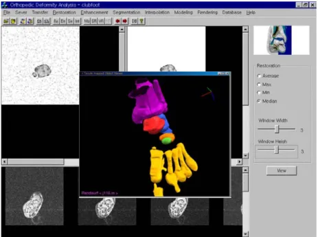
We present an example here to illustrate the system’s behavior. In order to permit the usage of our system, the user inputs a username and a password through the initial screen. If the user connects to the server successfully, they can download or upload several information to/from the server. Figure 6 shows the integrated user interface. Our user interface consists of three windows. It displays an original image on the left side and a processed image on the right side. On the bottom of the interface, there is one window for displaying series of medical image slices. The results of surface modeling and surface rendering are displayed in pop-up window. The various menus are placed on the top and right side of the interface. They also have several command icons. Icons on the top are for network connection, file transfer, planar image processing, volumetric image processing and medical database accessing. Icons on the right side are for quick-time commands. They also provide several setting parameters to users. On the top-left corner, it contains an original planar image of the foot with black noise image. The user selects a width and a height for restoration and then the restored image shows on the top-right corner. On the pop-up window, it contains objective visualization from surface rendering. The user then selects several manipulations using mouse.
Figure 6. User interface
4. CONCLUSIONS
system consists of the information control manager, the surgical simulation manager, and the medical database manager. We aimed to provide the pathological anatomy of a clubfoot and a convenient environment in the integrated diagnosis system, in order to plan better operative treatments for better results.
Our system for evaluating bone deformities by using a three-dimensional foot model directly recovered from planar images and for surgical simulation achieves three major goals. First, our system helps to more accurately diagnosis foot bone deformities by providing volumetric structure and operations for surgical simulation. The second goal achieved by the system is the user-friendly diagnosis and simulation of bone surgery with low-cost hardware and software. Finally, our system is available for use by multiple users through networks. Further developments are needed to provide various parameters for deformity analysis.
ACKNOWLEDGEMENTS
The MRI clubfoot data and normal foot data are courtesy of Dept. of Orthopedic Surgery of Korea University College of Medicine in Korea. We would like to thank Prof. Seok-Hyun Lee for the use of the data.
REFERENCES
1. Evans D., “Relapsed club foot”, Journal of Bone Joint Surgery, 43, pp. 722-733, 1961.
2. Swann M, Lloyd Roberts GC, Catterall A., “The anatomy for uncorrected clubfoot. A study of rotation deformity”,
Journal of Bone Joint Surgery, 51, pp.263, 1969.
3. Herzenberg J.E., Carroll N.C., Christoferson M.R., et al., “Clubfoot analysis with three-dimensional computer modeling”,
Journal of Pediatric Orthopedics, 2, pp. 347-356, 1988.
4. Chales E. Johnson II, Kelly J. Baker, Christiane Baunin, “Three-Dimensional analysis of clubfoot deformity by computed tomography”, Journal of Pediatric Orthopedic Part B 4, 1, 1995.
5. M.A.Rodrigues, Invariant pattern recognition for clubfoot classification, Research Report – Dept. of Computer Science, The University of Hull, 2, 1998.
6. Helen Hong, Myoung-Hee Kim, “A remote diagnosis support system for orthopedic deformity analysis with three-dimensional foot model”, The Third Korea-Germany Joint Workshop on Advanced Medical Image Processing, Seoul, Aug, 1998.
7. Herald Evers, Gerald Glombitza, Hans-Peter Meinzer et al., “Virtual Surgery: Methods and areas of application”, The
Third Korea-Germany Joint Workshop on Advanced Medical Image Processing, Seoul, Aug. 1998.
8. Rafael C. Gonzalez, Richard E. Woods, Digital Image Processing, Addison Wesley, 1993.
9. William Barrett, Eric Bess, “Shape-based grayscale interslice image interpolation”, AAAI Spring Symposium on Medical
Applications of Computer Vision, 1994.
imaging”, IEEE Engineering in Medicine and Biology, Sept., 1993.
View publication stats View publication stats