† 교신저자, 한국철도기술연구원, 시스템안전연구실 E-mail : [email protected]
차륜탈선 시험설비를 활용한 탈선 영향인자 분석
Derailment Impact Factor Analysis Utilizing Wheel Derailment Test
Facilities
함영삼† Young-Sam Ham
ABSTRACT
This is a testing equipment system to analyze variation of creep force according to wheel-rail tread profile, running speed of vehicle, vertical and lateral force, wheel/rail contact point, attack angle and so on. In this paper, derailment occur in stages until the change of each parameter, while reproducing the actual situation was derailed. Thus, to derail what is the most influencing factors were analyzed.
1. 서론 철도차량의 탈선은 차륜이 레일로부터 이탈하는 현상을 말한다고 볼 수 있다. 차륜이 레일로부터 이탈하는 주요 원인은 여러 가지가 있겠지만 역학적으로 볼 때 차륜과 레일 사이의 접촉메커니즘이 가장 큰 원인이 되 는 것으로 알려져 있다. 특히, 곡선부에서 탈선사고가 많은 이유는 주행속도와 관련된 경우도 있고, 차륜의 공격각의 변화에 따라 차륜이 레일 위를 주행하면서 정상적인 주행을 하지 못하고 차륜의 플랜지가 레일 위 를 타고 올라 결국은 탈선에 이르게 되는 경우도 있다. 106명의 사망자를 낸 2005년도 일본의 효고현 열차 탈선사고는 곡선부에서 안전속도를 지키지 않고 과속을 함으로써 차륜의 공격각이 레일에 잘 적응하지 못하 고 레일 위를 올라탐으로서 발생한 대형사고이다. 이러한 주행속도나 공격각의 문제 뿐 아니라 차륜 답면과 레일 두부의 형상 및 마모 정도도 아주 중요한 영향인자로 작용하고 있다. 차륜 답면이나 레일 두부에 이상 마모가 발생할 경우 형상의 변화를 초래하여 차량의 주행안정성을 해치게 되고 이에 따라 탈선의 위험 또한 높아지게 된다. 차륜에 발생하는 손상의 요인은 차륜과 레일의 접촉하중과 곡선부 주행 시 횡하중에 의한 피 로균열, 제동열에 의한 열크랙, 제동시 찰상, 이상마모 등이 있다. 한편, 차륜의 플랜지 마모 또한 탈선에 영 향을 주는 인자이다. 플랜지 마모가 과도하게 진행되면 열차의 탈선을 유발시키게 되기 때문이다. 이렇게 차 륜의 답면형상, 공격각의 변화, 플랜지 마모, 차륜 답면의 이상마모 등 여러 가지 인자들에 대한 탈선에의 위 험도를 평가하기 위해 본 과제에서는 여러 가지 탈선인자들을 구현할 수 있는 탈선안전시험설비를 구축하는 데 있어 필요한 사항에 대해 연구를 수행하였다. 차륜탈선 시험설비는 국내 최초의 장비이기 때문에 유사장비에 대한 경험이 있는 철도선진국의 전문가에게 자문을 받아서 설계와 제작을 완료하였다. 이에 따라 본 장비의 개념설계 단계인 Pre-Design은 영국 Manchester Metropolitan University의 Iwinicki 교수에게 자문을 받고, 시험절차 등 장비운용과 관련된 Design & Operation 은 Politecnico di Milano의 Bruni 교수와 진행하였으며, 설비 구축 최종단계에서는 해외 유사 설비의 경험을 반영할 수 있도록 해외의 전문가에게 시험설비의 가동상태를 보여주고 자문을 받아서 최 적의 시험설비를 구축하였다. 본 논문에서는 탈선이 발생할 때까지 각 파라메터들을 단계적으로 변경시키면 서 실제 탈선상황을 재현한 과정과 결과를 검토하여, 탈선에 가장 큰 효과를 미치는 영향인자는 어떠한 것인 지에 대하여 분석하였다.
2. 차륜탈선 시험설비의 사양 2.1 일반사양(General Specification) 2.1.1 시험설비 개요 차륜탈선 안전성능 평가 시험설비는 철도차량의 주행 중 차륜/레일의 답면형상, 주행속도, 수직하중, 수평하중, 차륜/레일의 좌우접촉위치, 공격각 등에 따라 탈선을 야기하는 크리프력이 어떻게 변화하는지 를 규명하는 시험설비로서 특히 Climbing Derailment의 현상을 보다 정확히 규명할 수 있는 설비이다. 2.1.2 시험대상 시험대상은 정상차륜 또는 마모차륜을 가진 윤축으로서 그 종류는 다음과 같다. ① 고속철도차량 윤축 ② 틸팅차량을 포함한 일반철도차량 윤축 ③ 도시철도차량 윤축 ④ 철제차륜 경량전철 윤축 ⑤ 화차 윤축 2.1.3 시험항목 (가) 인증 관련 시험 항목 ① 차륜/레일 적합성 시험 ② 차륜/레일 작용력 시험 ③ 윤중, 횡압 측정시험 ④ 탈선계수 시험 (나) 개발 관련 시험 항목 ① 해석 모델 입증시험
② 준-정적 시험(Quasi-Static Test) : 레일의 역할을 하는 Roller를 회전시키면서 좌우 및 상하방향 으로 운동시켰을 때 Roller 위에 올려진 차륜에 작용하는 작용력 및 탈선계수 등을 측정함. ③ 윤축의 임계속도 시험 ④ 차륜의 최적 답면형상 개발 시험 ⑤ 공격각에 따른 횡크리프력 및 타오름탈선 시험 ⑥ 차륜의 마모 및 답면형상에 따른 차륜/레일 작용력 및 탈선계수 시험 ⑦ 저속에서의 레일마모 및 두부형상에 따른 차륜/레일 작용력 및 탈선계수시험 2.1.4 적용 시험규격 (가) 국내 안전기준 및 규격 ① 철도차량 안전기준에 관한 규칙 ․제 29조(철도차량과 선로간의 작용력) - 주행안전성을 확보하도록 차량과 선로간의 작용력을 최소화하도록 설계 - 차량의 안전이 보장되도록 차륜직경 및 차륜답면/레일두부 간의 상호연계효과를 고려하여 설계 ․제 30조(윤중감소량) ․제 31조(횡압) : 구조적 안전을 위협하는 횡압의 발생을 최소화하도록 설계 ․제 34조(탈선계수) ② 철도차량의 안전기준에 관한 지침
- 측정방법에서 ‘정상적 방법과 단순화 방법 외에 차량탈선 방지대책을 수립을 위하여 차륜 플랜지 의 진입각에 따른 탈선현상을 규명하여야 한다’
(나) 외국의 기준 및 규격
① UIC 518 : Testing and approval of railway vehicles from the point of view of their dynamic behavior-Safety-Track fatigue-Running behavior
② UIC 530 : Wagons Running Safety
③ 미국 CFR(Code of Federal Regulation) 238.227 : 현가장치 ④ 영국 GM/RT2141 : 철도차량의 탈선과 전복저항
⑤ 유럽 prEN 14363 : 철도차량의 주행성능시험 2.2 주요사양(Principal Specification)
2.2.1 General
Part Item Specifications
General Test System
Type of specimen Wheelset for railway vehicles Location of installation Closed test lab
Ambient temperature +(5~35) ℃
Main dimensions Approx. 5.5×3.5×7 m
Humidity max. 85 %
Max. noise level Test Lab. approx. 120 db(A) Control Room approx. 70 db(A)
General specimen
Specimen speed 330 km/h
Wheel diameter (500~2,000) ㎜
Max. estimated weight of wheelset and
cross-bar approx. 7 to
Main dimensions Approx. 5.5×3.5×7 m
Humidity max. 85 %
Estimated Weights
Test rig mechanics 80,000 kg
Hydraulic Supply Unit HPU 2,000 kg, Chiller 700 ㎏
Power Supply Cabinet 1,500 ㎏
2.2.2 Mechanics
2.2.2.1 Hydraulic Actuators
Part Item Specifications
2x Radial load(vertical)
Max. force static load + dynamic load ± 200 kN
static load ± 150 kN Max. frequency 0.1~5 ㎐ Max. displacement at 2.5 ㎐ ± 32.02 ㎜ at 5 ㎐ ± 15.82 ㎜
Max. displacement (offset)2 ± 50 ㎜
Working pressure 210 bar
1x Axial load(lateral)
Max. force static load + dynamic load ± 150 kN
static load ± 100 kN Max. frequency 0.1~5 ㎐ Max. displacement at 2.5 ㎐ ± 21.23 ㎜ at 5 ㎐ ± 10.43 ㎜
Max. displacement (offset) ± 50 ㎜
Working pressure 210 bar
3x Axial load (yawing)
Max. force ± 90 kN
Max. frequency 0.1~8 ㎐
Max. yawing angle (at 50 mm stroke) ± 2.4 °
Max. displacement at 1 ㎐ ± 44.67 ㎜
at 8 ㎐ ± 5.26 ㎜
Max. displacement (offset) ± 50 ㎜
Working pressure 210 bar
2.2.2.2 Others
Part Item Specifications
Roller pairs
Number of rollers 2
Roller diameter 2,100 ㎜
Track width 1,435 ㎜
Max. roller speed 330 ㎞/h
Balancing quality (VDI 2060) Q 2.5
Roller brake 8,000 Nm
Drive unit
Power approx. 500 kW
Max. speed 1,206 rpm
Torque (@488 rpm) continuous duty 14,900 Nm
overload 20,600 Nm
Lubrication
Power 3 kW
Pressure 6 bar
Max. oil flow 95 ℓ/min
Volume oil reservoir 400 ℓ
2.2.3 Measuring
Device Qty. Measuring Range Accuracy class of sensor
Speed 1 ± 330 km/h ± 0.03 % Torque 1 ± 20,000 Nm ± 0.3 % Forces: transversal N lateral Y yawing Z 2 1 3 ± 200 kN ± 150 kN ± 90 kN ± 0.5 % Stroke: transversal N lateral Y yawing Z 2 1 3 ± 50 ㎜ ± 50 ㎜ ± 50 ㎜ ± 0.3 % Temperature Pyrometer Other 2 0~250 ℃ 0~250 ℃ 0.5 % 0.5 %
Note: mentioned accuracies (in percent) are related to end of scale under nominal environmental conditions.
2.2.4 Interfaces
Part Item max. value
Electric energy
Power approx. 1,500 kW
Voltage / Frequency 380 V / 60 ㎐ Dimensions powers supply cabinet
(Width×Depth×Height : ref.
2,400×600×2,000 ㎜) Be proposed by contractor Dimensions measuring cabinet
(Width×Depth×Height : ref.
600×800×2,000 ㎜) Be proposed by contractor
Compressed air Connection R 1/2 ″
Pressure mind. 6 bar
Ventilation
Switch cabinet approx. 1,500 ㎥/h
AC-motor approx. 4,000 ㎥/h
max. inlet temperature 35 ℃
3. 탈선 재현 시험
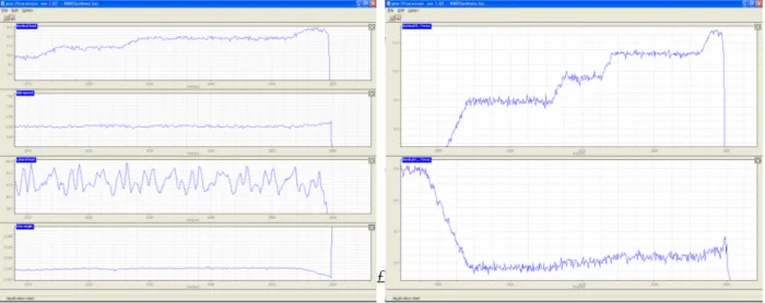
이 시험에서는 실제 탈선이 발생할 때까지 파라미터를 단계적으로 변경하여 실제 탈선상황을 재현하였다. 초기 Vertical load는 -40kN, 50%로 설정하고 Rail speed를 10km/h로 구동하며 Lateral load와 Yaw angle 을 서서히 증가 시켜 보았으나 별다른 변화가 보이지 않았으며 Yaw angle을 -방향으로 서서히 변화시켜 가 며 Rail speed를 8km/h로 낮춘 뒤 Lateral load를 약 42kN까지 인장시켜 보았다. Lateral load가 약 30kN을 넘어서면서부터 Wheel에 진동이 발생하기 시작하였으며 이후 Vertical load를 +방향으로 서서히 증가시켜가 며 테스트 중 Wheel의 flange가 Rail 위에 얹혀지면서 실제 탈선이 발생하였다. 탈선상황에서의 데이터와 확 대 데이터는 그림 1~3과 같다.
그림 1 Derailment test result
4. 결론 탈선은 횡압의 증가, 윤중의 감소 등의 탈선요인이 단일 요인으로 작용할 때에는 발생하기 어려웠으며, 횡 압의 증가와 윤중의 감소가 발생하면서 동시에 공격각이 증가할 때에 비로소 탈선상황이 발생하는 것을 알 수 있었다. 따라서 탈선 시험시에는 안전을 최우선적으로 고려하여 각 파라미터값을 단계적으로 변경하 여야 하며, 향후 다양한 탈선영향인자에 대한 검토가 계속해서 이루어져야 한다. 참고문헌
1. Simon Iwnicki, “ Handbook of Railway Vehicle Dynamics ”, CRC Press, 2006.
2. International Union of Railways, “Testing and approval of railway vehicles from the point of view of their dynamic behaviour - Safety - Track fatigue - Running behaviour, 4th Edition,” UIC CODE 518, 2009. 3. Young Sam Ham, Dong Hyung Lee, Seok Jin Kwon, Jung Won Seo, “The experiment study about a
correlation between the derailment coefficient of the railway vehicle and the track alignment,” Journal of the Korean Society for Precision Engineering, Vol. 27, No. 8, pp. 7-12, 2010.
4. S. D. Iwnicki, A. H. Wickens, “ Validation of a MATLAB railway vehicle simulation using a scale roller rig ”, Vehicle System Dynamics, pp. 257~270, 1998.
5. A. Jaschinski, H, Chollet, S. D. Iwnicki, A. H. Wickens, “ The Application of roller rigs to railway vehicle dynamics ” , pp. 345~392, 1998.