ISSN 1225-7842 / eISSN 2287-402X http://dx.doi.org/10.7779/JKSNT.2017.37.2.99
1. Introduction
1.1. Study Background and Objectives
Composite materials used for manufacturing the aircraft need to tolerate various loads continuously. Therefore, they must be built strong enough to bear these loads and maintain their shape safely. Parts of the aircraft are exposed to high temperature and high humidity environments frequently and repeatedly due to the nature of aviation. When these composite materials are repeatedly exposed to external moisture and heat for an extended time, moisture can infiltrate into the composite materials and result in moisture-impregnating defects. The infiltrated moisture in the composite materials can be frozen and abruptly change the physical
attitudes to the materials. Consequently, it becomes a major factor deforming or destroying the materials. This study used infrared ther- mography nondestructive testing (IRT-NDT) in order to detect the moisture-impregnating defects of composite materials [1]. IRT-NDT is a defect detecting method, which detects infrared radiated from a specimen, converts the changes in the energy intensity of infrared light into electric signals, and displays the temperature distribution of the specimen. It is a non-destructive testing technology that can detect the physical attributes and defects of a material without destroying a product. It can be applied to wind turbine blades, aircraft bodies, industrial equipment, plants, structures, and welded joints. IRT can detect the defect images of a target object without a contact because it uses the infrared
Detecting the Honeycomb Sandwich Composite Material’s Moisture
Impregnating Defects by Using Infrared Thermography Technique
Koo-Ahn Kwon*, Hee-Sang Park**✝, Man-Yong Choi*, Jeong-Hak Park* and Won-Jae Choi*Abstract Many composite materials are used in the aerospace industry because of their excellent mechanical properties. However, the nature of aviation exposes these materials to high temperature and high moisture conditions depending on climate, location, and altitude. Therefore, the molecular arrangement chemical properties, and mechanical properties of composite materials can be changed under these conditions. As a result, surface disruptions and cracks can be created. Consequently, moisture-impregnating defects can be induced due to the crack and delamination of composite materials as they are repeatedly exposed to moisture absorption moisture release, fatigue environment, temperature changes, and fluid pressure changes. This study evaluates the possibility of detecting the moisture-impregnating defects of CFRP and GFRP honeycomb structure sandwich composite materials, which are the composite materials in the aircraft structure, by using an active infrared thermography technology among non-destructive testing methods. In all experiments, it was possible to distinguish the area and a number of CFRP composite materials more clearly than those of GFRP composite material. The highest detection rate was observed in the heating duration of 50 mHz and the low detection rate was at the heating duration of over 500 mHz. The reflection method showed a higher detection rate than the transmission method.
Keywords: CFRP, GFRP, Honeycomb Structure, Infrared Thermography, Lock-in Method
[Received: March 18, 2017, Revised: April 23, 2017, Accepted: April 24, 2017] *Safety Measurement Center, Korea Research Institute of Standards and Science, Daejeon 34113, Korea, **R&D, Korea Research Institute of Smart Material and Structures System Association, Daejeon 35222, Korea, ✝Corresponding Author: [email protected]
technology, which can detect the defects of the aircraft, a large structure, quickly without contacting it. Consequently, the objectives of the study were to develop an active IRT technology system by using a light source as a heat source to detect the moisture-impregnating defects of composite materials and detect the moisture- impregnating defects occurring in CFRP and GFRP honeycomb sandwich composites [2].
2. Materials and Devices
Various types, sizes, and depths of defects were fabricated by using composite materials to test if IRT could detect internal defects in honeycomb sandwich composite materials.
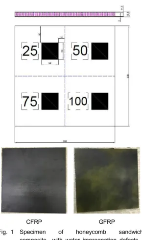
CFRP and GFRP were used for the upper and lower surfaces of the honeycomb sandwich composite test specimens (Fig. 1). The used CFRP specimen was 300.0 × 300.0 mm in size and 2.0 mm in thickness. SKYFLEX WSN3KY (SK Chemicals) and Mitsubushi Rayon TR-30 (carbon fiber) were used. GFRP composite specimen was GEP7628 and E-glass was applied. The used honeycomb material was made by ACT Aero Grade Aramid Honeycomb (ACT). Heat resistant phenolic resin was coated on Nomax T412 aramid paper. The cell size was 3.2 mm and the thickness was 10 mm. In order to simulate moisture-impregnation defects, the specimens were divided into four equal pieces. Honeycomb cores were fabricated with containing different amounts of moisture in order to evaluate if they can be distinctively
detected by IRT under different conditions. The moisture defects were fabricated in the number shapes and a square shape and each cell were fabricated by inserting moisture at 25, 50, 75, and 100 % depths.
3. Experiment Methods
Defect detection methods using IRT can be divided into passive methods and active methods. Passive methods detect defects by processing response signals of a target object by transmitting a specific stimulus source of the target object as a harmonic function, unlike active methods. In order to detect defects in honeycomb sandwich composite, this study used the lock in phase technology, which can convert thermography into a signal in a conventional IRT system to effectively detect the defects of
CFRP GFRP
Fig. 1 Specimen of honeycomb sandwich composite with water impregnation defects
flat plate specimens. The IRT testing device is composed of a light source heating device and an IRT camera. Moreover, the testing device was installed in a thermally insulation chamber to minimize the heat exchange between the test specimens and the outside. Two 1.0 kW halogen lamps were installed as a light source 1.0 m away from the specimens. Reflection and transmission heating methods were separately used to test the detection rate of defects according to the heating direction (Fig. 2 & 3). Moreover, the characteristics of the detection rate by heating time was studied by conducting tests at different heating durations (i.e. 50, 100, 200 and 500 mHz) [3]. With reference to the previous experiments, the heating durations were classified. Silver 420m model (NETD: 25 mK, Cedip, France) was used as an IRT camera. The surface of specimens was painted with black matte paint in order to satisfy the near black
condition with a complete emissivity value of 1, which was required to increase the IRT detection sensitivity. Moreover, the experiment was conducted by dividing the testing surface into CFRP and GFRP in order to understand the characteristics of the defect detection rate according to the CFRP and GFRP composite materials [4,5].
4. Discussion
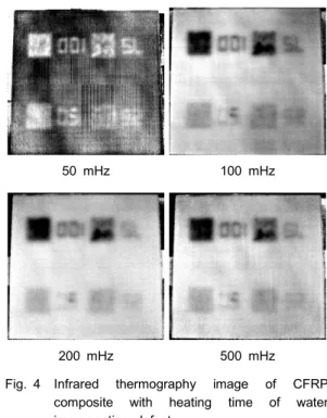
Fig. 4 shows the images of defects on the measurement surface of CFRP composite using the reflection heating method. The most distinct defect image was acquired at 50 mHz heating duration. Similar defect detection rates were found at other heating durations (i.e., 100, 200, and 500 mHz). Moreover, moisture-impregnating defects infiltrating to 100% depth were most distinctly detected and those in the 75% were the second. The detection rate was the lowest at the 50 and 25% depth defects and defect detection at these depths showed similar defect
Fig. 2 Reflection method
Fig. 3 Transmission method
50 mHz 100 mHz
200 mHz 500 mHz
Fig. 4 Infrared thermography image of CFRP composite with heating time of water impregnation defect
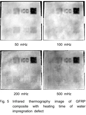
images. The image of defects in the GFRP composite material is shown in Fig 5. The results of the experiment showed that the images of the most distinct defects could be acquired at the heating during of 50 mHz and only the moisture-impregnating defects at 100% depth was clearly observed. The defect detection rate was similar in other depths. Additionally, the measurement of the CFRP composite material revealed a higher defect detection rate than that of the GFRP composite material due to the nature of composite materials.
Table 1 showed if moisture-impregnated defects at 75% depth could be detected.
The characteristics of defect detection were compared based on the moisture-impregnating defects at the 75% depth because the moisture- impregnating defects at the 100% depth showed a high defect detection rate regardless of heating duration and composite material type.
Table 2 showed if moisture-impregnated defects at 75% depth could be detected (Transmission).
Table 2 Detection of defects according to frequency (transmission)
O:possible X:Impossible △: uncertain
50 (mHz) 100 (mHz) 200 (mHz) 500 (mHz) Number. CFRP O O △ △ GFRP △ △ X X Squar CFRP O O O △ GFRP △ △ △ X
Fig. 6 shows defects when they were measured by the transmission method (among heating methods). It shows the image of a defect when light source was heated by GFRP and the CFRP composite material on the opposite side was measured by an infrared camera. The most distinct image of defects was acquired at the heating duration of 50 mHz, just like the reflection method. The image of moisture-impregnating defects at 25% depth could be obtained faintly. At the heating duration of 100 mHz, number and area could be detected for all defects except defects at 75% depth. However, at the heating duration of 200 and 500 mHz, it was hard to read the area or number of moisture-impregnating defects at 25 and 50%.
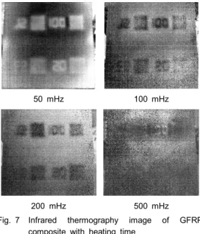
Fig. 7 shows the image of defects at the GFRP composite material measurement surface measured by the transmission heating method. The most distinctive defect image was obtained from the heating duration of 50 mHz. The image of 25% depth moisture impregnating defects could be detected faintly. For the heating
200 mHz 500 mHz
Fig. 5 Infrared thermography image of GFRP composite with heating time of water impregnation defect
duration of 100 mHz, the number and area of could be detected for 25 and 50% depths, not in 75 and 100% depths. For the heating duration of 200 mHz, it was possible to identify the area of moisture-impregnating defects at 25, 50, and 75%, but it was hard to read numbers. At the heating duration of 500 mHz, it was impossible to identify numbers and area at all depths.
50 mHz 100 mHz
200 mHz 500 mHz
Fig. 6 Infrared thermography image of CFRP composite with heating time
50 mHz 100 mHz
200 mHz 500 mHz
Fig. 7 Infrared thermography image of GFRP composite with heating time
Fig. 8 Temperature change of moisture impregnation defects with heating time (200 MHz: reflection method)
Fig. 9 Temperature change of moisture impregnation defects with heating time (200 mHz: trans- mission method)
Reflection method increased 4.7°C for 60 seconds at a location containing 100% moisture while it increased 7.6°C for 60 seconds at a location containing 50% moisture (Fig. 8).
60 seconds at a location containing 100% moisture while it increased 3.0°C for 60 seconds at a location containing 50% moisture (Fig. 9).
The transmission method increased 2.2°C for Fig. 8 shows that the difference in temperature becomes larger because of the difference in latent heat. The reflection method measures defects on the same surface, where it is heated. Therefore, it had a higher temperature change than the transmission method did because the transmission method lost much energy while energy was conducted to the moisture through composite material and sandwich panel.
5. Conclusions
This study was conducted to analyze the defect detection characteristics of CFRP and GFRP composite materials at different light source heating durations and heating directions for detecting the moisture-impregnating defects of honeycomb sandwich composite material by using the IRT technology.
1) In all experiments, it was possible to distin- guish the area and a number of CFRP composite material more clearly than those of GFRP composite material. For CFRP composite material, it was possible to identify the area and number of moisture-impregnating defects
over 500 mHz. It was possible to determine the area and the number of defects regardless of the composite material.
3) The analysis of defect detection characteristics of moisture-impregnating depth showed that the detection rate was the highest at the 100% depth moisture-impregnating defects. Contrarily, it was the lowest at the 25% depth.
4) The reflection method showed a high
detection rate than transmission method did. 5) It was confirmed that the temperature difference
gradually increased with time according to the difference in the heat capacity of the water inserted into the test specimen.
Acknowledgements
This study is a research project performed asa a part of the middle-grade researcher supporting program with the support of the National Research Foundation of Korea and the Ministry of Science, ICT and Future Planning (2015R1A2A2A01005426).
This research was supported by Korean Research Institute of Standard and Science (KRISS-2017-17011069).
References
[1] X. P. V. Maldague, "Theory and Practice of Infrared Technology for Nondestructive Testing," John Wiley & Sons, New York (2001)
[2] G. Gaussorgurs, "Infrared Thermography," Translated by S. Chomet, Champman & Hall, London, pp. 415-452 (1994)
[3] M. Y. Choi, H. S. Park, J. H. Park, W. T. Kim and W. J. Choi. "Study on the qualitative defects detection in composites by optical infrared thermography," Journal of the Korean Society for Nondestructive Testing, Vol. 31, No. 2, pp. 150-156 (2011)
[4] G. Busse, D. Wu and W. Karpen, "Thermal wave imaging with phase sensitive modulated thermography," J. Appl. Phys., Vol. 71, No. 8, pp. 3962-3965 (1992)
[5] V. P, Vavilov, "Infrared and thermal testing: heat transfer," Nondestructive Testing Handbook Series Ⅲ (3rd Ed.), X. P. V. Maldague Maldague, P. O. Moore Ed., ASNT, Columbus, USA, pp. 54-86 (2001)