Method of Controlling Four Sets of Permanent Magnet
Synchronous Motor by One Inverter on a Railway Vehicle
Takuma Ito
*, Hiromi Inaba
*, Keiji Kishine
*, Mitsuki Nakai
**,
and Keisuke Ishikura
*Abstract
– If it were possible to control four sets of PMSMs in place of induction motors byusing one inverter, we could attain efficient driving trains. In this paper, a method for controlling three sets of PMSMs with one inverter is shown. Additionally, this shows the method to control four sets of PMSMs with one inverter and the results of a simulation with the proposed method.
Keywords:
Multi motor drive, Railway vehicle, Synchronous machine1. Introduction
Recently, trains have been driven by mainly operating four sets of induction motors with one inverter. Using a permanent magnet synchronous motor (PMSM) is more efficient than using an induction motor. Therefore, at ICEMS 2013, we proposed a method for controlling two sets of PMSMs with one inverters [1]. As further development, in this paper, we show a method for controlling three and four sets of PMSMs, for which the magnetic pole positions differ, with one inverter.
2. Previously Control Method for Two Sets of
PMSM
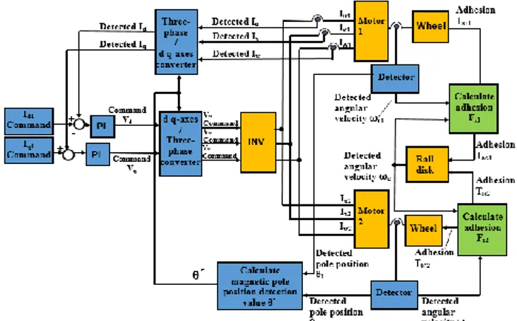
If two motors that have differing magnetic pole positions are applied with the same three-phase voltage, a difference in the torque and current of the two motors arises from the difference in the magnetic pole position. This was found in the previously announced paper [1]. Therefore, to simultaneously control two PMSMs, it is necessary to control the state in which the magnetic pole positions are in the same position. Therefore, a control method was proposed that adjusts the position of the magnetic poles, and next, vector control is performed for motor 1, which is shown at the top of Fig. 1. Fig. 1 is a block diagram of the proposed control for two motors, and Fig. 2 shows a control flowchart of the proposed control for two motors. When the magnetic
Fig. 1. Overall structure of proposed method
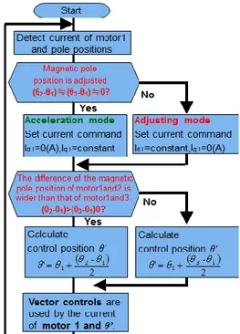
Fig. 2. Flowchart of control method for two sets of PMSM
pole positions are in the same position (θ1 - θ2 = 0), motors 1 and 2 are performed acceleration control by ordinary vector control. The magnetic pole positions of motors 1 and 2 are * Dept. of Electronic Systems Engineering, the University of Shiga
Prefecture, Japan. (zn23titou@ec.usp.ac.jp, inaba.h@usp.ac.jp, kishine.k@usp.ac.jp, zn23kishikura@ec.usp.ac.jp)
** Ishida Co., Ltd., Japan. (mimimi.mitsuki@gmail.com)
Takuma Ito, Hiromi Inaba, Keiji Kishine, Mitsuki Nakai , and Keisuke Ishikura 404 θ1 and θ2. When the magnetic pole positions are different,
the positions of the two motors are adjusted by the proposed adjustment control. The proposed control is described by using a vector diagram.
Simultaneous equations of the d, q-axis coordinate system of a PMSM are given by 0 q d q a d q d a q d i i pL R L L pL R V V (1)
In (1), ψ is the effective value of the armature flux linkage caused by the permanent magnet, ω is the angular velocity electricity, Ra is the armature winding resistance, p is the differential operator, Vd, Vq is the d, q-axis component of the armature voltage, Id, Iq is the d, q-axis component of the armature current, and Ld, Lq is the d, q axis Inductance.
Fig. 3 shows a vector diagram in for the case of performing the proposed control method for the motors 1 and 2 when the motors are stopped. Proviso As shown in Fig. 3, the motors 1 and 2 are stopped in a state that in which their magnetic pole positions are different from by 120 degrees. By performing the control proposed in Fig. 2, the torque current Iq of different codes flows to each both motors 1, 2, as shown in Fig. 3. And, each motor rotates in each match direction of matching the magnetic pole positions, so the pole position is adjusted.
Next, Fig. 4 shows a vector diagram for the case of performing the proposed control method for motors 1 and 2 when the motors are rotated. As shown, the motors are rotated in a state in which their magnetic pole positions are different by 60 degrees. By performing the proposed control as well while rotating, the torque current Iq of different codes flows to each motor, and each motor rotates in each direction matching the magnetic pole positions, so the pole position is adjusted.
3. Control Method for Three Sets of PMSM
A method for controlling three sets of PMSMs is proposed in this section. The control method proposed is similar to that for controlling two motors. First, regarding the current to be detected, the current flowing to motor 1 is detected. The control is considered separately in when the magnetic pole positions are different and when they are in the same position.
In the case of two motor control, the magnetic pole positions of the two motors are adjusted by using the the proposed control if the magnetic pole positions are different. This proposed adjustment control is for two motors.
Therefore, it is divided into the following two patterns for position adjustment in order to adjust the position of the control for three motors.
Fig. 3. Vector diagram in case of performing the proposed
control method (motors 1 and 2 are stopped)
Fig. 4. Vector diagram in case of performing the proposed
control method (motors 1 and 2 are rotated)
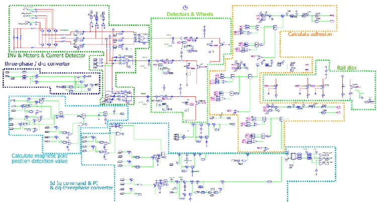
Fig. 6. Overall view of circuit on simulator (PSIM) for three PMSMs
A. “The pole position difference between motors 1 and 2 is greater than that between the magnetic pole positions of motors 1 and 3 (θ2 - θ1) > (θ3 - θ1).”
In this case, control of the positioning of motors 1 and 2 is performed.
B. “The pole position difference between motors 1 and motor 3 is greater than that between the magnetic pole positions of motors 1 and 2 (θ3 - θ1) > (θ2 - θ1).”
In this case, control of the magnetic pole position adjustment of motors 1 and 3 is performed.
We propose using this method to control the magnetic pole position adjustment of the three motors.
When the magnetic pole positions are in the same position, the current command value is controlled with Iq1 = constant, Id1 = 0, and ordinary vector control is performed.
Fig. 5 shows a control flowchart of the proposed method for three motors. A description is given below.
First, the current value of motor 1 and the magnetic pole positions of the motor are detected. Next, when the magnetic pole positions are in the same position (θ1 = θ2 = θ3), the current command value is controlled by Iq1 = constant, Id1 = 0, and motors 1, 2, and 3 are performed acceleration control by ordinary vector control. When the magnetic pole positions are different, the current command value is controlled by Iq1 = 0, Id1 = constant. Thereby, the regulatory control of the magnetic pole position is performed.
After, to perform magnetic pole position adjustment control of the three motors, it is necessary to determine the
detected magnetic pole position θ' by using the magnetic pole position of the motor. When (θ2 - θ1) > (θ3 - θ1), θ' is set to θ´ = θ1 + (θ2 - θ1)/2. When (θ2 - θ1) < (θ3 - θ1), θ' is set to θ´ = θ1 + (θ3 - θ1)/2. Then, vector control is performed by using the magnetic pole position θ' and the current of motor 1.
Fig. 6 shows an overall view of a circuit on simulator (PSIM) for three PMSMs. Fig. 7 shows the overall structure of the proposed method for the three PMSMs.
Fig. 7. Overall structure of proposed method for three
PMSMs
4. Simulation Results for The Three PMSMs
The proposed control was performed when the pole positions differences were θ2 - θ1 = 120 degrees and θ3 - θ1 =
Takuma Ito, Hiromi Inaba, Keiji Kishine, Mitsuki Nakai , and Keisuke Ishikura 406 -60 degrees. Fig. 8 shows the simulation results of the pole
positions of motors 1, 2 and 3, which are θ1 (°), θ2 (°), and θ3 (°), the differences in the magnetic pole position, which are θ2 - θ1 (°) and θ3 - θ1 (°), the peripheral velocities of the wheels of motors 1, 2, and 3, which are Vr1 (m/s), Vr2 (m/s), and Vr3 (m/s), and the peripheral velocity of the rail disk Vc (m/s). The control of shifting the magnetic pole position was performed until t = 1 so as to determine whether or not simulation can be able to make adjustments with the proposed control from when the magnetic pole positions are different. Therefore, Fig. 8 shows the results after t = 1(s), which is when the proposed control began to actually be performed.
From Fig. 8, since the difference of the magnetic pole position became 0 at t ≈1.2 (s), it turns out that the magnetic pole positions could be adjusted. Additionally, it was confirmed that the control for acceleration thereafter was performed. Therefore, it was possible to control the three PMSMs by using one inverter with the proposed control method.
5. Control Method for Four Sets of PMSM
A control method for four sets of PMSMs is proposed in this section. The control method proposed is similar to the method for controlling three motors. First, for the current to be detected, the current flowing to motor 1 is detected. The control is considered separately when the magnetic pole positions are different and when they are in the same position. When the magnetic pole positions are different, those of the two motors are adjusted by using the proposed control the same as in the case of three PMSMs. In the case of four motors, it is divided into the three following patterns for position adjustment in order to adjust the position of the control for four motors.
A. “The magnetic pole position difference between motors 1 and 2 is larger than those for motor 1 and the other motors.”
In this case, control of the magnetic pole position adjustment of motors 1 and 2 is performed.
B. “The magnetic pole position difference between motors 1 and 3 is larger than that between motor 1 and the other motors.”
In this case, control of the magnetic pole position adjustment of motors 1 and 3 is performed.
C. “The magnetic pole position difference between motors 1 and 4 is larger than that between motor 1 and the other motors.”
In this case, control of the magnetic pole position adjustment of motors 1 and 4 is performed.
Fig. 8. Result of controlling three sets of PMSM with
proposed method.
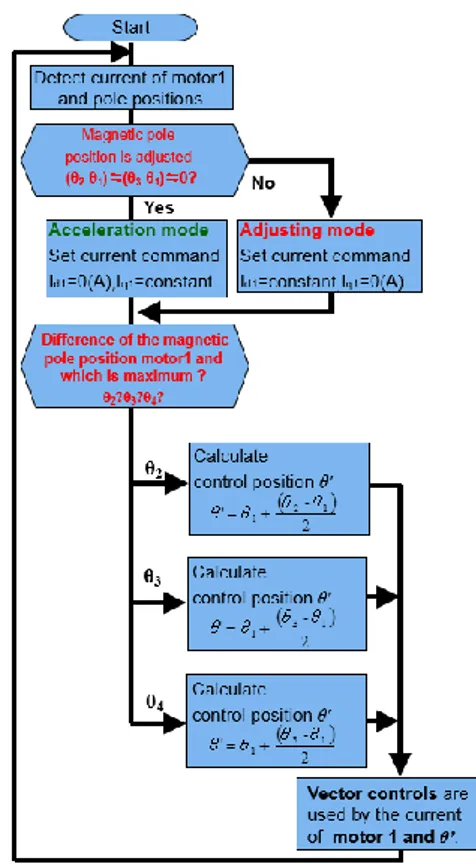
Fig. 9. Flowchart of control method for four PMSMs
Fig. 10. Overall structure of proposed method for four
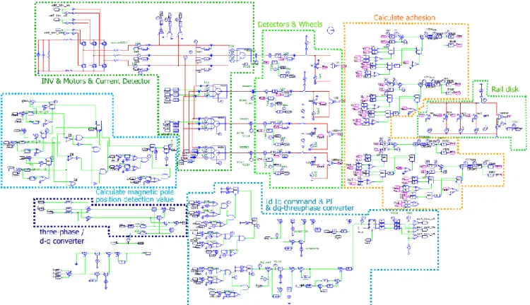
Fig. 11. Overall view of circuit on simulator (PSIM) for four PMSMs
When the magnetic pole positions are in the same position, the current command value is controlled with Iq1 = constant, Id1 = 0, and ordinary vector control is performed. Fig. 9 shows a control flowchart of the proposed method for four PMSMs. Fig. 10 shows the overall structure with the proposed method for four PMSMs. Fig. 11 shows an overall view of a PSIM for four PMSMs. A description of the flowchart in Fig. 9 is given below. First, the current value of motor 1 and the magnetic pole positions of the motor are detected. Next, when the magnetic pole positions are in the same position (θ1 = θ2 = θ3 = θ4), the current command value is controlled with Iq1 = constant, Id1 = 0, and motors 1, 2, 3 and 4 perform undergo acceleration control by ordinary vector control. When the magnetic pole positions are different, the current command value is controlled with Iq1 = 0, Id1 = constant. Thereby, the regulatory control of the magnetic pole position is performed. After, to perform magnetic pole position adjustment control of the four motors, it is necessary to determine the detected magnetic pole position θ ' by using the magnetic pole position of the motor. For the pole position differences between motor 1 and the other motors, (θ2 - θ1), (θ3 - θ1), and (θ4 - θ1), it is necessary to determine what the maximum is. In the case of (θ2 - θ1), θ ' is set to θ´ = θ1 + (θ2 - θ1)/2. In the case of (θ3 - θ1), θ ' is set to θ´ = θ1 + (θ3 - θ1)/2. In the case of (θ3 - θ1), θ ' is set to θ´ = θ1 + (θ3 - θ1)/2. Then, vector control is performed by using the magnetic pole position θ 'and the current of motor 1.
Fig. 12. Result of controlling four PMSMs with proposed
method.
6. Simulation Results for The Four PMSMs
The proposed control was performed when the pole position differences were θ2 - θ1 = -300 degrees, θ3 - θ1 = -120 degrees, and θ4 - θ1 = -220 degrees. Fig. 12 shows the simulation results of the pole positions of motors 1, 2, 3, and 4, which are θ1 (°), θ2 (°), θ3 (°), and θ4 (°), the differences in the magnetic pole positions, which are θ2 - θ1 (°), θ3 - θ1 (°), and θ4 - θ1 (°), the peripheral velocities of the wheels of motors 1, 2, 3, and 4, which are Vr1 (m/s), Vr2 (m/s), Vr3 (m/s), and Vr4 (m/s), and the peripheral velocity of the rail disk Vc (m/s). The control of shifting the magnetic pole position was performed until t=1 so as to determine whether or not simulation could be able to make adjustments with the
Takuma Ito, Hiromi Inaba, Keiji Kishine, Mitsuki Nakai , and Keisuke Ishikura 408 proposed control from when the magnetic pole positions
were different. Therefore, Fig. 12 shows the results after t=1(s), which is when the proposed control began to actually be performed. From Fig. 12, since the difference of the magnetic pole positions became 0 at t ≈ 1.2 (s), it turns out that the magnetic pole positions could be adjusted, and it was confirmed that the control to accelerate thereafter was performed. Therefore, it was possible to control the four PMSMs with one inverter by using the proposed control method.
7. Conclusion
We proposed a method for controlling three or four PMSMs with one inverter. As a result of having performed the proposed control method, three and four sets of PMSMs were able to be controlled by adjusting the magnetic pole positions with one inverter.
Acknowledgements
The authors thank everyone in the Electronics Circuit Laboratory, Department of Electronic Systems Engineering, School of Engineering, the University of Shiga Prefecture.
References
[1] T. Itou et al., “Method controlling two or more sets of PMSM by one inverter on a railway vehicle,” ICEMS, SMD-1321, 2013
Takuma Ito received the B.S. degree of
electronic systems engineering from The University of Shiga Prefecture in 2013. Since the same year, he has enrolled a master’s course Graduate school of Engineering in The University of Shiga Prefecture. His research interests are an inverter and a multi motors drive.
Hiromi Inaba was born in Tokyo, Japan, on
September 1, 1950. He received the B.S. and Dr. Eng. degrees from Hokkaido University, Hokkaido, Japan, in 1974 and 1997, respectively. In 1974 he joined Hitachi Research Laboratory, Hitachi, Ltd., Ibaraki, Japan. He has been engaged in research and development on an elevator and steel control system. In 2008, he became a Professor with the school of engineering, The University of Shiga prefecture, Shiga, Japan. Dr. Inaba is a member of the IEEE Industry Applications Society (IAS) and the Institute of Electrical Engineers (IEE) of Japan.
Keiji Kishine was born in Kyoto, Japan, on
October 26, 1964. He received the B.S., and M.S. degrees in engineering science from Kyoto University, Kyoto, Japan, and Ph.D. degree from in informatics from Kyoto University, Kyoto, Japan, in 1990, 1992, and 2006, respectively. In 1992, he joined the Electrical Communication Laboratories, Nippon Telegraph and Telephone Corporation (NTT), Tokyo, Japan. He has been engaged in research and design of high-speed, low-power circuits for Gbit/s LSIs using Si-bipolar transistors, with application to optical communication systems in NTT System Electronics Laboratories, Kanagawa, Japan. From 1997, he has been worked on research and development of over Gbit/s Clock and Data Recovery IC at Network Service Innovation Laboratory in NTT Network Innovation Laboratories, Kanagawa, Japan. Now, He is working at Ubiquitous Interface Laboratory in NTT Microsystems Integration Laboratories, Kanagawa, Japan. In 2008, he became an Associate Professor with the school of engineering, The University of Shiga prefecture, Shiga, Japan. Dr. Kishine is a member of the IEEE Solid-State Circuits Society (SSCS) and Circuits and Systems (CAS), the Institute of Electronics, Information and Communication Engineers (IEICE) of Japan, the Institute of Electrical Engineers (IEE) of Japan.
Mitsuki Nakai received the B.S. and M.S.
degrees of electronic systems engineering from The University of Shiga Prefecture in 2012 and 2014. In 2014, he joined Ishida Co., Ltd., Shiga, Japan. His research interests are a parallel connected power converter and motor drive.
Keisuke Ishikurareceived the B.S. degree of electronic systems engineering from The University of Shiga Prefecture in 2013. Since the same year, he has enrolled a master’s course Graduate school of Engineering in The University of Shiga Prefecture. His research interests are a parallel connected power converter and motor drive.