DYNAMIC DESIGN METHODS OF ROCK ENGINEERING
Xia-Ting FengState Key Laboratory of Geomechanics and Geotechnical Engineering, Institute of Rock and Soil Mechanics, Chinese Academy of Sciences, Wuhan 430071, China Email: [email protected]
SYNPOSIS:
The key features of an intelligent and dynamic design methodology for rock engineering projects has been introduced and summarized firstly, which include some new functions such as intelligent recognition of mechanical rockmass parameters, strategies to select modeling methods and codes, integrated feedback modeling and information, and technical auditing in rock engineering design process. Then typical examples of applications of the dynamic design methodology in some large slopes, underground powerhouses in China are summarized. The discussions are given for the future of the methodology.
1. INTORDUCTION
There have been many earlier presentations that have included rock engineering design flowcharts: e.g. the flowcharts developed by Hoek and Brown (1977), Pahl and Beitz (1984), Brady and Brown (1985), Bieniawski (1984, 1992, 1993), Hudson (1993), and more recently through the work of Li (1998), AFTES (2003), Feng et al. (2003), Goricki (2003), Goricki et al. (2004), Eurocode 7 Geotechnical Design (NF EN1997-1 Eurcode 7, 2005), Plmström and Stille (2007), Feng et al. (2007), Bond and Harris (2008), Read and Stacey (2010), Geotechnical Engineering Office (2009), and Austrian Society for Geomechanics (2010). In order to include intelligent recognition of mechanical rockmass parameters, strategies to select modeling methods and codes, integrated feedback modeling and information, and technical auditing in rock engineering design process, a new flowchart was proposed in 2007 (Hudson and Feng, 2007). It has been applied to a lot of large rock engineering projects design in China which has summarized in the book “Rock engineering design” (Feng and Hudson, 2011). This paper summarized the main features of dynamic design methodology and its further applications.
2. DYNAMIC DESIGN METHODS OF ROCK ENGINEERING
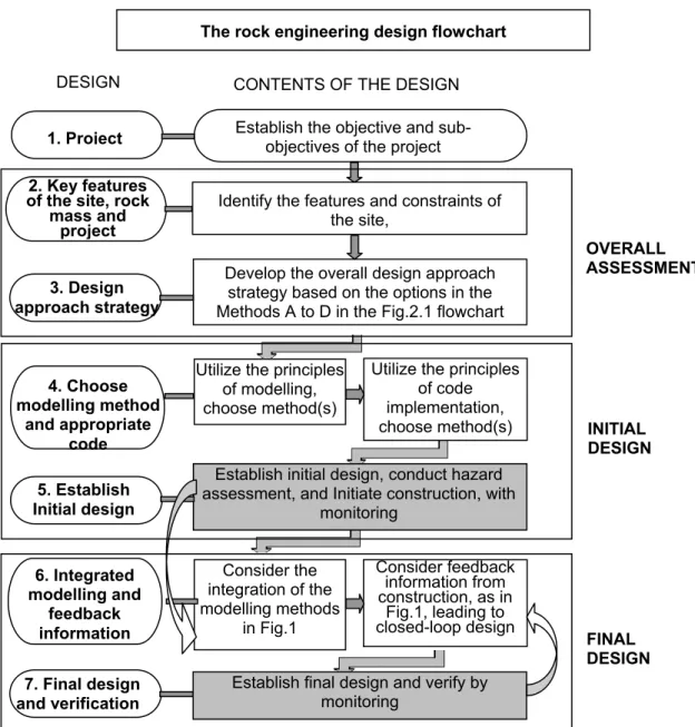
Fig.1 shows a new flowchart for rock engineering design in generally. It can be extended for the design of rock slopes and underground projects according to their various characters. Fig.2 shows a updated flowchart for underground powerhouse deign.
The new flowchart of rock engineering design has the following features.
1) Mechanical parameters in the excavation damage zone is corresponding to the degree of damage and its accumulation
Since there exists excavation damage zone after excavation of hard rock engineering and damage degree varies location from surface to deep surrounding rock (see Fig.3a and Fig.3b), mechanical parameters at excavation damage zone shall be corresponded to the damage degree. That means deformation modulus and strength parameters, such as cohesion and friction angle, are changed with damage degree of rock masses induced by excavation (see Fig.3c and Fig.3d). Also, excavation completed at multi-steps will induce accumulation of damage degree of rock masses. The mechanical parameters are also needed to be corresponded to the accumulation of damage degree. Therefore, the following equations are established as.
⎪
⎩
⎪
⎨
⎧
⋅
=
⋅
=
⋅
=
)
(
)
(
)
(
)
(
)
(
)
(
p o p d p C o p d p E o p df
f
C
C
f
E
E
ε
φ
ε
φ
ε
ε
ε
ε
φ (1)where
E
o ,C
o andφ
o are elastic modulus, cohesive strength and internal friction angle respectively in the elastic state of rock.(
p)
d
E
ε
,(
p)
dC
ε
and(
p)
dε
φ
are degenerative elastic modulus, degenerative cohesive strength and degenerative internal friction angle respectively in the yield state of rock while(
p)
E
f
ε
,(
p)
C
f
ε
andf
(
ε
p)
φ are the functions determining the changing trend of parameters.
Figure 1. Updated flowchart for the rock engineering design process (Hudson and Feng, 2007).
The rock engineering design flowchart
7. Final design and verification 6. Integrated modelling and feedback information 5. Establish Initial design 4. Choose modelling method and appropriate code 3. Design approach strategy 2. Key features of the site, rock mass and
project
1. Project Establish the objective and sub-objectives of the project
Identify the features and constraints of the site,
Develop the overall design approach strategy based on the options in the Methods A to D in the Fig.2.1 flowchart Utilize the principles
of modelling, choose method(s)
Utilize the principles of code implementation, choose method(s) Establish initial design, conduct hazard assessment, and Initiate construction, with
monitoring Consider the integration of the modelling methods in Fig.1 Consider feedback information from construction, as in Fig.1, leading to closed-loop design OVERALL ASSESSMENT INITIAL DESIGN FINAL DESIGN
DESIGN CONTENTS OF THE DESIGN
Establish final design and verify by monitoring
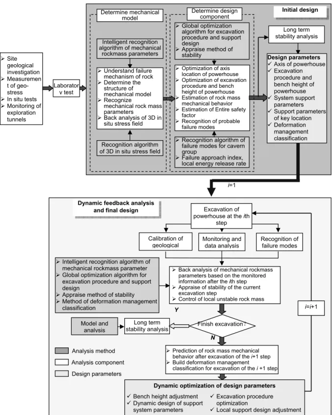
Figure 2. Dynamic feedback stability analysis and design optimization for large underground powerhouse which is excavated at multi steps.
¾Optimization of axis
location of powerhouse ¾ Optimization of excavation
procedure and bench height of powerhouse ¾ Estimation of rock mass
mechanical behavior ¾ Estimation of Entire safety
factor ¾ Recognition of probable failure modes Initial design Determine mechanical model Determine design component
Dynamic feedback analysis and final design
¾Back analysis of mechanical rockmass
parameters based on the monitored information after the ith step ¾ Appraise of stability of the current
excavation step
¾ Control of local unstable rock mass ¾ Intelligent recognition algorithm of
mechanical rockmass parameter ¾ Global optimization algorithm for excavation procedure and support design
¾ Appraise method of stability ¾ Method of deformation management
classification Long term stability analysis Model and analysis Calibration of
geological Monitoring and data analysis
Recognition of failure modes Y N i=i+1 Analysis method Analysis component Design parameters
¾Prediction of rock mass mechanical
behavior after excavation of the i+1 step ¾ Build deformation management
classification for excavation of the i +1 step
Long term stability analysis
Finish excavation?
¾Global optimization
algorithm for excavation procedure and support design ¾ Appraise method of stability Laborator y test ¾ Site geological investigation ¾ Measuremen t of geo-stress ¾ In situ tests ¾ Monitoring of exploration tunnels i=1 Excavation of powerhouse at the ith
step
Dynamic optimization of design parameters
9 Bench height adjustment 9 Dynamic design of support
system parameters
9 Excavation procedure optimization
9 Local support design adjustment Recognition algorithm
of 3D in situ stress field Intelligent recognition algorithm of mechanical
rockmass parameters
¾Recognition algorithm of
failure modes for cavern group
¾ Failure approach index, local energy release rate
Design parameters 9 Axis of powerhouse 9 Excavation procedure and bench height of powerhouse 9 System support parameters 9 Support parameters of key location 9 Deformation management classification ¾ Understand failure mechanism of rock ¾ Determine the structure of mechanical model ¾ Recognize
mechanical rock mass parameters
¾ Back analysis of 3D in situ stress field
(a) (b)
(c) (d)
Figure 3. Damage degree indicated by failure approach index, FAI, of surrounding rock varying with location at excavation damage zone after excavation of (a) the first step and (c) the second step. Elastic modulus corresponding to damage degree of surrounding rock after excavation of (b) the first step and (d) the second step.
The mechanical rockmass parameters are recognized by using intelligent back analysis. The methods include:-
z Integration of neural networks with numerical analysis, which the topology and connection weights of neural networks are recognized by using genetic algorithms, particle swarm optimization, etc.
z Integration of support machine vectors with numerical analysis, which support machine vectors are recognized by using genetic algorithms
The information used for back analysis include:-
z The monitored displacement increase induced by excavation, or
z The monitored displacement increase and excavation damage zone increase induced by excavation
2) Selection of modeling strategies and methods
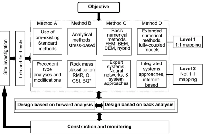
The eight methods in Level 1: 1:1 mapping and Level 2: not 1:1 mapping respectively can be selected, or developed if needed, for rock engineering design and modeling (Fig.4). The features and information required for different modeling methods are analyzed.
3) Design based on failure modes of rock mass.
The failure modes, geological conditions, and their control measures for large rock slopes, large cavern group, and tunnels are established respectively. The typical failure modes for rock slopes, underground rock cavern group and deep tunnels are recognized respectively. The failure modes are included in the database which are used for training expert systems, neural networks, or support vector machines. The established intelligent models can be used to recognize potential failure modes before and during the excavation with input of the recognized geological conditions. The numerical analysis is further used to recognized local unstable
F65
F85 E /GPa
F65 F85
blocks, calibrate the recognized failure modes, and evaluate effectiveness of the suggested support measures and excavation procedure.
Figure 4. Flowchart of rock mechanics modelling and rock engineering design approaches (Feng and Hudson, 2004)
4) The establishment of the deformation management classification for rock mass
The deformation management classification can be established from limited strain obtained from laboratory tests, empirical analogy and numerical analysis. Deformation characters of rock masses at different locations, including deformation increase and velocity, are important aspects to evaluate safety of large rock engineering. The deformation management classification can be used an index to evaluate safety of large rock engineering. It can be in three categories, such as “safe”, “warning”, and “dangerous” according to deformation increase and its velocity. The deformation character varies with locations, for example, arch crown, upper stream sidewall, and downstream sidewall of powerhouse and transformer chamber due to influence of in situ stress, strata and cavern shape and size. The corresponding deformation management classification has to thus be established for different location of large rock engineering and different rock engineering projects, including slopes, tunnels, cavern groups. The key issue is that how to establish a reasonable deformation management classification for various key location of large rock engineering.
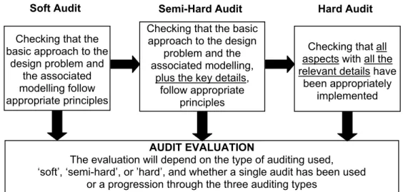
5) Technical auditing of modeling and design process
Within the context of this new rock engineering design methodology, it is of benefit to be able to formally audit the content of the rock mechanics modelling and rock engineering design of a project in order to ensure that all the necessary factors are included and that the technical work is correct. The key principles of an audit in general are that it is made according to evidence, known criteria and the current scientific framework. Auditing involves verification by evidence and the result is an opinion based on persuasive evidence. The audit should have an independent status, be free from investigatory and reporting constraints, produce a benefit, and result in a report. The audit result will always be an opinion – thus the auditing must carry
Objective Method A Lab an d field tests Use of pre-existing Standard methods
Construction and monitoring
Design based on forward analysis Design based on back analysis
Precedent type analyses and modifications Analytical methods, stress-based Integrated systems approaches, internet-based S ite invest ig at ion Level 2 Not 1:1 mapping Level 1 1:1 mapping
Method B Method C Method D
Basic numerical methods, FEM, BEM, DEM, hybrid Extended numerical methods, fully-coupled models Rock mass classification RMR, Q, GSI, BQ* Expert systems, Neural networks, & system approaches
authority. These principles apply to the specific case of technical auditing for rock mechanics modelling and rock engineering design and have therefore been adopted here (Fig.5).
6) Dynamic feedback stability analysis and design optimization method of large rock engineering projects.
It is not easy to understand geological conditions accurately of large rock engineering before the excavation which has to be calibrated during the excavation. The mechanical behavior of rock masses can be monitored during excavation and the monitoring information can be used for back analysis of mechanical parameters of rock masses. Therefore, dynamic feedback stability analysis and design optimization method is proposed for excavation of multi-steps which is shown in Fig.2. Before the excavation, the mechanical behavior of rock masses can be estimated with input of the deduced geological conditions and mechanical parameters estimated from the back analysis of the exploration tunnels and empirical analogy. After the excavation, the geological conditions are calibrated and the failure modes can be recognized. The control measures including excavation procedure and support design are suggested for unstable rock blocks and regions if needed. The monitored information is used for re-recognition of mechanical parameters of rock masses. The recognized mechanical parameters can be used to predict mechanical behaviors of rock masses after excavation of next step. The deformation management classification for excavation of next step can be suggested. The corresponding support design and excavation adjustment can be recommended accordingly. The dynamical feedback stability and design optimization process can be finished if the excavation at all steps is complete.
Figure 5. The ‘soft’, ‘semi-soft’ and ‘hard’ audits and the audit evaluation (Feng & Hudson, 2011) 7) Information management system
A 3D GIS system integrated stability analysis and design optimization was established to manage information collected in initial design and feedback and final design. The information related to the construction, support and strata evolution, monitoring and calculation. The analysis functions mentioned above are also included.
3. SUMMARY OF APPLICATIONS OF DYNAMIC DESIGN
METHODS IN ROCK ENGINEERING PROJECTS IN CHINA
This dynamic design methodology has been applied to some typical large rock slopes, underground powerhouses, deep tunnels, mining tunnels etc.(See Table 1 for typical examples).
Soft Audit Semi-Hard Audit Hard Audit
Checking that the basic approach to the
design problem and the associated modelling follow appropriate principles
Checking that the basic approach to the design
problem and the associated modelling,
plus the key details, follow appropriate
principles
Checking that all aspects with all the relevant details have
been appropriately implemented
AUDIT EVALUATION
The evaluation will depend on the type of auditing used, ‘soft’, ‘semi-hard’, or ’hard’, and whether a single audit has been used
The methods used for design optimization of large rock slopes and underground powerhouse (cavern group) are also summarized in Table 2 and 3 respectively.
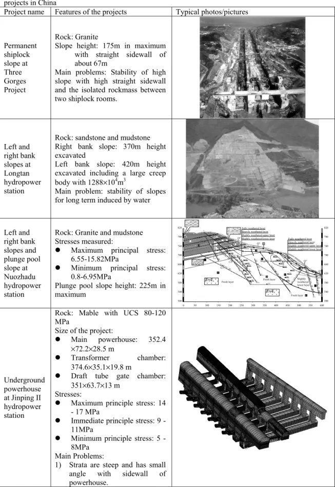
Table 1. Typical examples of applications of dynamic design methodology in large rock engineering projects in China
Project name Features of the projects Typical photos/pictures
Permanent shiplock slope at Three Gorges Project Rock: Granite
Slope height: 175m in maximum with straight sidewall of about 67m
Main problems: Stability of high slope with high straight sidewall and the isolated rockmass between two shiplock rooms.
Left and right bank slopes at Longtan hydropower station
Rock: sandstone and mudstone Right bank slope: 370m height excavated
Left bank slope: 420m height excavated including a large creep body with 1288×104m3
Main problem: stability of slopes for long term induced by water
Left and right bank slopes and plunge pool slope at Nuozhadu hydropower station
Rock: Granite and mudstone Stresses measured:
z Maximum principal stress: 6.55-15.82MPa
z Minimum principal stress: 0.8-6.95MPa
Plunge pool slope height: 225m in maximum N10▲ E,NW 40 ∠ °~ 50° N33▲W,NE 1∠ °0 N20 ▲~3 0▲W ,SW 50 ∠ °~ 60° N22▲W,SW 30 ∠ ° ~50° N10▲~20▲W,NE 1∠ °1- 15° N5▲ ,SW 62 ∠ ° N5▲W,SW 29 ∠ ° SN, W∠ 72° N0▲~1 0▲W ,SW 45 ∠ °~6 0° N 40▲ ~50▲ E,N W 75 ∠ ° ~85° N 10 ▲ ~38▲ E,N W 75 ∠ ° ~9 0° Fresh layer dl Q Qdl Fresh layer Slightly weathered lower layer Slightly weathered upper layer
Fresh layer
Fully weathered layer Heavily weathered layer Slightly weathered upper layer Slightly weathered lower layer Slightly weathered lower layer
Slightly weathered upper layer Heavily weathered layer Fully weathered layer
dl Q Qdl dl Q 500 540 580 620 660 700 740 780 820 600 550 500 450 400 350 300 250 200 150 100 50 0 820 780 740 700 660 620 580 540 500 . ... . ... . ... . . ... Underground powerhouse at Jinping II hydropower station
Rock: Mable with UCS 80-120 MPa
Size of the project:
z Main powerhouse: 352.4 ×72.2×28.5 m
z Transformer chamber: 374.6×35.1×19.8 m
z Draft tube gate chamber: 351×63.7×13 m
Stresses:
z Maximum principle stress: 14 - 17 MPa
z Immediate principle stress: 9 - 11MPa
z Minimum principle stress: 5 - 8MPa
Main Problems:
1) Strata are steep and has small angle with sidewall of powerhouse.
2) There are some steep faults having small angle with axis of main powerhouse.
3) Deformation of marble after strong relaxation has obvious time dependency.
4) There are some local weak strata unknown before excavation.
5) There are obvious relaxation and unloading influence of cross caverns with high sidewall of excavation. Underground powerhouse at Laxiwa hydropower station
Rock: granite with UCS MPa Size of the project:
z Main powerhouse: 312 ×75×32 m
z Transformer
chamber:232.6×53×29 m Stresses:
z Maximum principle stress: 22 - 29 MPa
z Minimum principle stress: 10MPa
Main problem: Stress failure of sidewall and arch crown of caverns and bus tunnels
Underground powerhouse at Shuibuya hydropower station
Rock: limestone with UCS 60-65MPa
Size of the project:
z Main powerhouse: 141 ×68×23 m
Main problems:
z Stability of sidewall with three soft layers with height of about 36.7% totally,
z Stability of rock crane beams z Stability of machine stable
foundation and crossover location of caverns Four deep headrace tunnels at Jinping II hydropower station
Rock: marble with UCS 80-120MPa
Depth: 1900-2525m Excavation methods: z TBM in 12.4m diameter
z Drilling and blasting in 13m in diameter
Maximum Principal Stress: about 70MPa
Main Problems: rockburst and water burst
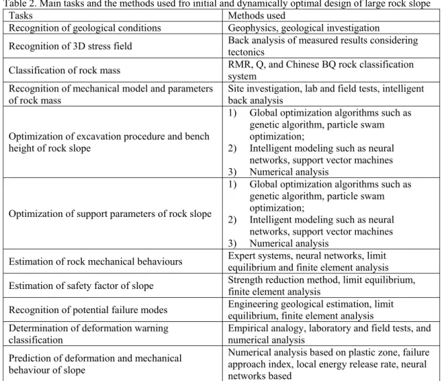
Table 2. Main tasks and the methods used fro initial and dynamically optimal design of large rock slope
Tasks Methods used
Recognition of geological conditions Geophysics, geological investigation
Recognition of 3D stress field Back analysis of measured results considering tectonics Classification of rock mass RMR, Q, and Chinese BQ rock classification system Recognition of mechanical model and parameters
of rock mass Site investigation, lab and field tests, intelligent back analysis Optimization of excavation procedure and bench
height of rock slope
1) Global optimization algorithms such as genetic algorithm, particle swam optimization;
2) Intelligent modeling such as neural networks, support vector machines 3) Numerical analysis
Optimization of support parameters of rock slope
1) Global optimization algorithms such as genetic algorithm, particle swam optimization;
2) Intelligent modeling such as neural networks, support vector machines 3) Numerical analysis
Estimation of rock mechanical behaviours Expert systems, neural networks, limit equilibrium and finite element analysis Estimation of safety factor of slope Strength reduction method, limit equilibrium, finite element analysis Recognition of potential failure modes Engineering geological estimation, limit equilibrium, finite element analysis Determination of deformation warning
classification
Empirical analogy, laboratory and field tests, and numerical analysis
Prediction of deformation and mechanical behaviour of slope
Numerical analysis based on plastic zone, failure approach index, local energy release rate, neural networks based
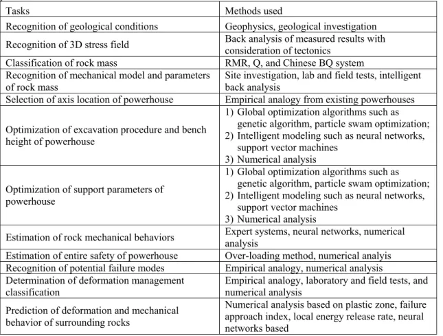
Table 3. Main tasks and their methods used fro initial and dynamic design of large underground powerhouse.
Tasks Methods used
Recognition of geological conditions Geophysics, geological investigation Recognition of 3D stress field Back analysis of measured results with consideration of tectonics
Classification of rock mass RMR, Q, and Chinese BQ system
Recognition of mechanical model and parameters
of rock mass Site investigation, lab and field tests, intelligent back analysis Selection of axis location of powerhouse Empirical analogy from existing powerhouses Optimization of excavation procedure and bench
height of powerhouse
1) Global optimization algorithms such as genetic algorithm, particle swam optimization; 2) Intelligent modeling such as neural networks,
support vector machines 3) Numerical analysis Optimization of support parameters of
powerhouse
1) Global optimization algorithms such as genetic algorithm, particle swam optimization; 2) Intelligent modeling such as neural networks,
support vector machines 3) Numerical analysis
Estimation of rock mechanical behaviors Expert systems, neural networks, numerical analysis Estimation of entire safety of powerhouse Over-loading method, numerical analyis Recognition of potential failure modes Empirical analogy, numerical analysis Determination of deformation management
classification
Empirical analogy, laboratory and field tests, and numerical analysis
Prediction of deformation and mechanical behavior of surrounding rocks
Numerical analysis based on plastic zone, failure approach index, local energy release rate, neural networks based
6. CONCLUSIONS
The dynamic design methodology started from learning and representing of empirical knowledge in rock mechanics and rock engineering. The initial expressions are establishment of expert system and neural network models for rock mechanics and rock engineering problems. And then it was developed to establish intelligent back analysis using displacement as back analysis information initially and extended to use both the monitored displacement and excavation damage zone as back analysis information. New indices such as local energy release rate and failure approach index are proposed to evaluate stability of rock engineering and rockburst risk. The establishment of dynamic control theory for rock mass stability indicated an integration of system process and multi task solving such as evaluation of geological condition and rock mass characters, intelligent recognition of mechanical parameters corresponding to damage degree, optimization of excavation procedure and bench parameter avoiding large stress and energy concentration induced by excavation and controlling energy release rate, optimization of support design, establishment of deformation warning classification, recognition of potential failure modes, and dynamic adjustment of excavation and support design. Now, it is focusing on safety of tunnel group at great overburden with high stress. These indicated that the complicated rock engineering problems has promoted the development of intelligent rock mechanics methodology. And, it has showed capability and potentiality of intelligent rock mechanics methodology to solve complicated rock engineering problems.
The further study on dynamic design methodology will at least focus on the following aspects: 1) Recognition of brittle mechanical models using the structure recognition algorithm
integrated with understanding of mechanism,
2) Establishment of indices assessing risks of structure slip rockburst,
3) Establishment of dynamic control theory of rock cavern group, deep tunnels, deep mining and design optimization methods.
AKNOWLEDGEMENT
This work is supported financially by China National Basic Research Program under Grant no. 2010CB732006 and China National Natural Science of Foundation under Grant no. 10872209. Professors Zhang Chunsheng, Wu Shiyong, Zhou Hui, Hou Jing, and Chen Xiangrong, and Dr. Zhang Chuanqing have given their contributions on the application of the methodology to design practice of the Jinping II underground powerhouse and headrace tunnels. Professor Zhou Hui, Zhang Zongliang, Dong Shaorao and Dr. Zhang Zhenhua gave their contributions for practice of methodology in hydraulic slope. They are all acknowledged.
REFERENCES:
1. AFTES.: Guidelines for Characterisation for Rock Masses Useful for the Design and the
Construction of Underground Structures. Version 1, June 2003.
2. Austrian Society for Geomechanics.: Guideline for the Geotechnical Design of Underground
Structures with Conventional Excavation. 2010.
3. Bieniawski, Z.T.: Classification of Rock Masses for Engineering: The RMR System and Future Trends. In: J.A. Hudson (Ed.): Comprehensive Rock Engineering, Vol. 3, Chapter 22,Elsevier, Oxford, 1993, pp. 553–573.
4. Bieniawski, Z.T.: Design Methodology in Rock Engineering: Theory, Education and Practice.Taylor & Francis, London, 1992, 205p.
5. Bieniawski, Z.T.: Rock Mechanics Design in Mining and Tunneling. A.A. Balkema, Rotterdam. 1984.
6. Bond, A. & Harris, A.: Decoding Eurocode 7. Taylor & Francis, London, 2008, 598p.
7. Brady, B.H.G. & Brown, E.T.: Rock Mechanics for Underground Mining. 3rd Edn., Kluwer Academic Publishers, Netherlands, 2004, 628p.
8. Feng, X.T. & Hudson, J.A.: The Ways Ahead for Rock Engineering Design Methodologies. Int. J.
Rock Mech. Min. Sci. 41 (2004), pp. 255–273.
9. Feng, X.T. & Hudson, J.A.: Rock Engineering Design. CRC Press, Taylor & Francis, London, 2011. 10. GEO Technical Guidance Note No. 25 (TGN25): Geotechnical Risk Management for Tunnel Works.
2009. Geotechnical Engineering Office, Civil Engineering and Development Department,Government of the Hong Kong Special Administrative Region.
11. Goricki, A.: Classification of rock mass behaviour based on a hierarchical rock mass
characterization for the design of underground structures. PhD thesis, 2003. Graz University of
Technology, Austria, 98p.
12. Goricki, A., Schubert, W. & Riedmueller, G.: New Developments for the Design and Construction of Tunnels in Complex Rock Masses. Int. J. Rock Mech. Min. Sci. 41 (2004), pp. 497–498.
13. Hoek, E. & Brown, E.T.: Underground Excavations in Rock. Inst. Min. Metall., London, 1977, 14. Hudson, J.A. (Ed): Comprehensive Rock Engineering. Elsevier, Oxford, 1993, 4407p.
15. Hudson, J.A. & Hudson, J.L.: Rock Mechanics and the Internet. Int. J. Rock Mech. Min. Sci. 34 (1997), 137p, full paper on CD.
16. Li, S.H., Wu, X.Y. & Ma, F.S.: Application of Precedent Type Analysis (PTA) in the Construction of the Ertan Hydro-Electric Station, China. Int. J. Rock Mech. Min. Sci. 35 (1998), pp. 787–795. 17. NF EN 1997-1 Eurocode 7, 2005. Calcul Géotechnique – Part 1: Règles generals.
18. Pahl, G. & Beitz, W.: Engineering Design., The Design Council, London, 1984. (2nd Edn. 1996 and 3rd Edn., 2007, Springer-Verlag, London).
19. Palmström, A. & Stille, H.: Ground Behaviour and Rock Engineering Tools for Underground Excavations. Tunn. Undergr. Sp.Tech. 22 (2007), pp. 363–376.
20. Read, J. & Stacey, P. (Eds.): Guidelines for Open Pit Slope Design. Taylor & Francis, & CSIRO Publishing, 2010, 512 p.