Development of a Safety Analysis Code for a Supercritical Water Cooled Reactor (SCWR)
Han Young Yoon,Soo Hyung Kim,Hee Cheol Kim, Yoon Yeong Bae
Fluid Engineering Division, Korea Atomic Energy Research Institute, 150 Deokjin Yuseong Daejeon,305-353, Republic of Korea, [email protected]
1. Introduction
Supercritical water-cooled reactor (SCWR) has been selected by GIF (Generation IV International Forum) as one of the promising nuclear reactor for the future and research activities are going on worldwide. SCWR design is considerably simple compared with current light water reactor (LWR) designs and consequently results in capital cost reduction. Also, very high thermal efficiency up to about 45% is possible in SCWR due to high core outlet temperature.
In this paper, a computer code, TASS/SCWR is presented for the safety analysis of a SCWR. It is based on TASS/SMR1) that is a safety analysis code for the SMART reactor. Relevant mathematical models are implemented for the application to supercritical water. Several test calculations have been carried out for the validation of TASS/SCWR.
Since the coolant density change in the core is large for SCWR compared to that of the conventional PWR, a passive safety system driven by gravity force is possible. A passive residual heat removal system (PRHRS) is proposed for the SCWR. The core flow after the feedwater trip is supplied by the PRHRS instead of the active safety systems such as reactor core isolation cooling (RCIC) and auxiliary feedwater systems (AFS).
2. Mathematical Models
The reactor coolant system thermal-hydraulic model is formulated with five one-dimensional conservation equations of two-phase flow. The conservation equations are the following.
Conservation of mixture mass:
∑
= i i W dt dM (1) Conservation of liquid mass:cond i i i l x W W dt dM + − =
∑
(1 ) (2) Conservation of mixture energy:Q W h dt dE i i i + =
∑
(3) Conservation of steam enthalpy:∑
+ − = i s cond stm i s i i s xW h Q W h dt dH , (4)Conservation of mixture momentum:
elev f down up P gA W W K P P dt dW A L g ∆ + − − = 2 ) ( 1 2 ρ (5)
The summations i
n the above
equations are over all momentum paths connected to each given node. After the integration of the conservation equations, pressure is calculated using the equation of state considering the node thermal-hydraulic state (i.e. subcooled/saturated liquid, superheated/saturated steam).Thermodynamic properties of supercritical water or steam are calculated using IAPWS-IF972) formulation.
The fission power input to the fuel is found from the reactor kinetics equations with six delayed neutron groups. ANS73 decay heat curve has been incorporated into the database. Heat transfer correlations and conduction equations are modeled for the calculation of heat generation in the core and heat removal in the PRHRS.
3. Analysis Results 3.1 Validation
A set of test calculations is performed to validate the numerical models implemented in the TASS/SCWR. The node and flow path geometry is shown in Fig. 1.
Figure 1. Test geometry of TASS/SCWR
For the first case, heat is removed at a rate of 20 MW during 100 seconds. Initial fluid temperature is 500 °C at 25 Mpa. In this calculation, the conservation of physical properties and numerical instability is tested when the system pressure drop below the critical pressure. Figures 2 and 3 show a good conservation and stable results.
Above the supercritical pressure, the specific heat is very large near 380 °C called pseudo-critical point. For the second case, the natural circulation is simulated when the fluid average temperature change near the pseudo-critical point. The flow rate shows a minimum value near 380 °C in Fig. 4. The calculated specific heat well agrees with the exact value in Fig. 5.
2 11 10 9 8 7 6 5 4 1 3 17 18 19 20 16 12 13 14 15 6 5 4 3 2 1 11 12 13 14 15 16 7 8 9 10 20 19 18 17 1m x 1m x 1m
Transactions of the Korean Nuclear Society Autumn Meeting Busan, Korea, October 27-28, 2005
For the last case, a natural circulation condition is simulated using the TASS/SCWR and MARS3) codes
and the results are compared. Initial pressure and temperature is 25 Mpa and 300 °C respectively. 10 MW power is supplied to node 2 and removed from node 12. Figures 6 and 7 compare fluid density and temperature calculated by TASS/SCWR and MARS, which show a good agreement.
Figure 2. Pressure Figure 3. Total Energy
Figure 4. Flow rate Figure 5. Specific Heat
Figure 6. Fluid density Figure 7. Temperature 3.2 A Passive Safety System for the SCWR
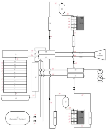
A passive safety system has been proposed for the SCWR. It is composed of PRHR heat exchanger, PRHR tank, and compensation tank. Feasibility study on the passive safety system without compensation tank had been performed4), and the results showed that the core
cooling was important just after the feedwater loss. In the present study, compensation tanks are installed at the upstream of PRHR heat exchanger to mitigate initial core heat-up. Figure 8 shows the nodalization of TASS/SCWR for the SCWR with PRHRS. The safety analysis for the current design is now in progress.
4. Conclusion
A safety analysis code TASS/SCWR has been developed for the application to a SCWR. A set of test calculations has been carried out for the developed models. Any mathematical and numerical problems are not found in the test calculation and the results of TASS/SCWR and MARS codes showed a good agreement. TASS/SCWR will be applied to the safety analysis of the SCWR with PRHRS.
Figure 8. Nodalization of TASS for SCWR 33 23 34 1 14 35 32 13 14 22 33 31 24 36 23 15 21 22 32 25 15 16 17 18 19 20 21 24 30 17 18 19 20 25 26 27 28 29 27 28 29 30 12 11 10 9 8 7 6 5 4 3 2 1 12 11 10 9 8 7 6 5 4 3 2 13 35 (Supression Chamber) 37 PRHR PRHR 31 34 (Turbine) FW FW 38 36 37 16 39 26 40 REFERENCES
[1] H. Y. Yoon et al., Thermal hydraulic model description of TASS/SMR, KAERI/TR-1835/2001, Korea Atomic Energy Research Institute, 2001.
[2] William T. Parry, James C. Bellows., John S. Gallagher and Allan H. Harvey, ASME International Steam Tables for industrial use : Based on the IAPWS International Formulation 1997 for the thermodynamic Properties of Water and Steam (IAPWS-IF97), CRTD-58, ASME, 2000.
[3] B. D. Chung et al., MARS3.0 Code manual input
requirements, KAERI/TR-2811/2004, Korea Atomic
Energy Research Institute, 2004.
[4] H. Y. Yoon and Y. Y. Bae, Feasibility Study of a Passive Safety System for a Supercritical Pressure Water Cooled Reactor, GENES4/ANP2003, Sep. 15-19, 2003, Kyoto, JAPAN. 0 20 40 60 80 100 120 140 160 180 200 12 14 16 18 20 22 24 26 PRESS(1) Pr essure ( M P a ) Time (s) 0 50 100 150 200 4200 4400 4600 4800 5000 5200 Tot a l E ner gy ( M J) Time (s) 300 350 400 450 500 150 200 250 300 350 400 450 500 F lo w R a te ( kg /s ) Time (s) 300 350 400 450 500 0 5 10 15 20 25 30 35 Temperature (C) Calculation Exact Cp S pe cif ic H e a t ( K J/ kg /K ) 0 50 100 150 200 725 730 735 740 745 750 755 760 Den si ty, k g /m 3 Time, sec. Cooling Node Outlet
MARS TASS Heatign Node Outlet
MARS TASS 0 50 100 150 200 562 564 566 568 570 572 574 576 578 580 582 584 Tem pera ture, K Time, sec. Heatign Node Outlet
MARS TASS Cooling Node Outlet
MARS TASS