Tube Plugging Criteria for the High-pressure Heaters of Ulchin NPP 3 & 4
Hyung Nam Kim, Yoo Hyun Ju, Choi Sung Nam, Jee Hong Jung, Min Woo Nam Korea Electric Power Reaearch Institute
103-16 munji-Dong, Yuseong-Gu, Daejeon, 305-380, Korea
1. Introduction
Power generation field urges nuclear power plants to reduce operating and maintaining costs to remain competitive. To reduce the cost by means of preventing the lowering thermal efficiency, the inspection of balance-of-plant heat exchanger, which was treated as not important work, becomes important. The tubing materials and tube thickness of heat exchangers in nuclear power plants are selected to withstand system temperature, pressure, and corrosion. But tubes have experienced leaks and failures and plugged based upon eddy current testing (ET) results. There are some problems for plugging the heat exchanger tubes since the criterion and its basis are not clearly described. For this reason, the criteria for the tube wall thickness are addressed in order to operate the heat exchangers in nuclear power plant without trouble during the cycle.
The feed water heater is a kind of heat exchanger which raises the temperature of water supplied from the condenser. The heat source of high-pressure heaters is the extraction steam from the high-pressure turbine and moisture separator re-heater. If the tube wall of the heater is broken, the feed water flowing inside the tube intrudes to shell side. This forces the turbine to be stop in order to protect it.
There are many codes and standards to be referred for calculating the minimum thickness of the heat exchanger tube in the designing stage. However, the codes and standards related to show the tube plugging criteria may not exist currently. In this paper, a method to establish the tube plugging criteria of BOP heat exchangers is introduced and the tube plugging criteria for the high pressure heaters of Ulchin NPP No. 3 and 4. This method relies on the similar plugging criteria used in the steam generator tubes.
2. Methods and Results
It is very hard to know the shape of the cross-section of thinned tube by conventional non-destructive testing. The thinned shape will be between the eccentric shape(Fig. 1(a) ) and the uniform shape(Fig. 1(b)). Fortunately, The stresses for the thinning ratio of the eccentric shape and uniform shape are not much different as shown by Fig. 2. In this paper, it is assumed that the thinned shape is uniform.
The steam generator tube plugging criteria depends on the USNRC Regulatory Guide 1.121, Bases for Plugging Degraded PWR Steam Generator Tubes. The Guide 1.121 says the following factors should be
considered: 1) the minimum tube wall thickness needed for tubes with defects to sustain the imposed loading under normal and accident conditions, 2) between the inspections, the allowance of degradation, 3) the crack size permitted to meet the leakage limit allowed per the technical specification. The last one is not clearly needed for the tubes of the BOP heat exchangers.
As shown by previous paragraph, the Guide treats two conditions, the normal operational condition and the accident condition. The basis of the judgement for the steam generator tube integrity is the safety factors mentioned in ASME Sec. III. The requirements for the tube to be satisfied for the normal operational condition are the same as the general machine design. Therefore, it is convenient to apply the Guide directly to the BOP heat exchanger. In this paper the maximum stress due to the normal operation condition and thermal gradient is calculated. Then the stress with the safety factors mentioned in ASME Sec. III is compared with the yield strength and tensile strength of tube material at the appropriate temperatures in order to establish the required tube wall thickness. The material properties are given by ASME Sec. II Part D.
The requirements of the Guide for the accident condition are connected with two postulated accidents. They are the steam line break and loss of coolant accidents(LOCA). While the first one can be applicable to establish the tube plugging criteria of the BOP heat exchangers, the second one can not. For considering the first accident condition, the maximum stress due to the design pressure without shell-side pressure is calculated. Then the stress with the safety factors mentioned in ASME Sec. III is compared with the yield and tensile strength of tube material at the design temperatures in order to establish the required tube wall thickness. The LOCA condition can not be considered directly to the heaters. The steam generator tubes are supposed to be pressed by outside pressure during the LOCA. Observing this fact, the similar condition is adopted for the tubes of heaters in this paper. The minimum wall thickness required for this condition is calculated using the well-known formula.
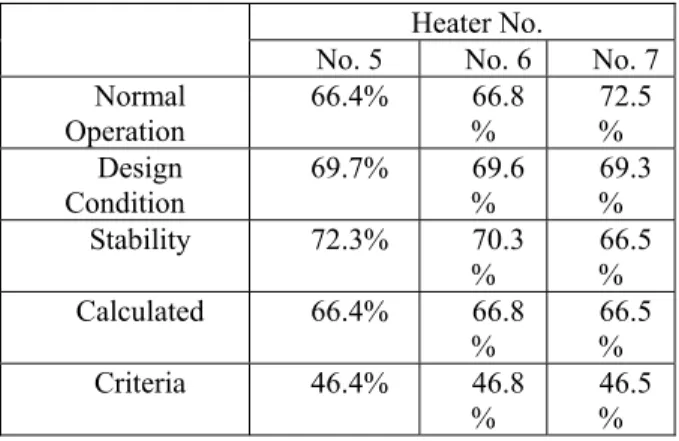
The plugging criteria should include factors for increase in the flaw size between the inspection, which is normally 10% of the installed wall thickness, and for the NDT error, which is also 10% of the installed wall thickness. Including these factors, The tube plugging criteria of the HP feed water heaters of Ulchin NPP No. 3 and 4 are established as in Table 1.
Transactions of the Korean Nuclear Society Autumn Meeting Busan, Korea, October 27-28, 2005
Figure 1. Thinned shapes (a) eccentric, (b) uniform
Figure 2. Stresses in the tube with the eccentric and uniform cross-section for the thinning ratio
Figure 3. Minimum wall thickness required for the HP heater No. 5 of Ulchin NPP No. 3 & 4 at normal operation.
Figure 4. Minimum wall thickness required for the HP heater No. 6 of Ulchin NPP No. 3 & 4 at normal operation.
Figure 4. Minimum wall thickness required for the HP heater No. 6 of Ulchin NPP No. 3 & 4 at normal operation.
Table 1. Plugging criteria for the HP heater No. 5, 6 and 7 of Ulchin NPP No. 3 & 4
Heater No.
No. 5 No. 6 No. 7 Normal Operation 66.4% 66.8 % 72.5 % Design Condition 69.7% 69.6 % 69.3 % Stability 72.3% 70.3 % % 66.5 Calculated 66.4% 66.8 % % 66.5 Criteria 46.4% 46.8 % 46.5 % 3. Conclusion
A method to establish the tube plugging criteria of BOP heat exchangers is introduced and the tube plugging criteria for the high pressure heaters of Ulchin NPP No. 3 and 4. This method relies on the similar plugging criteria used in the steam generator tubes. The tube plugging criteria of the HP feed water heaters of Ulchin unit 3 and 4 are provided.
REFERENCES
[1] A. C. Ugral, Stresses in Plates and Shells, McGraw Hills, Inc., 1981.
[2] S. P. Timoshenko and J. N. Goodier, Theory of Elasticity, McGraw Hills, Inc., 3rd Ed., 1970.
[3] C. H. Kent, Thermal Stresses in Thin-Walled Cylinders, Trans. Of ASME, Vol. 53, pp.167-180, 1931.
[4] E. U. Schlunder, Editor-in-chief, Heat Exchanger Design Handbook Vol. 4(Mechanical Design of Heat Exchanger), Hemisphere Publishing Corp., p. 25, 1983.
[5] K. Krzywosz, EPRI Condition Assessment and Inspection Program for Reducing Heat Exchanger Tube Leak, Proceedings of 6th EPRI Balance-of-Plant Heat Exchanger
NDE Symposium, 2000. Thinning (%) 55 60 65 70 75 80 M ax . S tr ess In te ns it y ( ks i) 0 5 10 15 20 25 30 35 18.8ksi (Sy of SA-688 TP304L at 316.7 oF) 66.4% 21.1ksi (Su /3 of SA-688 TP304L at 316.7 oF) 67.6% Thinning (%) 55 60 65 70 75 80 M ax . S tr ess In te ns it y ( ks i) 0 5 10 15 20 25 30 35 17.8ksi (Sy of SA-688 TP304L at 375.9oF) 66.8% 19.6ksi (Su /3 of SA-688 TP304L at 375.8oF) 70.4% Thinning (%) 55 60 65 70 75 80 Max. St res s Int ensi ty ( ksi ) 0 5 10 15 20 25 30 35 17.1ksi (Sy of SA-688 TP304L at 429.9 oF) 72.5% 19.4ksi (Su /3 of SA-688 TP304L at 429.9oF) 76.4%