1. INTRODUCTION
Recently the ubiquitous computing which can communicate with the human in anywhere without the user’s reorganization of the system, has been noticed as the new paradigm of computerization. In the ubiquitous environments, the computer needs to obtain user’s intention or information with accuracy. For this reason, the Human Computer Interaction (HCI) has occupied an important position.
Over the past year, many sensing modalities have been introduced for HCI such as keyboard, mouse, and haptic device. Although they can acquire user’s intention with accuracy, they have to equip certain device on human’s body or need the skill to control them. This is not sufficient to satisfy those requirements of HCI for ubiquitous computing. At this point, one of the effective sensing modalities that make user’s effort become minimized is the vision system for HCI because it uses cameras which are typical passive sensor and it has reliable performances. However, it has also the demerit of the computer vision such as considerable amount of image processing [1] and dynamic illumination problem. To overcome these problems, many researches have been proposed.
In vision-based HCI, there are many perception modalities. These can be divided into six categories such as [2]: people tracking, gesture recognition, facial perception, facial expression, eye orientation tracking and head pose tracking. Especially, the head pose tracking has a unique advantage that it is the simple and general approach to obtain user’s geometrical attention. A direction of attention is an intuitive pointing cue for estimating user’s intention. We can simply obtain user’s intention by estimating the head pose. Therefore, the estimating of head pose is simple way to obtain user’s intention.
Many of the previous researches were proposed on this topic. Yang [3], Liang [4] and Haville [5] have developed an optical flow method in which the head pose is tracked by analyzing the change of features between the image frame sequences. However, their methods need the manual feature initialization and they have boost-trapping problem which require several frames to estimating correct data when the typical optical flow system starts. Yang [6] used a skin color as a visual feature of their system. This method might not cover
the bad illuminative condition because they used the general mono-camera which has a limitation to detect color feature under the bad illuminative condition.
To deal with these problems, we proposed the new algorithm of human head pose estimation in this paper. The main idea of our approach is to suggest a new morphological feature for estimating head angle from the constrained stereo camera disparity map. When a disparity map obtained from stereo camera, the matching confidence value, which is derived from the measurements of correlation of the stereo images, can be obtained. By applying the threshold to the confidence value, we can obtain the morphological shape of disparity map. Through the analysis of this morphological property, the head pose can be estimated.
This approach can perform automatically without manual feature initialization and boost-trapping problem. The disparity map is relatively robust against illumination changes because the disparity can be estimated from the matching of stereo frame pair. Additionally, our algorithm can be computed in real time.
The remainder of the paper is organized as follows: In section 2, our algorithm is presented. First, we describe preprocessing procedure before our algorithm work. Second, the main feature is introduced and explained how to acquire. Then third, we explain head segmentation algorithm from background. Forth, the head pose estimation algorithm is described. In section 3, we cover the system setup with detail specification. In section 4, we show the experimental result of our system. And finally in section 5, we evaluate our algorithm and conclude this paper.
2. HEAD POSE ESTIMATION
In this section, we propose the entire procedure which estimates head rotation parameter. We suggest the key feature and explain the procedure of our method.
Our head pose estimation process is classified into the following seven steps in detail like Fig. 1. In the step 1, calibration for stereo camera is implemented. And then, the morphological feature from constrained disparity map is explained in the step 2. The head segmentation from background and head pose estimation process are performed in the step 3-4 and 5-7, respectively. Figure 1 shows a quick
Head Pose Estimation by using Morphological Property of Disparity Map
Sewoong Jun*, Sung-Kee Park* and Moonkey Lee**
*Intelligent Robotics Research Center, Korea Institute Science and Technology, Seoul, Korea (Tel : +82-2-958-6744; E-mail: {smokey,skee}@kist.re.kr)
**Department of Electrical & Electronic Engineering, Yonsei University, Seoul, Korea (Tel : +81-2-2123-2867; E-mail: [email protected])
Abstract: This paper presents a new system to estimate the head pose of human in interactive indoor environment that has
dynamic illumination change and large working space. The main idea of this system is to suggest a new morphological feature for estimating head angle from stereo disparity map. When a disparity map is obtained from stereo camera, the matching confidence value can be derived by measurements of correlation of the stereo images. Applying a threshold to the confidence value, we also obtain the specific morphology of the disparity map. Therefore, we can obtain the morphological shape of disparity map. Through the analysis of this morphological property, the head pose can be estimated. It is simple and fast algorithm in comparison with other algorithm which apply facial template, 2D, 3D models and optical flow method. Our system can automatically segment and estimate head pose in a wide range of head motion without manual initialization like other optical flow system. As the result of experiments, we obtained the reliable head orientation data under the real-time performance.
overview of the algorithm.
Fig. 1 Head Pose estimation algorithm sequences
2.1 Camera calibration
To obtain precision disparity map, we need a fine camera calibration. An accurate intrinsic and extrinsic camera parameter is essential for the disparity matching procedure. In this paper, we used the commercialized library, which is Smallvcal and VidereDesign’s camera calibration program [7, 9].
2.2 Obtaining Morphological feature
Obviously, accurate disparity map is one of the essential factors for our stereo camera based head pose estimation system. We use Videre Design SVS library [8] to estimate the disparity map on real-time. It adopts the texture property to reduce errors of the disparity. In general, the result of stereo matching contains incorrect matches. One of the major sources for the errors is lack of sufficient image texture. Thus, Videre Design SVS library also employs the texture property of image as an error filter and it can be applied for the measuring the correlation of stereo images.
When we apply the threshold to the measurement of correlation, we can obtain the disparity map that satisfies some confidence of stereo image matching. Simply, the threshold value can be the matching confidence about correlation. It means the representative value how correctly match the two images of the stereo cameras. And, it has a characteristic that complex texture has a high confidence value on the stereo images. Since the confidence value is based on image textureness, we can obtain a constrained disparity map which contain only high texture region by applying the high matching confidence value as a threshold to the original disparity map.
However, through the observation of the disparity map, we could find a new meaning of reliable disparity map which
original disparity map. It has not only the depth information but also some morphological property about human posture. In the human head and face, eyes, nose and mouse have a complex texture compare with other parts like hair, forehead and checks.
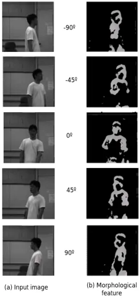
Fig. 2 shows the morphological feature which obtained from constrained disparity map that emphasizes eyes, nose and mouse of human face. And, the morphological feature has an invariant property for yaw head rotation when the human face can be shown by the camera.
(a) Input image (b) Morphological feature -90º -45º 45º 90º 0º
Fig. 2 (a) shows input image from left camera and (b) represents morphological feature from constrained disparity
map individually on various yaw head pose of human We focus on our research to this property. The morphological feature from the constrained disparity map is a main key of our head pose estimation algorithm. We obtain the constrained disparity from the SVS library when our head pose estimation algorithm starts. Then, the morphological feature is calculated by making all constrained disparity as same value. The detail will be described following section.
2.3 Head segmentation
The task of head segmentation from the background is an important key to obtain accurate head pose parameter. In our system, we implemented a head detecting algorithm under the complex background and dynamic variation of illuminative condition.
A Stereo sequence offers the powerful method for segmenting images for application such as tracking human figure. Tracking, which uses range information, presents fewer problems compare with template matching approach or contour model approach. The stereo video is relatively unaffected by lightning condition in an extraneous motion [10].
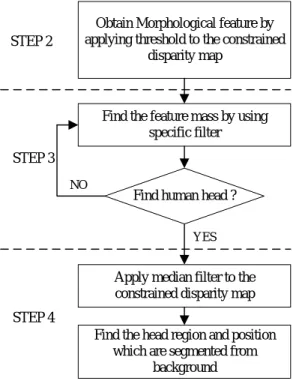
Partially, our head segmentation algorithm adopts Eveland approach [10]. He introduced the background segmentation method by using static stereo image. However, we optimize this idea for one person who locates in the working space and obtained better result. Our head segmenting algorithm is achieved following three steps that shows on Fig. 3 and describes below.
Obtain Morphological feature by applying threshold to the constrained
disparity map
Apply median filter to the constrained disparity map Find the feature mass by using
specific filter
Find human head ?
Find the head region and position which are segmented from
background NO YES STEP 2 STEP 3 STEP 4
Fig. 3 head segmentation algorithm
First, in step 2, we compute the morphological feature from the constrained disparity map which mentioned previous section 2.2. The morphological feature is a map which contains only 2D information. Thus, it reduces the computational complexity compare with 3D constrained disparity map. The equation of morphological feature can be written as follows: ⎩ ⎨ ⎧ > = otherwise 0 1 if d conf M (1)
where M is the morphological feature and d is the constrained disparity map, and conf is the matching
confidence value.
Second, from the step 3, we find a feature mass which assume that human head in the morphological feature by using specific filter on every pixel of morphological feature. The filter is designed to find that whether there are other pixels or not on its neighbors. If there are a few neighbor pixels around the filtered pixel, the pixel should be noise and will be reduced on the morphological feature map. The scanning procedure starts with left top corner and it finishes when it finds the human head.
Finally, in the step 4, to obtain the reliable head region, we use a median filter to the depth value which can be obtained from constrained disparity map. And then, the head region size is calculated easily from the depth value because the size of head depends on the distance form the camera.
From the above steps, we obtain accurate head position and head range so that we could estimate head pose estimation which suggests next section.
2.4 Head pose estimation
Head pose orientation can be specified into tree rotational parameters: Roll, Pitch, Yaw. Among these parameters, Yaw is the most important key in the aspect of typical human behaviors [11].
Therefore, we founded that an aspect of morphology feature map has an invariant property for the head yaw rotation parameter that mentioned before on section 2.3. This morphological feature distribution can be analyzed by morphological approach.
We suggest our head pose estimation algorithm. Fig. 4 shows it simply and the algorithm is explained in detail in the following paragraphs.
Fig. 4 head pose estimation algorithm
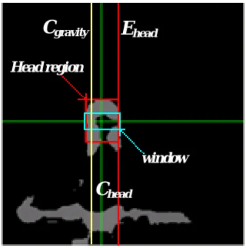
First of all, in the step 5, we set a rectangular window to the center of the head morphological feature region that obtains from previous work in section 2.3. Fig. 5 shows the window and its size also depends on the size of head region.
Second, from the step 6, a COG (center of gravity which assume that every pixels in the morphological feature map has same weight) of the morphologicalfeature in the window is calculated by following equation.
( )
∑
= = N j i ij gravity avr W C 1 , (2)where Cgravity is the COG of the window, W is each pixel ij
of morphological feature map in the window and N
represents a number of pixel of all W respectively. ij
Finally, in the step 7, as the end of this algorithm, we calculate the human head yaw parameter by applying COG on the center and edge of head region. Fig. 5 shows these parameters. This can be formulated as following.
head head head gravity yaw C E C C s H − − = (3)
where Chead is a horizontally center position value of
head region, Ehead is a horizontally edge position value of
head region, s is a scale factor and the result Hyaw
represents the head yaw angle of human.
E
headC
gravityC
headwindow Head region
Fig. 5 parameters for head pose estimation
3. EXPERIMENTAL SETUP
We implement our algorithm using C++ under the Pentium 4 PC with Microsoft Windows environment and the Videre Design MEGA-D stereo camera is connected by IEEE1394 cable. We use the Videre Design SVS library to estimate the disparity map on real-time (about 24 frames per second at 320x240 frame resolutions). The camera is fixed vertically on the wall of our experimental studio where is placed in one of the rooms at Korea Institute of Science and Technology. The camera is hanged at 180cm height from the ground. We set up the system which consists of vertically arranged stereo camera because it provides higher disambiguation power in stereo feature matching. Matching ambiguity usually involves facial features such as eye and lib contours aligned horizontally [3]. The experimental studio has a complex background and it can control the illumination condition by using 8 fluorescent lamps. The working space has a size which is 6m x 6m x 3m so that the studio could cover every field of camera views (each camera has a lens of 6mm focal length).
Fig. 6 shows the overview of our system setup. One person can be located in the studio. He or she can stand wearing any clothe and move any anywhere within working space. The stereo camera was calibrated previously before the system starting.
Fig. 6 The system overview and experimental studio with the complex background and illumination condition
4. EXPERIMENTAL RESULT
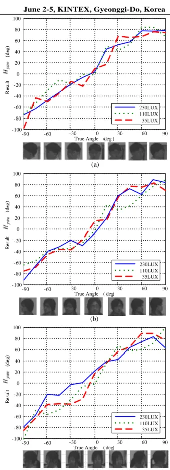
To obtain better experimental result, we used several human models that have different appearance in face color, hair style and gender. And target human’s head was fixed against roll and pitch rotational parameters. This makes that we measure only yaw parameter steadily. We collected head pose data that ranged from -90º to 90º for various model appearances and under the different lightning condition.
Fig. 7 shows the result of yaw head pose estimation of different type models and lightning conditions. Our experiments result was acquired from 3 different models that have a dark skin color and short hair style, middle bright skin color and middle long hair style and bright skin color and long hair style model. All experiments were performed under the 3 different illumination conditions which consist with bright indoor light (230 Lux), middle bright light (110Lux) and dark illuminating conditions (35 Lux).
As the result of experiments, we obtained the robust orientation parameters against the variation of illumination condition and the appearance of different types. All data could obtain in the real-time (24frames/sec).
5. CONCLUSION
In this paper, we suggested a new approach of estimating head pose by analyzing morphological feature from the constrained disparity map which is derived from the measure of correlation of the stereo image. When a disparity map obtained from stereo camera, the matching confidence value, which is derived from the measurements of correlation of the stereo images, can be obtained. Applying a threshold to the confidence value, we also obtain the specific morphology of the disparity map. Therefore, we can obtain the morphological shape of disparity map. Through the analysis of this morphological property, the head pose can be estimated.
We show that the experimental result under the different lightning condition and different models. And, we could obtain reliable results. As shown in the experimental results, we showed that our algorithm can be robust against changes of illumination condition and differences of human head appearance. It also has wide working space because we adopted head segmentation method which can extract head in the entire field of view. Additionally, our approach is not based on optical flow. Therefore, it does not require the manual initialization and there is no boost trapping problem.
modality of the future ubiquitous and intelligent environments which require all above conditions in the real time performance.
REFERENCES
[1] E. Trucco and A. Verri, Introductory Techniques for 3-D Computer Vision, Prentice Hall, New Jersey, 1998.
[2] T. Fong, I. Nourbakhsh and K. Dautenhahn, “A survey of socially interactive robots,” Robotics and Autonomous Systems, 42:143-166, 2003.
[3] R. Yang and Z. Zhang, “Model-based head pose taking with stereovision,” Technical Report, MSR-TR-2001,
2001.
[4] G. Liang, H. Zha and H. Liu, “Affine correspondence based head pose estimation for a sequence of images by using a 3D model,” IEEE International Conf. on Automatic Face and Gesture Recognition, Seoul, Korea,
2004.
[5] M. Harville, A. Rahimi, T. Darrell, G. Gordon and J. Woodfill, “3D Pose Tracking with Linear Depth and Brightness Constraints,” Proc. of the IEEE ICCV., Conf, Greece, 1999.
[6] J. Yang, R. Stiefelhagen, U. Meier, and A. Waibel, “Real-time face and facial feature tracking and applications,” in Proc. of AVSP’98, pp 79-84, Terrigal,
Australia, 1998.
[7] K. Konolige and David Beymer, SRI Small Vision System: Calibration Addendum to the User’s Manual Software version 3.2g, Videre Design, November 2004.
[8] K. Konolige and David Beymer, SRI Small Vision System: User’s Manual Software version 3.2g, Videre
Design, November 2004.
[9] R. Tsai, “A versatile camera calibration technique for high-accuracy 3D machine vision metrology using off-the-shelf TV camera and lenses,” IEEE Journal of Robotics and automation, Vol. RA-3, No. 4, 1987.
[10] Eveland, C., K. Konolige, and R. C. Bolles, ” Background modeling for segmentation of video-rate stereo sequences,” Conference on Computer Vision and Pattern Recognition, Santa Barbara, CA (June 1998).
[11] M. Romero, A. Bobick, “Tracking head yaw by interpolation of template responses,” Conf. Computer Vision and Pattern Recognition Workshop (CVPRW’04),Vol. 5, 2004.
[12] P. Viola and M. Jones, “Rapid Object Detection using a boosted cascade of simple features,” IEEE Computer Society on Computer Vision and Pattern Recognition (CVPR), ISSN: 1063-6919, Vol. 1, pp. 551-518,
December 2001.
[13] E. Seemann, K. Nickel, and R. Stiefelhagen, “Head pose estimation using stereo vision for human-robot interaction,” Proc IEEE International Conference on Automatic Face and Gesture Recognition, pp. 626-631,
2004.
[14] Y. Wei, L. Fradet, and T. Tan, “Head Pose estimation using gabor eigenspace modeling,” Proc.International Conference on Image Processing, Vol 1. pp. 281-284,
2002.
[15] D. Decarlo and D. Metaxas, “Optical flow Constraints on deformable models with application to face tracking,”
IJCV, 38(2):99-127, July, 2001 -60 -30 0 30 60 -100 -80 -60 -40 -20 0 20 40 60 80 100
True Angle ( deg)
-90 90 -60 -30 0 30 60 -100 -80 -60 -40 -20 0 20 40 60 80 100
True Angle ( deg)
-90 90 (b) (c) -60 -30 0 30 60 -100 -80 -60 -40 -20 0 20 40 60 80 100
True Angle (deg )
-90 90 (a) 230LUX 110LUX 35LUX 230LUX 110LUX 35LUX 230LUX 110LUX 35LUX
Fig. 7 Head Yaw Estimation in the different appearance human and under the different lightning condition (a) dark skin color and short hair style model (b) middle skin color and middle long hair style model (c) bright skin color and long hair style model