1. INTRODUCTION
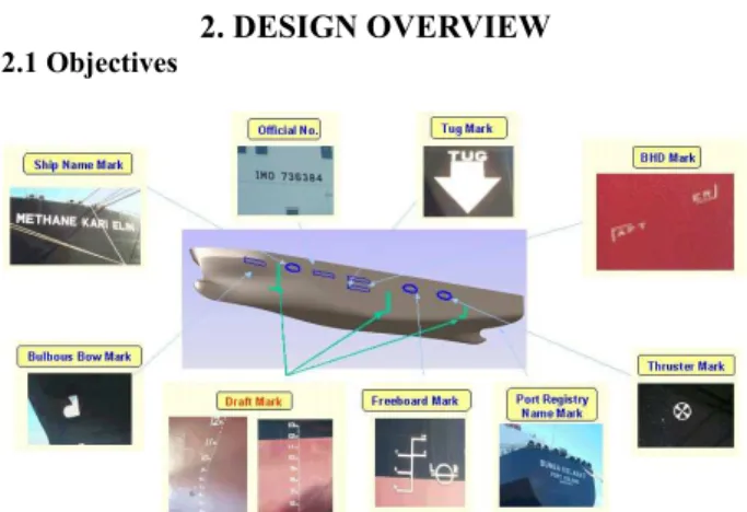
Ships have marks of various shapes on outside of the hull. For example, they are Ship Name Mark, Official No., Tug Mark, BHD Mark, Thruster Mark, Freeboard Mark, Bulbous Bow Mark etc. Among them, so called “Draft Mark” indicates the distance from the bottom of the keel to the waterline. Draft Marks are used to determine the displacement and other properties of the ship for stability and control purposes. Usually, these marks are made up of welding bead or sticking the steel plate on outside of the hull. To improve the confidence level of the ship owner, quality and accuracy of the draft mark is very important.
However, there is trouble to manually weld the mark. In case of outdoor job, curved surface does not allow workers to access easily to that and it is difficult to carry welding instruments to the marking points though it is not impossible. In case of indoor job, expensive instrument like NC machine could be used. But, it is unnecessary to equip NC machine for only mark welding.
To cope with those situations, the automatic mark welding robot is developed [6][7][8]. That enables the high quality and accurate welding of mark shape in manufacturing line and has portability. We have developed two types of robots called SR-MARK-I and SR-MARK-II, respectively.
SR-MARK-I is developed to apply to the flat surface in indoor manufacturing process and SR-MARK-II is the system for the curved surface in outdoor manufacturing process.
Because of poor surroundings like dust, irregular producing process in shipbuilding industries, the system is required to have portability, robustness and mobility. So to improve the system portability, the system is divided into two distinct parts, namely mechanical part and control part. Mechanical part is robust, a lightweight, and easy to dismantle. The control part consists of an in-house developed controller, which is based on
embedded Linux.
SR-MARK-I is mainly focused on accuracy and high speed in indoor manufacturing process. So it has two robots on one rail and two robots are simultaneously operated. Also, the control part consists of in-house developed PLC (power line communication) module to ensure the applicability of the controller in indoor manufacturing line.
Moreover, SR-MARK-II should not only be light but also have high force-to-weight ratio so that it may reduce excessive adhesion forces during welding job. So it is designed to have robust and compact mechanism. To apply to outdoor process, we cared much about the influence of heat, water, dust, and shock during operation.
This paper is organized as follows. Section 2 describes the backgrounds and system configuration. Section 3 describes the software implementation of SR-MARK-I and SR-MARK-II in detail. In section 4 and 5, we mentioned methodologies of control and how to interface CAD data. And we concluded with summary in section 6.
2. DESIGN OVERVIEW 2.1 Objectives
Fig. 1. Marks on outside of the hull
Development of Automatic Mark Welding Robot
Sin-Wook, Ryu* , Ho-Gu Kim*, Jae-Chang Lee* and Se-hwan Kim*** Automation Research Part, Samsung Heavy Industries Co. Ltd. Geoje Shipyard 530, Jangpyeong-ri, Sinheon-eup, Geoje-city, Gyeongnam, Korea (Tel : 82-55-630-6282, Fax : 82-55-630-5562, E-mail:[email protected])
** Automation Research Part, Samsung Heavy Industries Co. Ltd. Geoje Shipyard 530, Jangpyeong-ri, Sinheon-eup, Geoje-city, Gyeongnam, Korea (Tel : 82-55-630-4700, Fax : 82-55-630-5562, E-mail:[email protected])
Abstract: Generally, ships have marks of various shapes on outside of the hull. Among them, so called “Draft Mark” indicates the distance from the bottom of the keel to the waterline. Draft marks are used to determine the displacement and other properties of the ship for stability and control purposes. These marks are made up of welding bead or sticking the steel plate on outside of the hull. To improve the confidence level of the ship owner, quality and accuracy of the draft mark is very important. So the automatic mark welding robot is used to enable a high quality and accurate manufacturing line. To improve the system portability, the system is divided into two distinct parts, namely mechanical part and control part. Mechanical part is robust, a lightweight, and easy to dismantle. The control part consists of an in-house developed controller, which is based on embedded Linux. Also, the control part consists of power line communication module to ensure the applicability of the controller in manufacturing line. In this paper, the methodologies of control and configuration of the robot are discussed.
Among the marks on outside of the hull in Fig.1, accuracy of “Draft Mark” is very important, because they are used to determine the displacement and other properties of the ship for stability and control purposes. So ship owner is sensitive about quality and accuracy of the draft mark.
However, because of poor work surroundings and troublesome process, manual mark welding requires many hours and manpower.
So, We proposed two types of the portable mark welding robots. One enables high speed and accurate welding of mark shape. And another enables accurate welding regardless of angle and shape of surface.
2.2 Specification SR-MARK-I
As shown in Fig.2, the structure of SR-MARK-I is divided into two distinct parts, namely mechanical part and control part. And that includes welding instruments, also. Considering two Cartesian robots in one rail with 2m in size, that is relatively light with about 42kg. The welding speed is very high as about 1.5m/min.
Fig. 2. Layout of SR-MARK-I
It is composed of two Cartesian robots and control system. The controller controls two SCR (Silicon Controlled Rectifiers) type welding machines and robots relatively like Fig.2.
Fig.3 shows that SR-MARK-I is welding draft mark to the flat surface. End effecter of robot is end point of welding torch.
Fig. 3. SR-MARK-I
The control system is composed of an in-house developed embedded controller with PC104 bus that integrates A/D converter, several DIO channels and including designed motion control board and motor driver board by 8 axes.
In order to transmit the data including the position
information of character, the control system consists of in-house developed power line communication (PLC) module. The data rate of PLC module is 14 Mbps.
SR-MARK-II
SR-MARK-II, handling supporter and welding instruments are mounted in large-sized crane, as shown as Fig.4.
Fig. 4. Layout of SR-MARK-II
The basic structure of SR-MARK-II is similar to SR-MARK-I. Only Suction pad is added at the lower part of robot. That is divided into two parts similarly. It is relatively small in size with 1m, and 20kg in weight. The welding speed is 1.3m/min, also.
The structure of control system is nearly similar to previous version. But pneumatic control part including air filter, regulator, solenoid valve, vacuum generator and pressure sensor etc. is just added.
Fig.5 shows that SR-MARK-II is welding draft mark to the curved surface in vertical position.
Fig. 5. SR-MARK-II
It consists of a Cartesian robot and control system. The controller controls inverter type welding machine, pneumatic cylinder, suction pad, and robot. Because welding condition is very sensitive related to posture of robot in applying to the curved surface, high priced inverter type welding machine is selected. Also, the system includes inclinometer inside robot, so welding condition can be controlled by posture of robot.
Since it can sense welding current by Hall sensor mounted in wire feeder, Z-axis is controlled to maintain equal height that make welding current regular. The control method like that is called arc sensing. In section 4, it will be explained in more detail.
3. SOFTWARE IMPLEMENTATION
3.1 The Structure of Software SR-MARK-I
Fig.6 shows the structure of low-level software inside controller. We adopted RT-Linux to realize the synchronized control of two robots.
Fig. 6. Software structure of SR-MARK-I
In more detail, main thread is located in the middle and 4 sub-threads are spread around main thread. Each sub-thread has a important role. They are generating continuous path motion of robot1 and robot2, treating pendant signal, and watching emergency state etc. Main thread includes the functions that play a role in saving teaching point, jog motion, and I/O control etc.
SR-MARK-II
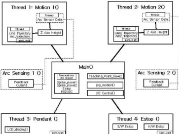
Fig.7 shows the structure of low-level software inside the controller of SR-MARK-II.
Fig. 7. Software structure of SR-MARK-II
Similarly, main thread is located in the middle and 4
sub-threads are spread around main thread. Each sub-thread is the thread for generating continuous path motion of robot, treating pendant signal, watching emergency state, and arc sensing etc.
Main thread includes the important functions. They are for saving teaching point, jog motion, I/O control, welding condition control, and data transformation etc.
3.2 Functionality Description Continuous Path Motion
The capacity of continuous path motion is very important to make high quality welding bead. As the trajectory is varied, the acceleration and deceleration period has to be minimized. If it were not minimized, the welding bead would show the result of that immediately.
We implement the continuous path motion that minimizes the acceleration and deceleration period [1,2,9-13]. The trajectory is optimized to prevent the robot from jerk by every character, also. And the controller calculates the velocity of each axis to reach next position on the trajectory at 1msec intervals using real-time PD control.
Synchronizing
Usually, main thread is a signal handler including system timer, while all other threads block signals. Sub-threads run in a loop, waiting for semaphore to be released to process signal. When sub-threads get semaphore from main thread, it can keep its important operation. So all threads can be processed synchronously.
We used the POSIX based semaphore and pthread supported by RT-Linux compiler. These were used for coordinating and synchronizing activities in which multiple threads compete for the same operating system resources.
4. CONTROL METHOD
4.1 Tracing curved surface
The front and rear part of a ship, that is, the bows and stern has large curvature for the purpose of smooth progression of a ship regardless of the influence of fluid pressure. The shape of curved surface is determined by drawing. But it is very difficult to precisely manufacture the curved surface according to drawing.
We cannot know about curvature information of the curved surface. So it cannot be resolved by kinematical calculation and the ability of tracing the unknown curved surface is inevitably required. Because the performance of tracing determines the quality of welding bead, it is very important at the aspects of the overall performance, also.
Also, because original position information of character is based to flat plane and it is impossible to align the robot to the curved surface, data transformation is inevitably required. Arc Sensing
current. Then we use the tendency to calculate position of Z-axis to maintain the current value.
However, Welding current data is originally very unstable like Fig.8 (a). To get reliable tendency for current data to vary, Kalman filtering was adopted [14-16]. This filter is designed for data estimation. Fig.8 (b) shows the result of filtering through calibrating the parameter of filter.
The parameter of filter is the important factor related to welding quality. By using Kalman filter, we got welding bead of high quality regardless of shape of surface.
(a) (b)
Fig. 8. Result of welding current filtering (a) Raw data, (b) Filtered data Data Transformation
As mentioned above, it is impossible to align the robot to the curved surface, because suction pad is fixed whereas the curvature of surface is various. By teaching XYZ position of three points on the outer line, we transformed the position data of character into new coordinate in the based of robot. Laser diode is located beside the welding torch, and worker performs the teaching job with looking at laser diode.
Fig. 9 shows the definition of coordinates. Transform Matrix has to describe the frame B at the base of the character relative to the base of the robot. So the matrix rotates and translates frame B relative to frame A [3].
Fig. 9. Coordinate transformation
In Fig. 9, blue points P1, P2, P3 are teaching points on the outer line and each point has XYZ position data.
Rotation matrix is equivalent to
∧ ∧ ∧ ∧ ∧ ∧ = = T A B T A B T A B B A B A B A A B Z Y X Z Y X R
(1)
Assume that rotate data about X-axis by an angle theta1, rotate data about Y-axis by an angle theta 2, rotate data about Z-axis by an angle theta 3, and translate the amount of difference between the base of robot and the base of character in X, Y direction,
The transform matrix is equivalent to
2 3 1 2 3 1 3 1 2 3 1 3 _ 2 3 1 2 3 1 3 1 2 3 1 3 _ 2 1 2 1 2 0 0 0 0 1 1 1 A B A B A B C C S S C C S C S C S S Teach x offset x x C S S S S C C C S S S C Teach y offset y y S S C C C z z − + − + − − = −
(2)
The result of Eq. (2) is as follows.
2 3 ( 1 2 3 1 3) ( 1 2 3 1 3) A B B B x =C C X + S S C −C S y + C S C +S S z
(
Teach x offset
_
)
+
−
(3)
2 3 ( 1 2 3 1 3) ( 1 2 3 1 3) A B B B y =C S X + S S S +C C y + C S S −S C z (Teach_y offset) + −(4)
2 1 2 1 2 A B B B z = −S x +S C y +C C z(5)
Where, offset means the difference between the center of torch and the center of laser diode.
Eq. (3), (4), and (5) determines the trajectory of the end of torch. But Eq. (5) was not practically used, because the trajectory of Z-axis is determined by arc sensing.
4.2 Welding Condition Control
Fig. 10. Test bed for welding condition by angles Welding condition is originally sensitive to the angle of surface and torch. To cope with the various angle of surface in the front and rear part of a ship, we tested the welding
condition with the bead of high quality by every angle previously. For the test, test bed as shown in Fig. 10 is used. And the all exterior of robot is covered with aluminum cover and asbestos fiber.
From the result of welding condition test, qualified welding parameter was divided into four cases by angles. But selecting the welding machine, the length of ground cable and power cable, and the stability of power source etc. could change that condition.
Inclinometer is located in the center of robot. The controller can know about the present inclination. So robot can call the optimized welding condition at the present inclination.
Fig. 11 Result of welding test
Fig. 11 shows the result of qualified welding bead. Really the shape of welding bead is slightly different by every angle. But we tried to make the bead equal regardless of inclination.
5. CAD DATA INTERFACE
5.1 CAD Data Conversion
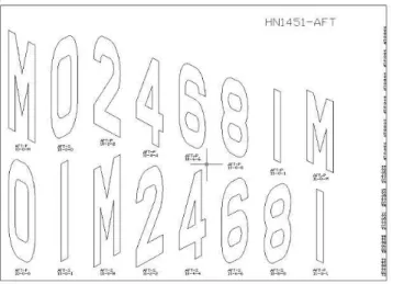
In case of flat plain, Original position information of character is based on NC code. And data of curved surface is extracted from AutoCAD drawing. These conversions are performed by upper-level CAD interface software, so called data file generation program. Fig. 12 shows original drawing of characters in curved surface [4][5]. As shown in Figure, all distorted characters are shown a correct letter, when they are projected to the vertical surface.
Fig. 12. CAD data in curved surface
Data file generation program has graphical user interface
like Fig. 13. This program is installed in field office. Firstly a worker copies the NC data or CAD drawing from CAD server through the intranet and select the appropriate data. A worker can confirm the data graphically and then data file is generated.
Fig. 13. GUI of CAD data interface software 5.2 Data Transmission
Fig. 14 shows the flow of data. Firstly, original data in CAD server is transmitted to field office in the form of NC code and CAD drawing through intranet. So data file generation program convert original data into data file format that can be recognized by robot controller.
This data is stored in specific directory and then socket server program starts to wait for the connection through the specific port number. The robot controller connects to server in the field office and downloads the appropriate data file through power line communication or floppy disk.
6. CONCLUSION
The proposed systems are two types of the mark welding robots, called SR-MARK-I and SR-MARK-II. First system has been proved to be a high speed and accurate mark welding robot. And another has been proved to enable stable adsorption outside the hull and accurate welding regardless of angle and shape of surface.
In point of fact, it can be said that the main techniques for applying the robot to the field was robust mechanical design suitable for field environment, the design of adsorption part, calibrating arc sensor, coordinate transformation, implement the continuous path motion, and CAD data interface etc.
Finally, we succeed in stabilization these techniques and realize the automation of mark welding using SR-MARK series. Now, we are planning to apply the robots to other marks outside the hull.
ACKNOWLEDGMENTS
The authors are grateful for the support provided by a grant from Samsung Heavy Industries.
REFERENCES
[1] Hu-min Huang, et all, "A Motion Control Algorithm for a Continuous Mining Machine Based on a Hierarchical Real-Time Control System Design Methodology", National Institute of Standards and Technology Gaithersburg, 1991.5
[2] HaiJun Su, et all, "Trajectory Planning for Constrained Parallel Manipulators", UCI, August, 2002
[3] Tsuneo Yoshikawa, Foundation of Robotics Analysis and Control, 1990, MIT Press
[4] 115,000 DWT CRUDE OIL TANKER, DRAFT MAR ARRANGEMENT No. 220 DF 002.30, 2003.12
[5] 145,000 M3 LNG CARRIER, DRAFT MARK ARRANGEMENT No. 220 DF 002.30, 2004.9
[6] KR 2001-0027904, Yu-Jae Park, Draft Mark Welding Machine for ship, 1999.9.16
[7] KR 2000-0055999, TAK SEUNG-HO, Level and vertical line indicator using laser beams, 2004.1.5 [8] JP 1999-229018, MURAKAMI KOJI, AUTOMATIC
WELD CHARACTER WRITING EQUIPMENT, 1999.8.13
[9] Sung-Kyun Kang, “An Universal NUBS Interpolator for an Open Architectured CNC controller”, Proc. of 11th KACC, pp. 656-659, Oct, 1996
[10] Jong-Ho Choi, “Circular Interpolation Error Reduction of a CNC Machining Center by Iterative Learning”, Proc. of Control, Automation and Systems Engineering, pp. 830-835, Oct., 1993
[11] Wook-Hyun Kim and Choon-Ki Ahn, "Receding Horizon Control", Journal of Control, Automation and Systems Engineering, Vol. 9, No. 3, March, 2003 [12] Ping Hsu, “Coordinated Control of Multiple
Manipulator Systems”, IEEE Trans. on Robotics and Automation, pp. 400-409, 1993
[13] B. Yao, M. Al-Majed, and M. Tomizuka, “High performance robust motion control of machine tools” An adaptive robust control approach and comparative experiments”, IEEE/ASME Trans. Mechatronics, Vol. 2, No. 2, pp. 63-76, 1997.
[14] Jong-Soo Choi and Oh-Shin Kwon, “Equalization of
Time-Varying Channels using a Recurrent Neural Network Trained with Kalman Filters”, Journal of Control, Automation and Systems Engineering, Vol. 9, No. 11, Nov., 2003
[15] Hyun-Su Hong and Jang-Kyu Lee, “The Design of Attitude Reference System for Underwater Vehicle Using Extended Kalman Filter”, Proc. of 12th KACC, pp.1352-1355, Oct., 1997
[16] Bruno Sinopoli, Michael I. Jordan, and Shankar S. Satry, “Kalman Filtering With Intermittent Observations”, IEEE Trans. on Automatic Control, Vol. 49, No. 9, pp. 1453-1464, Sep., 2004