ICCAS2005 June 2-5, KINTEX, Gyeonggi-Do, Korea
Generation of Adaptive Motion
Using Quasi-simultaneous Recognition of Plural Targets
T.Mizushima∗ M.Minami∗∗Y.Mae∗∗ Y.Sakamoto∗ W.Song∗∗Graduate school of Engineering, University of Fukui, Bunkyo3-9-1, Fukui, Japan
(Tel: +81-776-27-8527; Fax: +81-776-27-8527; Email:{mizushima,sakamoto,songwei}@rc.his.fukui-u.ac.jp)
∗∗Faculty of Engineering, University of Fukui, Bunkyo3-9-1, Fukui, Japan
(Tel: +81-776-27-8527; Fax: +81-776-27-8527; Email:{minami,mae}@rc.his.fukui-u.ac.jp)
Abstract: The paper describes Quasi-simultaneous recognition of plural targets and motion control of robot based on the
recognition. The method searches for targets by model-based matching method using the hybrid GA, and the motion of the robot is generated based on the targets’ positions on the image. The method is applied to a soccer robot, and targets are a ball, a goal, and an enemy in the experiment. The Experimental results show robustness and reliability of the proposed method.
Keywords: Quasi-simultaneous recognition, Mobile robot, GA,
1. Introduction
Real-time processing to understand a complex environment becomes possible by advancement of artificial intelligence re-search, and intelligent robot is becoming realistic in recent years. For example, the intelligent robots such as rescue robots and space robots will be able to work instead of hu-man in a dangerous place. These autonomous robots are expected greatly to appear to satisfy the risen demand. How-ever, the present intelligent robot in a developmental stage cannot reach the level equal with human beings.
First of all, a intelligent robot should recognize a surrounding environment for moving autonomously. For human, motion control is highly based on the sensing information about the surrounding environment. Especially, it is said that visual information occupies 80 percent or more among a variety of sensing information that a human receives from the external world. Many methods to generate motions of robots based on surrounding information have been reported recently. A method using visual navigation is one of them, and various researches are in this category now[1].
There is a soccer game of robot named RoboCup in which the effective for visual navigation methods are used. We aim at establishment of a new visual navigation system for soccer robots in the RoboCup soccer medium robot league. In this paper, a method to recognize many targets simultaneously and generate appropriate action has been proposed. We as-sume there are three targets, that is, a ball, a goal, and an enemy in the field, and the soccer robot was controlled based on the proposed recognition technique.
In this research, the target is extracted using the Model-based Matching[2] which is Model-based on the knowledge of the target shape. Fitness function, which includes derivation and integration of brightness distribution based on the shape of target, is used to evaluate the extent to which the surface-strips model[3] matches with the object being imaged. The fitness function changes the recognition problem into an op-timization problem. According to the rule of RoboCup for medium size, the ball color is specified to be orange and the goals are specified to be blue and yellow. Moreover, the color of referee and soccer robot must be black. Then, the
recog-nition of targets with different colors is realized by adding the color information to the fitness function of model-based matching method.
In addition, we employ a Genetic Algorithm (GA) because of its high performance of optimization. GA is well known as a method for solving parameter optimization problems [4]. To realize the real-time nature and extract the target’s position from the consecutively input images, GA is used in such a way that every input image is evaluated only one time by target-model-based fitness function, which is named Step-GA [5].
Moreover, in order to increase the tracking performance, we employ a hybrid-searching method, which is a localized search technique of GA combined with global GA process. Using this localized search technique, we have confirmed in previous researches that the hand-eye manipulator can catch a fish swimming in a pool with a net attached at the hand [6].
For a soccer game, there are two important points, one is to perform the action of dribbling, passing and shooting by each individual, and the other is team work, the activity of working well together as a group. In this paper, we pay at-tention to two action in soccer game “find and get a ball”and “shoot it toward the goal”. Here, the robot is controlled by using the position in the image coordinates of the object recognized by the above-mentioned technique and the action generation map, which is figured to guide the action of the robot by judging which port of area the target object is in. A Quasi-simultaneous recognition of plural targets means plu-ral targets, the ball, the goal and the enemy are recognized at the same time; and the recognition processing is done by the video rate (30fps)[8]. Quasi-simultaneous recognition of plural targets is called QRPT in this research.
2. Recognition of Target Objects
2.1. Recognition to Optimization
The shape of a target is one of the basic information for tar-get recognition. Thus, the shape of the tartar-get on the image is used as model. Targets are recognized by Model-based Matching method. This is a method of evaluating the input
P c ûb1= (x; y) S2 S1 P m
Fig. 1. Ball search model
P c ûb2= (x; y) S2 S1 P m
Fig. 2. Ball sertch model of tetrameric circle
x
y
Fig. 3. Input image of ball search
x
y
Fig. 4. Input image of ball search
image using a known geometric model, and detecting the position/orientation of the object. The position/orientation of object are expressed by the position/orientation of the model, where fitness function is maximized. Since the recog-nition targets of this research are the ball, the goal, and the enemy robot, and they have their own color features, color information is suitable for recognition. Then, color informa-tion is added to the fitness funcinforma-tion of model-based matching method.
2.1.1 Recognition of Ball
The ball used in Robocup medium league is colored orange by regulation. In order to extract orange of the ball,the threshold of hue H is set. By preliminary experiments, or-ange can be specified by limiting the value ofH to 7-35. The image domain obtained from camera is expressed as follows:
Ωcamera='r= (x, y)¯¯0≤ x ≤ xmax,
0≤ y ≤ ymaxª. (1)
Then, a set of orange point Ωorangeis expressed by the
fol-lowing equation: Ωorange='x, y¯¯7< H(x, y) < 35ª, (2) 0 0.1 0.2 0.3 0.4 0.5 0.6 0.7 0.8 0.9 1 F it n e s s v a lu e Ball Ball Ball Ball 640 512 0 x y
Fig. 5. Searching result by model of Fig.1 0 0.1 0.2 0.3 0.4 0.5 0.6 0.7 0.8 0.9 1 F it n e s s v a lu e Ball 640 512 0 x y
Fig. 6. Searching result by model of Fig.2 P c ûg= (x; y) S2 S1 P m
Fig. 7. Goal decision-making motion
x
y
Fig. 8. Input image of goal search
where,xmaxandymaxshown in Eq.1 are positive constants,
and also the limited values along the axesx and y of image coordinate. The evaluation function of orange is defined as
horange(r) = ‰ 1(r∈ Ωorange) 0(r6∈ Ωorange) ¾ . (3)
In order to detect the ball from an input image, it is necessary to detect circular orange. Model-based matching method is used to detect the center position of the ball in input image. A searching model consists of two circles,S1(Orange domain) andS2(Orange domain) as shown in Fig.1, Fig.2. In the figures variables φb1 = (x, y) and φb2= (x, y) represent the center position of the model. Correlation with an input image and the searching model is defined as follows:
FBall(φ) = X
r∈S1
horange(r)− X r∈S2
horange(r). (4) The filtering result by using Eq.4 with respect to the input image Fig.3 and Fig.4 are shown in Fig.5 and Fig.6 respec-tively. Each filtering result in Fig.5 and Fig.6 has a peak corresponding to the position of the ball.
2.1.2 Recognition of Goal
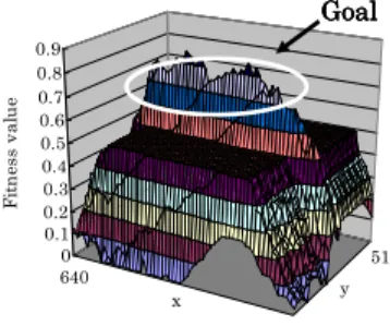
Since the 3-dimensional shape of the goal changes with the view point, it is difficult to specify the spape model. Fur-thermore, it is desirable to recognize the free space without a goal keeper. Then, the goal is recognized by paying atten-tion to the edge of the blue of the goal and the green of the field. The searching model used here is shown in Fig.7. The blue domain contained in a model is evaluated by the upper half of this search model, and the green domain is evaluated by the lower half. In order to extract blue, we regard the value of H in the range of 200-220 as blue and 125-160 as green respectively. Therefore, a set of blue points Ωblue, and
0 0.1 0.2 0.3 0.4 0.5 0.6 0.7 0.8 0.9 F it n e s s v a lu e 640 512 0 x y Goal Goal Goal Goal
Fig. 9. Searching result by model of Fig.7
P m P c ûe= (x; y) S1 S2
Fig. 10. Enemy search model
a set of green points Ωgreen are expressed as the following
equation:
Ωblue='x, y¯¯200< H(x, y) < 220ª, (5)
Ωgreen='x, y¯¯125< H(x, y) < 160ª. (6)
The evaluation function of blue is defined as
hblue(r) = ‰ 1(r∈ Ωblue) 0(r6∈ Ωblue) ¾ , (7)
and the evaluation function of green is defined as
hgreen(r) = ‰ 1(r∈ Ωgreen) 0(r6∈ Ωgreen) ¾ . (8)
The blue domain in the upper half of the model is set toS1, and the green domain of a lower half is set to S2. Fitness function caluculated inS1 andS2 is shown in the following equation: FGoal(φ) = X r∈S1 hblue(r) + X r∈S2 hgreen(r). (9)
The filtering image of Fig.8 by Eq.9 is shown in Fig.9. It is confirmed that the maximum peak in the filtered image Fig.9 shows the position of the goal.
2.1.3 Recognition of Enemy
If the size of the enemy is given, enemy’s position is known from detecting corner “A” and “B”. The corner of the bot-tom of the enemy touches the field in two points like Fig.11. The model of the enemy which detects the corner in two points is shown in Fig.11. Black is recognized by bright-ness value information, because it can not be expressed by
x
y
A
A
A
A
B
B
B
B
Fig. 11. Input image of enemy search
0 0.1 0.2 0.3 0.4 0.5 0.6 0.7 0.8 0.9 F it n e s s v a lu e 640 512 0 x y Enemy Enemy Enemy Enemy
Fig. 12. Searching result by model of Fig.10
H. Fitness function expressed by S1 andS2is shown in the following equation: FRobot(φ) = X r∈S1 pr(r)− X r∈S2 pr(r). (10) The filtering image of Fig.11 by the Eq.10 is shown in Fig.12. It is confirmed that the maximum peak in the filtered image Fig.12 show the position of the robot.
2.2. Real-time Recognition by Gazing Step GA
GA is well known as a parallel search and parameter opti-mization algorithm. The term “parallel”, in “parallel search” above is related to the implicit parallelism of GA. Implicit parallelism is explained in Goldberg (1989, pp.40-41) [4]. The GA is viewed as an optimization method since the it-erative evolution process of the potential solutions toward better solutions is equivalent to the process of optimizing the objective function used as a fitness function in GA search. The GA operates with a population of individuals, which are represented by gene code in this research and are considered to be the potential solutions to a given problem.
To recognize a target in a dynamic image, the recognition system must have real-time nature, that is, the searching model must converge to targets in the successively input images. We have proposed a new idea of an evolutionary recognition process for dynamic image, in which the evolu-tion of GA is applied only one time to the newly input image. Therefore every input image is evaluated only one time, we named it as “Step-GA”[5]. If the pre speed of step-GA is faster than the moving speed of targets, real-time recogni-tion nature can be realizable.
GA adopted in this research includes two main functions, that is, global and local searching, which are switched de-pending on the matching degree of the targets in the raw-image and the model created from the shape of the targets. During the process of the local searching, gazing operation is
(x
g,y
g,í
g)
(x,y)
(x
e,y
e,í
e)
x
y
Fig. 13. Recognition of plural targets
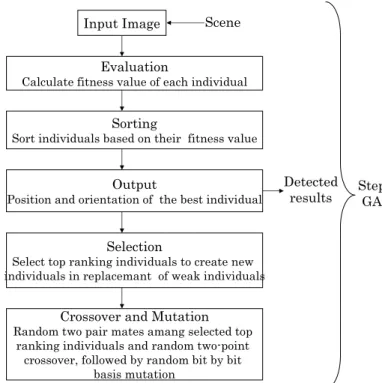
Input Image
Evaluation
Calculate fitness value of each individual
Sorting
Sort individuals based on their fitness value
Output
Position and orientation of the best individual
Selection
Select top ranking individuals to create new individuals in replacemant of weak individuals
Crossover and Mutation
Random two pair mates amang selected top ranking individuals and random two-point
crossover, followed by random bit by bit basis mutation
Scene
Detected results Step GA
Fig. 14. Flow chart of Step-GA
suggested to shorten recognition time and raise the accuracy, which is inspired from gazing action of targets.
3. Real-time Recognition Experiments We have performed the experiments that the ball, the goal and the robot are recognized from dynamic image using the method described above. Three genes are used respectively to search for the ball, the goal, and the enemy robot. QRPT is a recognition process for the position of the ball(x,y), the position of shoot to the goal(xg,yg,θg) and the position of the
robot(xr,yr,θr) as shown in Fig.13 by video rate (less than 30[fps]) simultaneously from dynamic image. Flow chart of Step-GA is shown in Fig.14. Flow chart of plural targets de-tection is shown Fig.15. Table 1 shows the parameter of GA used in this experiment for the ball and Table 2 for the goal and the enemy. Generally, the less the number of individuals is, the less time the evolution of GA applied one time will cost. However, fewer individuals will also cause the problem
initialization
Ball detected
Goal detected
Enemy detected Input image
Fig. 15. Flow chart of plural targets detection
that the fitness function could not be converged completely during the evolution process of GA. In this paper, the num-ber of individuals is given as 50 to ensure the evolution time is less than 33[ms] for one generation and the fitness func-tion is converged thoroughly. Then the object recognifunc-tion is processed in real time. The result of QRPT experiment is shown in Fig.16. A round frame shows the outline of the detected ball, the red line extending from the bottom of the image shows the direction of the goal, and the position of the enemy is expressed by the white L-shape. Moreover, since the direction of red line which points to the goal will change if the keeper moves, this line expresses the direction of the goal which is possible to be shoot.
4. Generation of Adaptive Motion In the recent research, the robot navigation is processed us-ing the position information of the object in the world co-ordinate transformed from the image coco-ordinate. However, using sight information input from directly eyes, human be-ings can realize the position of the object from its size etc. We aim at the establishment of the visual system that similar
Table 1. Parameter of GA(Ball)
Population size 50 individuals Selection rate Two-point crossover 0.5
Mutation rate 0.1 Length per individual 12 bits
Elitist model yes
Table 2. Parameter of GA(Goal,Enemy)
Population size 50 individuals Selection rate Two-point crossover 0.5
Mutation rate 0.1 Length per individual 21 bits
Fig. 16. Experiments of quasi-simultaneous recognition of plural targets
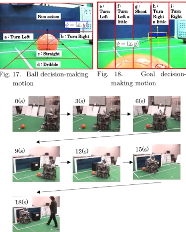
to human beings. Therefore, the robot action is generated by the object position obtained from the image recognition using Model-based Matching method in which the raw image is used directly. In this research, an area chart in which the input image is dividing into several small parts is proposed to determine the robot action. Such a chart is named as an action generation map. For the action to the ball the ac-tion generaac-tion map is utilized in which the input image is divided from a to d, shown in Fig.17.
• If the ball is in the range of a, the robot turns to the left.
• If the ball is in the range of b, the robot turns to the right.
• If the ball is in the range of c, the robot runs straight.
• If the ball is in the range of d. the robot dribbles No action is defined in the upper 1/3 part of the recognition image, shown in Fig.17, since the ball does not exist in this part of area in a present experimental environment. The robot runs straight when the ball is in the position shown in Fig.17. For action generation to get a goal, the input image is divided into five parts longitudinally from e to i. The action generation map of the goal recognition is shown in Fig.18.
• If goal is in the range of e, the robot turns left.
• If goal is in the range of f, the robot turns left a little.
• If goal is in the range of g, the robot starts soot action.
• If goal is in the range of h, the robot turns right a little.
• If goal is in the range of i, the robot turns right. For example, when the goal position is recognized as shown in Fig.18 the robot turns right a little. In addition, the shoot action is performed by the mobile robot which accelerates rapidly to throw the ball away. The robot stops when the speed is over 0.73[m/s], since the safety-area should be left. The condition for a robot to start the shoot action is below.
1. The robot dribbles the ball.
a : Turn Left a : Turn Left a : Turn Left
a : Turn Left b : Turn Right b : Turn Right b : Turn Right b : Turn Right
d : Dribble d : Dribble d : Dribble d : Dribble û= (x; y) c : Straight c : Straight c : Straight c : Straight Non action Non actionNon action Non action
Fig. 17. Ball decision-making motion e : e : e : e : Turn Turn Turn Turn Left Left Left Left f : f : f : f : Turn Turn Turn Turn Left a Left a Left a Left a little little little little g : g : g : g : Shoot Shoot Shoot Shoot h : h : h : h : Turn Turn Turn Turn Right Right Right Right a little a little a little a little i : i : i : i : Turn Turn Turn Turn Right Right Right Right û= (x; y)
Fig. 18. Goal decision-making motion
0(s) 3(s) 6(s)
9(s) 12(s) 15(s)
18(s)
Fig. 20. Experiment appearance
2. The goal exists in the traveling direction.
3. The distance between the robot and the goal is within 1.5m.
The condition of 1 and 2 means that the ball is in the range of d in Fig.17 and the goal is recognized within the range of g in Fig.18. In the condition 3 the distance to the goal from the robot by dead reckoning. We assume is obtained the initial position of the robot is known.
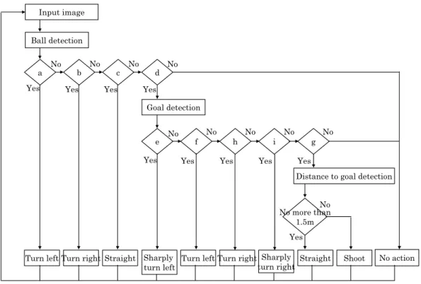
5. Experiments of Action Generation To show the effectiveness of the proposed method experi-ment has been conducted for the robot to find and run after the ball, dribble it and shoot it to the goal. The size of the field and the goal were formed based on RoboCup medium size league in 2002. One side of the field is used for our ex-periment. The flow chart of the action generation is shown in Fig.19. Initially, the ball was put on the center of the field and the robot was put on the right. Moreover, a black ob-stacle was put in front of the goal instead of goalkeeper.The part of the goal is covered by the goalkeeper. Thus the robot has to choose the shoot direction based on target recognition. Shoot action in experiment is shown Fig.20. The upper left of the figure shows times.
In such initial condition the trajectory of the soccer robot obtained by dead reckoning is shown in Fig.21. It shows the robot moved to the ball, dribbled it, and shot it to the goal. It shows the action of the soccer robot is realized by the proposed method.
a No more than 1.5m g i h f e d c b Goal detection
Distance to goal detection
Shoot Straight Sharply turn right Turn right Turn left Sharply turn left Straight Turn right Turn left Yes No No No No No No No No No Yes
Yes Yes Yes Yes
Yes Yes Yes Yes No action No Ball detection Input image
Fig. 19. Flow chart of adaptive motion
0
1
2
3
0
1
2
3
Goal Initial Ball PositionGoal Keeper Initial Position
End Position
Fig. 21. Vehicular swept path
6. Conclusion
We proposed the motion control method of robot by QRPT. Model-based matching method is used to recognize the tar-gets, and recognition processing time was shortened by GA. The motion control of soccer robot was realized using the image position of the target obtained by the proposed recog-nition method. Finally, the experiment about QRPT and motion control of soccer robot shows the effectiveness of the proposed method.
References
[1] R.A.Brooks, Model-Based Three-Dimensional
Interpre-tations of Two-Dimensional Images, IEEE Transaction on Pattern Analysis and Machine Intelligence, PAMI-5, 2, pp.140-150, 1983.
[2] M.Minami, J.Agbanhan and T.Asakura, A Method of
Model-Based Object Recognition, Japan/USA
Sympo-sium on Flexible Automation (ASME), Vol.2, pp.905-912, 1996.
[3] M.Minami, H.Suzuki, M.Miura, Real-Time Robust Recognition of Human using Illuminance-depending Gazing GA, Knowledge-Based Intelligent Information Engineering Systems and Allied Technologies, KES 2002, pp.1377-1382.
[4] D.E.Goldberg, Genetic algorithm in Search,
Optimiza-tion and Machine Learning. Reading, Addison-Wesley, 1989.
[5] M.Minami, J.Agbanhan and T.Asakura, Manipulator
Visual Servoing and Tracking of Fish Using Genetic Al-gorithm, Int. J. of Industrial Robot, 29-4, pp.278-289, 1999.
[6] M.Minami, H.Suzuki, J.Agbanhan, T.Asakura, Visual
Servoing to Fish and Catching Using Global/Local GA Search, Int. Conf. on Advanced Intelligent Mechatron-ics, Proc., 2001, pp.183-188.
[7] Ernst Dieter Dickmanns,Volker Graefe, Dynamic Monocular Machine Vision, Machiine Vision and Application(1988)pp.223-240,(1988).
[8] M,Minami.H,Suzuki,Y,Sakamoto, Quasi-simultaneous
Recognition of Plural Targets for Soccer Robot and Mo-tion Control, SICE2004.CD-ROM.