저작자표시-비영리-변경금지 2.0 대한민국 이용자는 아래의 조건을 따르는 경우에 한하여 자유롭게 l 이 저작물을 복제, 배포, 전송, 전시, 공연 및 방송할 수 있습니다. 다음과 같은 조건을 따라야 합니다: l 귀하는, 이 저작물의 재이용이나 배포의 경우, 이 저작물에 적용된 이용허락조건 을 명확하게 나타내어야 합니다. l 저작권자로부터 별도의 허가를 받으면 이러한 조건들은 적용되지 않습니다. 저작권법에 따른 이용자의 권리는 위의 내용에 의하여 영향을 받지 않습니다. 이것은 이용허락규약(Legal Code)을 이해하기 쉽게 요약한 것입니다. Disclaimer 저작자표시. 귀하는 원저작자를 표시하여야 합니다. 비영리. 귀하는 이 저작물을 영리 목적으로 이용할 수 없습니다. 변경금지. 귀하는 이 저작물을 개작, 변형 또는 가공할 수 없습니다.
THESIS
FOR THE DEGREE OF MASTER OF PHILOSOPHY
Modeling and Analysis of DFIG Operation
under Unbalanced Grid Voltage and
Non-linear Load Conditions
Quach Ngoc Thinh
Faculty of Applied Energy System
Major of Electrical Engineering
GRADUATE SCHOOL
JEJU NATIONAL UNIVERSITY
Modeling and Analysis of DFIG Operation
under Unbalanced Grid Voltage and
Non-linear Load Conditions
Quach Ngoc Thinh
(Supervised by Professor Eel-Hwan Kim)
A thesis submitted in partial fulfillment of the requirements
for the degree of Master of Philosophy
2011. 12
This thesis has been examined and approved
Thesis director, Chong Keun Jwa, Prof. of Electrical Engineering
………
Se-Ho Kim, Prof. of Electrical Engineering
………
Eel-Hwan Kim, Prof. of Electrical Engineering
………
FACULTY OF APPLIED ENERGY SYSTEM
GRADUATE SCHOOL
Acknowledgement
First of all I would like to show my deepest gratitude to my supervisor, Prof. Eel-Hwan Kim for all of his helps about financial support, encouragement, invaluable and endless guidance from the beginning to the end of my course. The days of mine at Jeju National University would not have passed quickly if I had not received his helps.
Also I would like to thank other Professors at Department of Electrical Engineering, Prof. Seong Bo Oh, Prof. Chong Keun Jwa, Prof. Kea Myoung Lee, Prof. Se Ho Kim, and Prof. Ho Chan Kim for teaching me during the Master’s course. Their direction helped me to broaden my view and knowledge.
I am grateful to all the staff at the Department of Electrical Engineering for sharing information.
My heartiest thank to our group, Jea Hong Kim, Jin Hong Ahn, Dea Huyn Kim, Myung Suk Kang, Kyung Min Jin, Dong Wan Kim for making me feel welcome and for a pleasant working atmosphere during my course.
The support and encouragement from my parent and friends in Vietnam have been crucial for me – thanks for having said what you said and having done what you did.
Abbreviations
PWM Pulse-Width Modulation
DFIG Doubly Fed Induction Generator GSC Grid Side Converter
RSC Rotor Side Converter PI Proportional-Integral PR Proportional-Resonant AC Alternating Current DC Direct Current
MPPT Maximum Power Point Tracking PCC Point of Common Coupling
List of symbols
αβ Stationary reference frame
(dq) or (dq)+ Synchronous rotating reference frame
(dq)- Negative synchronous rotating reference frame Vw Wind speed
Tm Mechanical torque
Te Electromagnetic torque
TL Load torque
ωr Rotor electrical speed
ωe Synchronous rotating speed
ωs Stator angular frequency
Pm Mechanical output power
Pe Electromagnetic power
Ps Stator active power
Pr Rotor active power
Pg Grid active power
Qs Stator reactive power
ρ Air density R Blade radius
Cp Maximum power conversion coefficient
λ Tip-speed ratio ωrot Blade rotational speed
θ Pitch angle Vs (Vas, Vbs, Vcs) Stator voltage
Vds d – axis stator voltage
Vqs q – axis stator voltage
Is (Ias, Ibs, Ics) Stator current
Ids d – axis stator current
Iqs q – axis stator current
ψs Stator flux
ψds d – axis stator flux
ψqs q – axis stator flux
Vαs α – axis stator voltage
Iαs α – axis stator current
Iβs β – axis stator current
ψαs α – axis stator flux
ψβs β – axis stator flux
Vr Rotor voltage
Vdr d – axis rotor voltage
Vqr q – axis rotor voltage
Ir Rotor current
Idr d – axis rotor current
Iqr q – axis rotor current
ψr Rotor flux
ψdr d – axis rotor flux
ψqr q – axis rotor flux
Iαr α – axis rotor current
Iβr β – axis rotor current
Vg (Vag, Vbg, Vcg) Grid voltage
Ig (Iag, Ibg, Icg) Grid current
Vdg d – axis grid voltage
Vqg q – axis grid voltage
Idg d – axis grid current
Iqg q – axis grid current
Iαg α – axis grid current
Iβg β – axis grid current
Iαh α – axis harmonic current
Iβh β – axis harmonic current
Rf Resistance of grid side converter
Lf Inductance of grid side converter
Rs Stator resistance
Rr Rotor resistance
Lm Magnetizing inductance
Lσs Stator linkage inductance
Lσr Rotor linkage inductance Ls Stator inductance
Lr Rotor inductance
σ Leakage factor θs Stator flux angle
θg Grid voltage angle
θr Rotor angle
θsl Slip angle
Gαβ(s) Transfer function of resonant controller
GPR(s) Transfer function of proportional-resonant controller
ωc Bandwidth of resonant filter
Vdc dc-link voltage
P Number of poles C Capacitor
Abstract
This thesis presents the modeling and analysis of doubly fed induction generator (DFIG) operations under unbalanced grid voltage in the normal and non-linear load conditions. For the simulations, a novel control strategy for wind power generation system is also applied. The oscillations of the DFIG electromagnetic torque and power in the stator side are fully described in the unbalanced grid voltage. Besides, the harmonic current components in the network which come from non-linear loads are also analyzed. A current controller, proportional-resonant (PR) controller, implemented in the stationary reference frame is proposed to mitigate the negative sequence current components in both grid side converter (GSC) and rotor side converter (RSC). To provide enhanced operation, the RSC is controlled to mitigate the stator active power and the rotor current oscillations at double supply frequency under unbalanced grid voltage while the GSC is controlled to mitigate ripples in the dc-link voltage and compensate harmonic components of the network currents. Simulation results using Psim simulation program are presented for a 2 MW DFIG wind generation system to explain the operations of DFIG under normal conditions and confirm the effectiveness of the proposed control strategy during unbalanced gird voltage and non-linear load conditions.
Key words: Wind turbine, DFIG, Unbalanced grid voltage, Non-linear load, GSC, RSC, Stator active power oscillation, dc-link voltage.
Contents
List of figures ... viii
I. Introduction ... 1
1.1 Theoretical and historical background ... 1
1.2 Purpose of the thesis ... 2
1.3 Thesis layout ... 3
II. The modeling of DFIG ... 4
2.1 Wind turbine operation ... 4
2.2 Doubly fed induction generator control ... 7
2.2.1 DFIG equivalent circuit and equations... 8
2.2.2 Rotor side converter control ... 10
2.2.3 Grid side converter control ... 13
III. The design of proposed control strategies ... 15
3.1 Proportional-resonant (PR) control ... 16
3.2 Rotor side converter ... 18
3.2.1 The operation of RSC under unbalanced grid voltage ... 18
3.2.2 Proposed control strategy for RSC ... 21
3.3 Grid side converter ... 22
3.3.1 The operation of RSC under unbalanced gird voltage ... 22
3.3.2 Non-linear load... 23
3.3.3 Proposed control strategy for GSC ... 24
IV. Simulation results ... 26
4.1 DFIG normal operation ... 26
4.2 DFIG operation with non-linear load ... 33
4.3 DFIG operation under unbalanced grid voltage condition ... 35
V. Conclusion ... 37
Appendix ... 38
List of figures
Fig. 1 Power extraction for a wind turbine ... 4
Fig. 2 Wind turbine power curve ... 4
Fig. 3 Variable of power conversion coefficient with pitch angle θ ... 5
Fig. 4 Pitch angle θ (theta) required for constant 2 MW power output in the power limitation wind speed range ... 6
Fig. 5 Diagram of pitch angle control ... 7
Fig. 6 Configuration of overall control system ... 8
Fig. 7 Dynamic d-q equivalent circuits of a DFIG in the synchronous rotating frame ... 9
Fig. 8 Vector diagram with stator flux oriented vector control ... 11
Fig. 9 Rotor side converter control block diagram... 13
Fig. 10 Grid side converter control block diagram ... 14
Fig. 11 Configuration of overall proposed control system ... 15
Fig. 12 Bode diagram of ideal and non-ideal PR controllers ... 17
Fig. 13 Resonant filter of the 3rd, 5th, 7th harmonics ... 18
Fig. 14 Relationships between the (αβ)s, (αβ)r, and the (dq) + and (dq)- reference ... 19
Fig. 15 The two reference frames: synchronous and negative synchronous ... 21
Fig. 16 Proposed control strategy for RSC ... 22
Fig. 17 Non-linear load with the three-phase diode rectifier ... 24
Fig. 18 Proposed control strategy for GSC ... 25
Fig. 19 Decoupled control of stator active and reactive power ... 27
Fig. 20 The operation of DFIG in case of low wind speed ... 28
Fig. 21 The operation of DFIG in case of high wind speed ... 29
Fig. 22 DC-link voltage control ... 30
Fig. 23 The overall normal operation of 2MW DIFG at steady state ... 31
Fig. 24 Dynamic responses of system under non-linear load ... 33
Fig. 25 Simulation results under transient unbalanced grid voltage of 3.5% during 6.5-7s ... 35
I. Introduction
1.1 Theoretical and historical background
Depletion of fossil fuels and the concomitant climate change have compelled nations to seek new, nonpolluting ways to produce energy. Consequently, renewable energies like wind, solar, biomass, and geothermal energies have been viewed as attractive solutions. The use of wind power has been increasing in several years. To convert wind energy into electric energy, three types of wind generator systems have used: (1) constant-speed wind turbine system with a standard squirrel-cage induction generator, (2) variable speed wind turbine system with a doubly fed induction generator, (3) variable speed wind turbine system with full-rated power electronic conversion system and a synchronous generator.
Nowadays, variable-speed wind turbines based on doubly-fed induction generator (DFIG) are widely used in wind generation with many advantages over the fixed-speed generators, including variable-speed constant frequency operation, reduced flicker and independent control capabilities for active and reactive powers [1]. The superior characteristics are basically achieved by using back-to-back PWM voltage source converter, which is typically rated at around 30% of the generator rating for a given rotor speed variable range of ±25% under normal operation conditions. The stator of DFIG is connected directly to the network while the rotor of DFIG is connected through a rotor side converter (RSC), the dc-link and a grid side converter (GSC) to the grid. The basic operations of DFIG are to maximize the wind power capture at different wind speeds and ensure the quality of power output.
Under symmetrical stator voltage supply, the response and performance of wind turbines based DFIG during steady state and transient conditions are now well understood [1]-[6]. However, both transmission and distribution networks can undergo voltage unbalance in the practical system. Under unbalanced stator voltage conditions, it supplies a negative sequence component to the stator and rotor voltage. Consequently, it will be able to give rise to high frequency components in the rotor currents, torque, dc-link voltage oscillations in the power converter, and output power oscillations which can cause excessive shaft stress and winding losses.
If the voltage unbalance is over 2%, it will cause a large number of disconnections from the network. The control and operation of DFIG under unbalanced stator voltage condition have researched in the literature [7]-[14]. In [7], the author focuses for analysis of harmonic in a DFIG caused by non-sinusoidal conditions in rotor and unbalance in stator. During unbalanced stator conditions, symmetric component theory is applied to the stator voltage to
get positive-, negative-, and zero-sequence components of stator and rotor currents. The torque oscillation can be eliminated by using the negative sequence compensation techniques via the RSC or the GSC. The RSC compensation supplies the negative sequence voltages to the rotor circuit [9]-[11] to eliminate the negative sequence components in the rotor currents while the GSC compensation supplies the negative sequence current to the grid [14] to keep the stator currents free of the negative sequence components. To eliminate the dc-link voltage oscillations and at the same time to eliminate the oscillation in the rotor currents and the torque, the control strategies are also adopted in [11], [13]-[15]. The proposed methods in [9]-[12] via proportional-integral (PI) controller require the analysis of synchronous (dq)+ and negative synchronous reference frame (dq)- that are fairy complex because the complicated computation of the reference current values and the usage of low pass filters for sequence component separation. In [12], a proportional-integral controller and a harmonic resonant (R) compensator tuned at twice the grid frequency are consisted. Recently, the stationary reference frame (αβ) is used and proportional-resonant (PR) controller is adopted [8], [13], while the ability for harmonic mitigation in DFIGs of PR controllers are presented in [17].
1.2 Purpose of the thesis
This thesis presents a modeling of a DFIG based on wind energy conversion system. The main objective of DFIG control under normal operations is to achieve maximum power output from different wind speeds by applying maximum power point tracking (MTTP) control into wind turbine control.
Simultaneously, this thesis also proposes an easy control strategy to mitigate the oscillation in the torque, the stator active power, and the dc-link voltage during unbalanced stator voltage conditions by using PR controllers. In this case, PR current controllers will be applied to both RSC and GSC. The advantages of the PR controller are: (i) only one transformation (abc/αβ) is required and (ii) harmonic filters are not required.
Besides, the ability of using the GSC as STATCOM to compensate harmonic currents to the network under non-linear load conditions is also investigated. A resonant filter is used to isolate harmonic currents and its control loops are applied to the GSC control algorithm, so that harmonic current components can be injected into the network at the point of common coupling (PCC). Thus, the network currents will be quasi-sinusoidal.
1.3 Thesis layout
Chapter 2 presents the analysis of the behavior and operation of the wind turbine and DFIG system.
Chapter 3 describes the proposed control strategies for RSC and GSC based on PR current controllers.
Chapter 4 gives simulation results on a 2 MW DFIG system. Chapter 5 draws the conclusions.
II. The modeling of DFIG
2.1 Wind turbine operation
A wind turbine obtains its power input by converting some of the kinetic energy in the wind into torque acting on the rotor blades. The amount of captured energy in a wind turbine depends on the wind speed, the blade swept area, pitch angle and the air density. Although there are many different configurations of wind turbines but they all work in a similar way. A simple explanation for conversion of wind energy into electric energy is presented as Fig. 1.
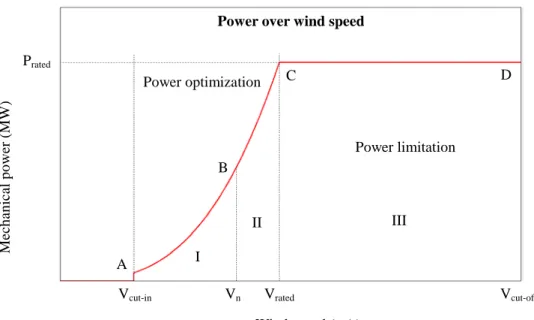
The turbine starts to produce energy when the wind speed is above Vcut-in and stops when
the wind speed is over Vcut-off as Fig. 2.
There are two controls strategies (two control modes) and three different control sections for the control of the variable speed wind turbine:
- Power optimization strategy (below rated wind speed Vrated) where the energy capture
Fig. 1 Power extraction for a wind turbine
Wind Energy Actuator Disc Drive- train Generator Vw Tm ωr ωe Te Pt
Fig. 2.2 Wind turbine power curve
Wind speed (m/s)
Fig. 2 Wind turbine power curve
Prated
Power optimization
Power limitation
Power over wind speed
Vrated M ech an ical p o w er ( MW ) Vcut-in Vcut-off A B C D I II III Vn
is optimized. It is depicted by the range A-B-C in Fig. 2.
In this control mode, the pitch θ-values are looked up in a table. The θ-value corresponding to optimal Cp-values have to be found in the Cp table, which describes the
aerodynamic properties of the blades.
In order to achieve maximum power yield for each wind speed the maximal Cp and the
corresponding θ has to be found, because the aerodynamic power is calculated according to:
( )
θλ ρπ = R V C , 2 1 Pm 2 w3 p (1)where the tip-speed ratio λ is defined as
w rot V R ω = λ (2)
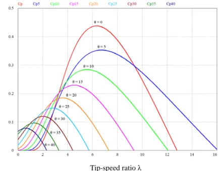
The relation between the power coefficient Cp, the tip-speed ratio λ, and the pitch angle θ
is pointed out as Fig. 3.
From (1) and Fig. 3, it is apparent that the power production from the wind turbine can be maximized if the system is operated at maximum Cp.
- Power limitation (above rated wind speed Vrated) where the aim of the controller is to
track the nominal (rated) power reference of the wind turbine. It is depicted by the range C-D in Fig. 2.
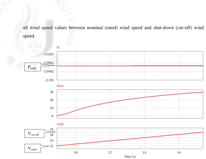
To get the power limitation, the blades have to be pitched in positive direction when electrical power exceeds nominal power.
Fig. 4 illustrates how the pitch angle has to be adjusted in order to get nominal power for
P o we r co ef fi ci en t C p Tip-speed ratio λ
all wind speed values between nominal (rated) wind speed and shut-down (cut-off) wind speed.
Section I [Vcut-in…Vn]: This case corresponds to the situation when the rotational speed is
higher than the lower limit and less than the nominal rotational speed ωrotmin < ωrot ≤ ωrotnom. The aim is to maximize the energy capture by tracking the maximum power coefficient Cpmax curve. The maximum power coefficient value Cpmax corresponds to one pitch angle θopt and
one tip speed ratio λopt. Therefore, the pitch angle is kept constant to the optimal value θopt,
while the tip speed ratio is tuned to the optimal value λopt over different wind speeds.
Section II [Vn…Vrated]: This case corresponds to the situation when the turbine speed is
restricted to the nominal value ωrotref = ωrotnom and when the generated power is less than the rated value Pm < Pmrated . The highest efficiency is obtained by operating the turbine at nominal speed ωrotnom. In this case, the tip speed ratio, the maximum power coefficient value, the optimal pitch angle and the optimal power are determined based on ωrotnom.
Section III [Vrated…Vcut-off]: This case corresponds to the situation of wind speeds higher
than the rated wind. The reference output power is the rated mechanical power Pmref = Pmrated while the reference rotor speed is the nominal rotor speed ωrotref = ωrotnom. Thus, for each wind speed, the power coefficient is adjusted to limit the output power to the rated power.
Vrated
Vcut-off
Prated
Fig. 4 Pitch angle θ (theta) required for constant 2 MW power output in the power limitation wind speed range
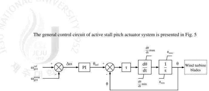
The general control circuit of active stall pitch actuator system is presented in Fig. 5
2.2 Doubly fed induction generator control
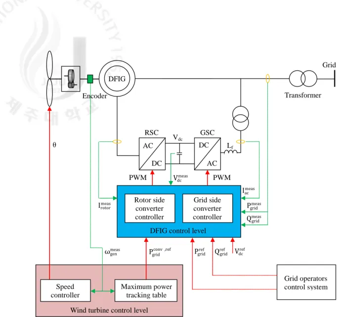
The DFIG system used in this thesis is shown in Fig. 6. In the following, the function is explained. The stator side of DFIG is connected to the three phase supply. To match the stator voltages with the three phase supply, a three phase transformer could be used. The shaft of the generator receives mechanical power from the wind powered blades of the turbine.
In the rotor side, a back to back converter system is implemented and applied the vector control method. Measurement blocks are needed to acquire elements needs for the control. An encoder is needed to obtain the rotor position and speed. Operation of the machine is set by controlling of the two converters from sub to super synchronous speed.
- Rotor side converter controls independently the active and reactive power on the grid. - Grid side converter controls the dc-link voltage Vdc and ensures unity power factor in
the rotor branch. The transmission of the reactive power from DFIG to the grid is thus only through the stator.
The wind turbine control provides reference signals both to the pitch control system and to the generator speed control. It contains two controllers like below:
- Speed controller has as mission to control the generator speed at high wind speed, example to change the pitch angle to prevent the generator speed becoming too high. At low wind speeds, the pitch angle is kept constant to an optimal value.
- Maximum power point tracking controller generates the active power reference signal for the active power control loop, performed by the rotor side converter. This reference signal is determined from the predefined characteristic P-ω look-up table.
PI τ dθ dt 1 s dθ dt max θref
ωgenref Wind turbine blades
dθ dt min θmax θmin ωgenmeas Δω + θ + - -θ
2.2.1 DFIG equivalent circuit and equations
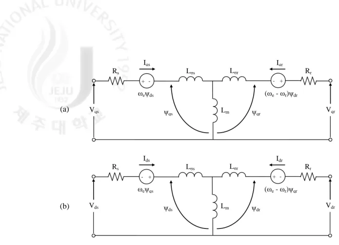
The dynamic d-q equivalent circuits of a DFIG in the synchronous rotating frame are shown in Fig. 7.
Equations of the machine are presented in synchronous rotating frame. These equations can be rewritten in the desired reference frame by replacing ωe with the reference frame speed.
The stator voltage equations are presented below:
ds e qs qs s qs dt d I R V = + ψ +ω ψ (3) qs e ds ds s ds dt d I R V = + ψ −ωψ (4)
The stator voltages may be expressed as a sum of the d and q voltage components:
qs ds s V jV V = + (5) DFIG RSC GSC Grid DC Transformer AC AC DC Vdc PWM Pgridref Grid operators control system PWM Vdcmeas Iacmeas Pgridmeas Qgridmeas Vdcref Qrefgrid Irotormeas
ωgenmeas Pgridconv ,ref
θ Rotor side converter controller Grid side converter controller DFIG control level
Wind turbine control level Maximum power
tracking table Speed
controller
Fig. 6 Configuration of overall control system
Encoder
Fig. 7 Dynamic d-q equivalent circuits of a DFIG in the synchronous rotating frame (a) q – axis circuit, (b) d – axis circuit
The stator and rotor current are also expressed in d and q components:
qs ds s I jI I = + (6) qr dr r I jI I = + (7)
The stator and rotor flux:
qs ds s=ψ +jψ ψ (8) qr dr r =ψ +jψ ψ (9)
The rotor voltage equations:
(
e r)
dr qr qr r qr dt d I R V = + ψ + ω −ω ψ (10)(
e r)
qr dr dr s dr dt d I R V = + ψ − ω −ω ψ (11) Similar to the stator voltage, the rotor voltage may be also expressed as a sum of the d and q voltage components:qr dr r V jV
V = + (12)
The power equations:
(
ds ds qs qs)
s V I V I 2 3 P = + (13) + -+ Rs Iqs Lσs Lσr Iqr Rr Vqr (ωe - ωr)ψdr Lm ωeψds Vqs ψqs ψqr -+ + -Rs Ids Lσs Lσr Idr Rr Vdr (ωe - ωr)ψqr Lm ωeψqs Vds ψds ψdr (a) (b)(
qs ds ds qs)
s V I V I
2 3
Q = − (14)
The mechanical equation comprising the rotor inertia J, load torque TL, and
electromagnetic torque Te and rotor speed ωr is written as following:
L e r T T dt d J ω = − (15)
The electromagnetic torque is a function of the machine pole number (P) and stator (or rotor) currents and fluxes:
(
ds qs qs ds)
e I I 2 P 2 3 T =− ψ −ψ (16) or(
dr qr qr dr)
e I I 2 P 2 3 T =− ψ −ψ (17)The stator flux linkage equations:
qr m qs s qs=LI +L I ψ (18) dr m ds s ds=LI +L I ψ (19) where Ls = Lm + Lσs (20)
The rotor flux linkage equations:
qs m qr r qr =L I +L I ψ (21) ds m dr r dr =L I +L I ψ (22) where Lr = Lm + Lσr (23)
2.2.2 Rotor side converter control
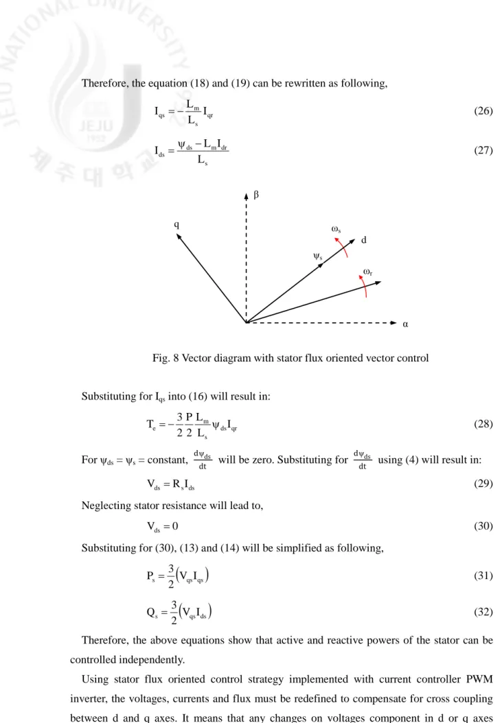
The generator controller is in charge of accurately controlling the active power of the system. The generator controller adopts the stator flux oriented vector control strategy. This strategy converts the generator’s current and voltage into a reference frame which rotates at the synchronous speed. The d axis of this reference frame aligns with the stator flux vector. Fig. 8 displays the vector diagram of the stator flux oriented vector control strategy.
With stator flux oriented vector control, as shown in the vector diagram of Fig. 8,
ψqs = 0 (24)
Therefore, the equation (18) and (19) can be rewritten as following, qr s m qs I L L I =− (26) s dr m ds ds L I L I =ψ − (27)
Substituting for Iqs into (16) will result in:
qr ds s m e I L L 2 P 2 3 T =− ψ (28) For ψds = ψs = constant, dψds
dt will be zero. Substituting for dψds
dt using (4) will result in:
ds s
ds R I
V = (29)
Neglecting stator resistance will lead to, 0
Vds= (30)
Substituting for (30), (13) and (14) will be simplified as following,
(
qs qs)
s V I 2 3 P = (31)(
qs ds)
s V I 2 3 Q = (32)Therefore, the above equations show that active and reactive powers of the stator can be controlled independently.
Using stator flux oriented control strategy implemented with current controller PWM inverter, the voltages, currents and flux must be redefined to compensate for cross coupling between d and q axes. It means that any changes on voltages component in d or q axes results in changes in both current components. The following parameter called leakage factor
Fig. 8 Vector diagram with stator flux oriented vector control
α d β q ω s ωr ψs
of induction generator is defined in literature: r s 2 m L L L 1− = σ (33)
Substituting (26) and (27) into (21) and (22), respectively, we get:
qr r qr=σLI ψ (34) ds s m dr r dr L L I L + ψ σ = ψ (35)
Substituting these equations into (10) and (11), the voltage equations of the rotor can be rewritten as following: comp qr ' qr qr V V V = + (36) comp dr ' dr dr V V V = + (37) dt dI L I R Vqr' = r qr+σ r qr (38) dt dI L I R V dr r dr r ' dr = +σ (39)
(
)
ds(
e r)
r dr s m r e comp qr LI L L V = ω −ω ψ + ω −ω σ (40)(
e r)
r qr ds s m comp dr LI dt d L L V = ψ − ω −ω σ (41)The compensation voltage terms, comp dr
V and comp qr
V , make it possible to achieve decoupled control of the stator flux oriented control of the rotor side converter. So each axis reference frame voltage of the rotor can be controlled by using each axis reference frame current.
The stator flux is calculated as
(
Vs RsI s)
dt s∫
β β β = − ψ (42)(
Vs RsI s)
dt s∫
α α α = − ψ (43)and the flux position by using above equations as
s s 1 s tan α β − ψ ψ = θ (44)
The stator flux oriented control strategy of the rotor side converter based on the normal current controllers, proportional-integral (PI) current controllers, is presented in Fig. 9.
2.2.3 Grid side converter control
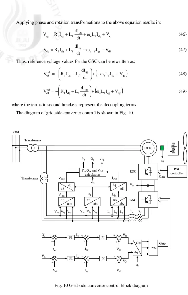
The aim of the control of the GSC is to maintain the dc-link capacitor voltage in a set value regardless of the magnitude and the direction of the rotor power and to ensure a converter operation with unity power factor (zero reactive power). This means that the GSC exchanges only active power with the grid, and therefore the transmission of reactive power from DFIG to the grid is done only through the stator.
Based on Fig. 6, the voltage equations across the inductor can be written as following:
+ + = 1 c 1 b 1 a cg bg ag f cg bg ag f cg bg ag V V V I I I dt d L I I I R V V V (45) Fig. 9 Rotor side converter control block diagram
Idr∗ Qs∗ Qs Idr Vd PI PI -+ -+ + + Iqr∗ Ps∗ Ps Iqr Vq PI PI -+ -+ + + Vdr∗ Vqr∗ abc Vas Vαβs Rotor position Stator flux angle calculation θsl PWM Vbs Vcs Ias Ibs Ics αβ abc αβ abc αβ Iαβs αβ αβ dq dq αβ dq Stator flux calculation Ps and Qs calculation Rotor flux angle calculation Feed-forward voltage calculation angle slip calculation Vdqs Idqs Idqr Ps Qs θs θr θr θs ωr ωr ωe ψdqr ψdqs Iαβr Icr Ibr Iar Vdq DFIG Transformer Grid dq abc θsl Gate Vdc RSC
Fig. 10 Grid side converter control block diagram
Applying phase and rotation transformations to the above equation results in:
1 q dg f e qg f qg f qg L I V dt dI L I R V = + +ω + (46) 1 d qg f e dg f dg f dg L I V dt dI L I R V = + −ω + (47)
Thus, reference voltage values for the GSC can be rewritten as:
(
e f dg qg)
qg f qg f ref 1 q L I V dt dI L I R V + −ω + + − = (48)(
e f qg dg)
dg f dg f ref 1 d L I V dt dI L I R V + ω + + − = (49)where the terms in second brackets represent the decoupling terms. The diagram of grid side converter control is shown in Fig. 10.
Idg∗ Qg∗ Qg Idg Vd1 PI PI -+ -+ + + Iqg∗ Vdc∗ Vdc Iqg Vq1 PI PI -+ -+ + + Vd1∗ Vq 1∗ Vag Vbg Vcg Vag Vbg Vcg Iag Ibg Icg abc αβ αβ dq abc αβ abc αβ αβ dq Vαβg Iαβg Vdqg Idqg ωe Pg Qg Vdq1 θg RSC controller Pg, Qg, and Vdq1 calculation ωr Vdc Lf Rf dq abc θg PWM Gate RSC GSC Gate Transformer Transformer Grid DFIG
III. The design of proposed control strategies
Grid codes for wind turbines, which are specified by transmission system operators, demand that newly installed wind turbines must not be disconnected in case of unbalanced grid voltage, as this would mean a disconnection of significant amount of electrical power due to the increasing penetration of wind power. Thus, modern wind turbines are required to work as a conventional power plant does.
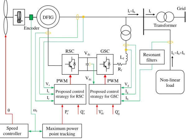
The purpose of this chapter is to analyze and design control strategy for a specific DFIG, which enables the DFIG to contribute to power system stability support, when the DFIG operates under unbalanced grid voltage conditions by using proportional-resonant current controllers. Besides, the ability of GSC control as a STATCOMis also presented in case of non-linear load. A resonant filter is proposed to extract harmonic components, which come from the currents of non-linear load, and compensate to the network currents.
The overall proposed control system for DFIG is depicted in Fig. 11.
Fig. 11 Configuration of overall proposed control system
Resonant filters Lf Encoder DFIG RSC GSC Grid Transformer Vdc Ig Ps∗ θ Proposed control strategy for RSC Proposed control strategy for GSC Maximum power point tracking Speed controller Vg Ih Is Vs Ir Vdc PWM PWM Q∗s Vdc∗ Qg∗ Rf ωr IL=Ib+Ih It+Ih It Non-linear load
3.1 Proportional-resonant (PR) control
For three-phase system, elimination of the steady-state tracking error is usually performed by the first transforming the feedback variable to the synchronous d-q reference frame before applying PI control. Using this method, double computational effort must be devoted under unbalanced conditions, during which transformations to both the positive- and negative sequence reference frames are required. An alternative simpler method of implementation is therefore desired and can be derived by inverse transformation of the synchronous controller back to the stationary α-β frame. The inverse transformation can be performed by using the following matrix:
( )
+ + − − + = αβ 2 dq 1 dq 2 dq 1 dq 2 dq 1 dq 2 dq 1 dq G G jG jG jG jG G G s G (50)where Gdq1 = Gdq(s+jωe), Gdq2 = Gdq(s-jωe). Gdq(s) = KI/s and Gdq(s) = KI/(1+(s/ωc)) are ideal
and non-ideal integrators in the synchronous rotating frame, respectively. Based on (50), resonant controllers are established:
( )
ω + ω + = αβ 2 e 2 I 2 e 2 I s s K 2 0 0 s s K 2 2 1 s G (51)( )
ω + ω + ω ω + ω + ω ≈ αβ 2 e c 2 c I 2 e c 2 c I s 2 s s K 2 0 0 s 2 s s K 2 2 1 s G (52)Equations (51) and (52) have presented transfer functions for resonant controllers in case of ideal and non-ideal resonant controllers, respectively.
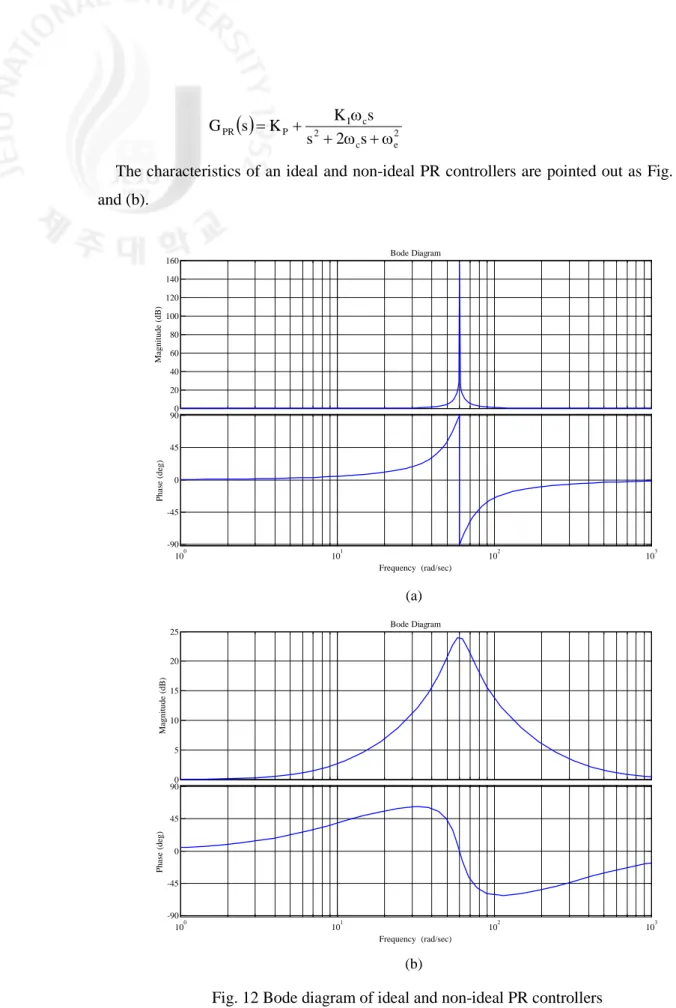
Then, PR controller, which introduces an infinite gain at a selected resonant frequency for eliminating steady state error, constituted by the proportional regulator and resonant controller. The controller can be used to control the AC signals, thus eliminating the need for coordinate system transformation, and these advantages make it suitable for the power quality control applications with high performance.
The PR controller is defined as:
( )
2 e 2 I P PR s s K K s G ω + + = (53)To avoid stability problems associated with an infinite gain, a non-ideal PR controller can be used instead of, and its gain is now finite. The non-ideal PR controller is shown in (54):
0 20 40 60 80 100 120 140 160 Magnitude (dB) 100 101 102 103 -90 -45 0 45 90 P hase (deg) Bode Diagram Frequency (rad/sec) 0 5 10 15 20 25 Magnitude (dB) 100 101 102 103 -90 -45 0 45 90 Phase (deg) Bode Diagram Frequency (rad/sec)
( )
2 e c 2 c I P PR s 2 s s K K s G ω + ω + ω + = (54)The characteristics of an ideal and non-ideal PR controllers are pointed out as Fig. 12(a) and (b).
(a)
Fig. 12 Bode diagram of ideal and non-ideal PR controllers (KP = 1, KI = 30, f = 60 Hz, ωc = 10 rad/s)
(a) Ideal – (b) Non-ideal
Bode Diagram Frequency (rad/sec) -100 -80 -60 -40 -20 0 M a gni tude ( dB ) 102 103 -90 -45 0 45 90 P h as e ( d eg )
Beside the ability of combining in PR controller, the resonant controller can also be used independently as a selective harmonic filter, called by resonant filter, to extract harmonic components from disturbed sources and compensate for. The transfer function of a non-ideal harmonic filter design to compensate for the 3rd, 5th, 7th harmonics is given as:
( )
∑
( )
= + ω + ω ω = 7 , 5 , 3 h 2 e c 2 c Ih h h s 2 s s K 2 s G (55)An interesting feature of the resonant filter is that it does not affect the dynamics of the output signal, including magnitude and phase. The bandwidth of the resonant filter is tuned by ωc. A small value of ωc will give to a narrow resonant peak which leads to more exact
output signal. However, using a smaller ωc will make the filter more sensitive to frequency
variations and the output signal will be more oscillated. Fig. 13 shows results for using the resonant filters to extract harmonic components of 3rd, 5th, 7th from disturbed current.
3.2 Rotor side converter
3.2.1 The operation of RSC under unbalanced gird voltage
ωc = 1 rad/s
ωc = 10 rad/s
Fig. 13 Resonant filter of the 3rd, 5th, 7th harmonics (KIh = 1, ωc = 1 rad/s and ωc = 10 rad/s)
Under unbalanced stator voltage supply, the stator and rotor voltage, current and flux may all contain both positive and negative sequence components.
Fig. 14 shows the spatial relationships between the stationary (αβ)s reference frame, the
rotor (αβ)r reference frame rotating at the speed of ωr, and the (dq) +
and (dq)- reference frames rotating at the angular speed of ωs and -ωs, respectively. As shown, the d
+
axis of the (dq)+ reference frame is fixed to the positive sequence stator flux. According to Fig. 14, the transformation of vector F between (αβ)s(αβ)r, (dq)+, (dq)- reference frames are given by
( ) ( ) r r r s s j j j e F e F e F Fαβ = + θ = − −θ = αβ θ (56) where θs = ωst and θr = ωrt. F vector represents the voltage, current and flux and superscripts
+, - represent the positive and negative synchronous reference frames, respectively.
According to Fig. 14 and (56), F vector can be expressed in the terms of their respective positive and negative sequence components in the positive and negative reference frames as
s j 2 e F F F F F+ = ++ + −+ = +++ −− − θ (57)
Under unbalanced grid voltage conditions, as shown [11], the stator active and reactive powers can be expressed by
+ + − = + s s s s V Iˆ 2 3 jQ P (58)
( )
( )
( )
s scos2( )
s 2 sin s 0 s s s 2 cos s s 2 sin s 0 s s 2 cos . Q 2 sin . Q Q Q 2 cos . P 2 sin . P P P θ + θ + = θ + θ + = (59) whereFig. 14 Relationships between the (αβ)s, (αβ)r, and the (dq)+ and (dq)- reference d- α αr d+ q- β q+ ωs ωr θr -θs=-ωst ψs+ F θs=ωst -ωs
ψ − ψ ψ − ψ − ψ − ψ ψ − ψ ψ − ψ ψ ψ − ω = − − − − + + + + + + + + − − − − + + + + − − − − − − − − + + + + rq rd rq rd sq sd sq sd sd sq sd sq sd sq sd sq s s m 2 cos s 2 sin s 0 s I I I I . L 2 L 3 Q Q P (60) − ψ ψ ψ ψ ψ − ψ ψ ψ − ψ ψ ψ ψ ψ ψ ψ − ψ − ω = − − − − + + + + − − − − + + + + + + + + − − − − + + + + − − − − − − − − + + + + rq rd rq rd m sq sd sq sd sd sq sd sq sq sd sq sd sq sd sq sd s s 2 cos s 2 sin s 0 s I I I I L . L 2 3 P P Q (61)
From (59), we can see that the stator power contains both DC and AC components. The AC component will cause the power oscillation with the frequency of 2ωs.
According to Fig. 7, the electromagnetic power is expressed by the sum of the power outputs generated by the equivalent voltages jωsψs and j(ωs – ωr)ψr as [12]
(
)
[
]
[
]
( )
s ecos2( )
s 2 sin e 0 e r s r s m r r r s s s s e 2 cos . P 2 sin . P P Iˆ . j Re L L 2 3 Iˆ . j Iˆ . j Re 2 3 P θ + θ + = ψ ω = ψ ω − ω + ψ ω − = + + + + + + (62) where ψ ψ − ψ ψ − ψ − ψ − ψ ψ ψ ψ − ψ ψ − ω = − − − − + + + + + + + + − − − − + + + + − − − − − − − − + + + + rq rd rq rd sd sq sd sq sq sd sq sd sd sq sd sq s r m 2 cos e 2 sin e 0 e I I I I . L 2 L 3 P P P (63)The electromagnetic torque of DFIG can be calculated as
ω = P 2 P T r e e (64)
where P is the number of poles.
The active power output from the rotor to the RSC can also be calculated based on the stator output active power and the power imported from the rotor shaft as
(
)
(
)
( )
(
)
( )
( )
s rcos2( )
s 2 sin r 0 r s 2 cos s 2 cos e s 2 sin s 2 sin e 0 s 0 e s e r 2 cos . P 2 sin . P P 2 cos P P 2 sin P P P P P P P θ + θ + = θ − + θ − + − = − = (65)3.2.2 Proposed control strategy for RSC
The control objective of the RSC control is to mitigate the oscillation in the stator active power and the rotor currents during the voltage unbalance.
According to (59), the stator active power oscillation can be eliminated by making Pssin2 =
0 and Pscos2 = 0. Alternatively, the torque pulsation can be eliminated by ensuring Pesin2 = 0
and Pecos2 = 0. However, this computation is difficult because it requires the measurement of
both the stator flux linkage and the positive sequence reference rotor currents [9], [11]. Meanwhile, to separate positive and negative sequence variables, two reference frame are used, namely, the synchronous reference frame (dq)+ and negative synchronous reference frame (dq)- as shown in Fig. 14. The control diagram using the synchronous and negative synchronous reference frame is depicted in Fig. 15.
In Fig. 15, the positive and negative sequence components in the rotor currents are extracted through (dq)+ and (dq)- reference frame transformation. Low pass filters (LPFs) are used to get DC components in each reference frame. However, these filters introduce time delay and deteriorate control performance.
To overcome this problem, a PR controller in the stationary reference frame (αβ) is used and only the rotor currents are measured. The measurements will be transferred to (αβ) frame. The rotor currents in (αβ) frame will only have components with a frequency of ωs under
unbalanced grid voltage conditions [17]. PR controllers are effective to bring the rotor currents to its reference sinusoidal waveforms. Therefore, the controller will mitigate the negative sequence currents in the rotor circuits. The proposed control strategy for the RSC is
PI PI PI PI + + -+ -+ Vdr∗ Vqr∗ Iqr +∗ Iqr Idr +∗ Idr Vdr+ LPF LPF LPF LPF Iar Ibr Icr abc dq dq+ dq- Idr+ -+ Idr −−∗ Iqr+ -+ Iqr −−∗ Idr −− Iqr −− dq- dq+ abc dq + + Vqr+ Vdr- Vqr- Var Vbr Vcr
shown in Fig. 16.
In Fig. 16, the transfer function in the block PR is:
( )
2 e 2 I P PR s s K K s G ω + + =and the back electromagnetic forces (back EMF) Vd and Vq are:
Vd = -(ωs – ωr) ψqr; Vq = (ωs – ωr) ψdr
3.3 Grid side converter
3.3.1 The operation of RSC under unbalanced gird voltage
Similar to RSC, the GSC can be analyzed in the synchronous reference frame where the d-axis is fixed to the grid AC voltage.
From equation (46) and (47), we can get:
f s g g s f f g L V V I j L R dt dI − + ω + − = (66)
Under unbalanced voltage conditions, (66) will be separate into the synchronous reference frame (dq)+ and negative synchronous reference frame (dq)-.
By neglecting the Rf, the active and reactive power output from the GSC to the network
can be expressed as:
( )
( )
( )
g gcos2( )
g 2 sin g 0 g g g 2 cos g g 2 sin g 0 g g 2 cos . Q 2 sin . Q Q Q 2 cos . P 2 sin . P P P θ + θ + = θ + θ + = (67) whereFig. 16 Proposed control strategy for RSC
PI -+ PI -+ PR -+ PR -+ + + + + Vdr∗ Vqr∗ Iqr∗ Ps∗ Ps Iβr Vβr Idr∗ Qs∗ Qs Iαr Vαr Iβr∗ Iα r∗ Vq Vd dq αβ αβ dq dq abc θsl PWM Gate θsl θsl
− − − − − − − = − − − − + + + + + + + + − − − − + + + + − − − − + + + + − − − − + + + + − − − − − − − − + + + + − − − − + + + + gq gd gq gd sd sq sd sq sq sd sq sd sq sd sq sd sd sq sd sq sd sq sd sq sq sd sq sd 2 cos g 2 sin g 2 cos g 2 sin g 0 g 0 g I I I I . V V V V V V V V V V V V V V V V V V V V V V V V 2 3 Q Q P P Q P (68)
The dc-link voltage can be express by:
(
)
(
)
[
( )
( )
( )
]
( )
( )
( )
[
]
(
)
(
) ( )
(
ecos2 scos2 gcos2) ( )
gg 2 sin g 2 sin s 2 sin e 0 g 0 s 0 e g 2 cos g s 2 cos s s 2 cos e g 2 sin g s 2 sin s s 2 sin e 0 g 0 s 0 e g s e g r dc dc 2 cos P P P 2 sin P P P P P P 2 cos . P 2 cos . P 2 cos . P 2 sin . P 2 sin . P 2 sin . P P P P P P P P P V dt dV C θ − + − + θ − + − + − − = θ − θ − θ + θ − θ − θ + − − = − − = − = (69)
Under unbalanced grid voltage, the (69) is important to show that the oscillating term of the dc-link voltage is caused by the oscillating term of electromagnetic power, stator power, and grid power.
3.3.2 Non-linear load
The most common linear loads in the power electronics system are resistors, inductors and capacitors. The most common non-linear loads are diode rectifier, thyristor chopper, arc furnace, and switching mode power supply. A linear load could be defined as a linear relationship between the voltage across and the current through the load or their derivatives. Although there is no explicit mathematical description for nonlinear loads, they could be described as “a load that draws a non-sinusoidal current wave when supplied by a sinusoidal voltage source”.
Under non-linear load conditions, according to [16], the network currents will contain the high order harmonic components of 5th, 7th... These harmonics have several undesirable impacts on the source and other loads connected to the same source, including: distorted source voltage, overheating transformers, system oscillation… Therefore, it is necessary to eliminate the harmonic components from non-linear load.
A non-linear load with the three-phase diode rectifier is shown in Fig. 17. It can be seen from Fig. 17 that the network current is distorted – similar to a quasi-square waveform with two humps on the top.
3.3.3 Proposed control strategy for GSC
The control objective of the GSC control is to keep the dc-link voltage constant under unbalanced grid voltage conditions and compensate harmonic components of the network currents.
According to (69), the oscillating term of the dc-link voltage is caused by the oscillating term of electromagnetic power, stator power, and grid power. At the rotor side, the oscillation of rotor currents and electromagnetic toque is eliminated. Thus, the oscillation of Pe and Ps is
also eliminated. Ultimately, the dc-link voltage pulsation will be eliminated by making Pgsin2 R L IaL IbL IcL Vat Vbt Vct 5th 7th 11th 13th 17th 19th 23th 25th 29th 31th
Fig. 17 Non-linear load with the three-phase diode rectifier (a) Power circuit, (b) Phase A current, (c) FFT of phase A current
(a)
(b)
= -Pesin2 + Pssin2 = 0 and Pgcos2 = -Pecos2 + Pscos2 = 0. Similar to RSC control, it also requires
the measurement the grid voltage and the positive sequence reference grid currents and its decomposition in (dq)+ and (dq)- frame.
In proposed control strategy, a PR current controller in stationary reference frame (αβ) is applied into GSC to suppress negative sequence components in the grid currents. Consequently, the ripple in the dc-link voltage will be mitigated. The proposed control strategy for the GSC is shown in Fig. 18.
In case of non-linear load, a resonant filter is proposed to extract the harmonic components in non-linear load currents and compensate to the network. Therefore, the high order harmonic components in the network currents are suppressed. A current control loop is added to the GSC control as Fig. 18 and the principle of harmonic compensation for non-linear load is presented as Fig. 11.
Ultimately, SPWM technique [18] is also applied into both RSC and GSC to eliminate harmonics that is generated from both the rotor side converter and the grid side converter.
In Fig. 18, the back electromagnetic forces (back EMF) Vd1 and Vq1 are:
Vd1 = -ωsLfIqg; Vq1 = ωsLfIdg
Fig. 18 Proposed control strategy for GSC
PI -+ PI -+ PR -+ PR -+ + + + + θg θg Vd1∗ Vq 1∗ Iqg∗ Vdc∗ Vdc Iβg Vβg Idg∗ Qg∗ Qg Iαg Vαg Iβg∗ Iα g∗ Vq1 Vd1 dq αβ αβ dq dq abc θg PWM Gate Iαh Iβh + +
IV. Simulation results
Simulation results with the proposed control strategy are carried out by using Psim simulation program for 2MW DFIG. The parameters of the DFIG, wind turbine and the non-linear load are given in Appendix. The nominal dc-link voltage is set at 1200V and the switching frequencies for both grid side and rotor side converters are 5 kHz.
4.1 DFIG normal operation
In normal operation, the aim of the rotor side converter controller is to control active and reactive power independently. As mentioned before, the stator active and reactive power can be controlled by using the impressed rotor currents in the stator flux reference frame. Therefore, the stator active power control is achieved by controlling the rotor current q component Iqer orthogonal to the stator flux, while the stator reactive power control is
achieved by controlling the rotor current d component Ider aligned to the stator flux.
Fig. 19 illustrates the control of the active power on the stator side when a step in the reference active power signal Ps_ref on the stator side is imposed from 2 MW to 1 MW, while
the reference reactive power signal Qs_ref is remained unchanged at zero.
In Fig. 19, it can be seen that the stator active power displays a good dynamic performance. There is a little coupling with the stator reactive power control in the transient response. However, in the steady state the stator reactive power is not affected by the stator active power step, as it is back to its reference value. As expected, the step in the reference of the stator active power is reflected only in the q component and not in the d component of the rotor current, as the stator reactive power is controlled by the d component.
In DFIG control, the reference active power is provided by a maximum power tracking depending on the actual generator speed, which assures operation with maximum aerodynamic efficiency. During normal operation the reference reactive power is usually set to zero. For high wind speeds, the speed of the turbine is limited to its rated speed, which implies indirectly that the power is limited to its rated value, too. The operations of DFIG in case of low and high wind speed are depicted in Fig. 20 and Fig. 21.
In Fig. 20, at the low wind speed range, the wind turbine operates at power optimization mode, where the speed controller is passive, keeping the pitch angle to the optimal value (theta = 0). Meanwhile, the power controller controls the stator active power Ps to its
reference signal Ps_ref provided by the maximum power tracking. Therefore, the generator
(a)
(b)
(c)
(d)
Fig. 19 Decoupled control of stator active and reactive power
(a) The reference and actual value of the stator active power, (b) The reference and actual value of the stator reactive power, (c) The reference and actual value of the q component of the rotor current, (d) The reference and actual value of the d component of the rotor current.
speed is adapted to the wind speed, in such a way that it is extracted maximum power out of wind. (c) (d) (e) (f) (a) (b)
Fig. 20 The operation of DFIG in case of low wind speed
(a) Wind speed, (b) pitch angle, (c) Rotor speed, (d) The reference and actual value of the stator active power, (e) The active power from grid side converter, (f) The total active power and the stator active power.
Following Fig. 21, at the high wind speed range, the wind turbine operates at power limitation mode, where both speed controller and power controller are active. The speed
(c) (d) (e) (f) (a) (b)
Fig. 21 The operation of DFIG in case of high wind speed
(a) Wind speed, (b) pitch angle, (c) The reference and actual value of the rotor speed, (d) The reference and actual value of the stator active power, (e) The active power from grid side converter, (f) The total active power and the stator active power.
controller keeps rotor speed at nominal speed of Nrm = 1950 rpm and supplies a variable
pitch angle (theta>0). At the same time, the stator active power is controlled to rated value of 2 MW.
Notice in Fig. 20 and Fig. 21 that during the low wind speed operation (the rotor speed is lower than the synchronous speed) the power delivered to the network Pt is less than that
delivered by the stator active power Ps, as in the rotor circuit the power is flowing from the
network to the rotor via power converter (Pg >0). Meanwhile, in the high wind speed
operation (the rotor speed is higher than the synchronous speed), the power delivered to the network is higher than that delivered from the stator because of the power contribution from the rotor. The rotor power flows from the rotor to the network (Pg>0).
The aim of the grid side converter controller for normal operation is to maintain the dc-link capacitor voltage and to guarantee a converter operation with unity power factor. Similar to RSC, the dc-link voltage and power factor on the grid side can be controlled by using the grid currents in the grid voltage reference frame. Thus, the dc-link voltage control is achieved by controlling the grid current q component Iqeg orthogonal to the grid voltage,
while the power factor control is achieved by controlling the grid current d component Ideg
aligned to the grid voltage.
Fig. 22 DC-link voltage control
(a) The reference and actual value of dc-link voltage, (b) The reactive power from grid side converter, (c) The d and q components of the grid current.
(a)
(b)
Fig. 22 shows that the dc-link voltage almost keeps at its reference value 1200 V, while the reactive power from grid side converter is zero.
The overall normal operation of DIFG at steady state is presented in Fig. 23. It is important that the rotor voltage is always smaller than the stator voltage (Vas > Var) because
the ratio between the turn of stator winding and the turn of rotor winding. At anytime, the reactive power is controlled to zero (Qs = 0, Qg = 0).
Fig. 23 The overall normal operation of 2MW DIFG at steady state
(c)
(d)
(e)
(a)
Fig. 23 The overall normal operation of 2MW DIFG at steady state (cont) (h) (i ) (j ) (k) (f) (g) (l )
4.2 DFIG operation with non-linear load
The aim of DFIG control under non-linear load is to eliminate the high order harmonic components of the network current, which is supplied from non-linear load. The simulation is carried out when DFIG operates at conditions of rated power 2 MW and nominal rotor speed 1950 rpm. The non-linear load of 80 kW is connected to the network at 3.5s. A load variation from 80 kW to 120 kW is performed at 4s. The non-linear load is removed at 4.5s. The simulation results are shown as Fig. 24.
(c)
(d)
(e)
(a)
(b)
It can see that almost harmonic components of the network currents are effectively eliminated in case of non-linear load of 80 kW and 120 kW as Fig. 24(d) and Fig. 24(h).
(g ) (h ) (i ) (f )
Fig. 24 Dynamic responses of system under non-linear load (cont) (a) the non-linear load current IL
- With non-linear load of 80 kW during 3.5s to 4s:
(b) the Fast Fourier Transform (FFT) of IL, (c) the FFT of network current without
compensating harmonics, (d) the FFT of network current with compensating harmonics, (e) the FFT of network current without applying non-linear load.
- With non-linear load of 120 kW during 4s to 4.5s:
(f) the Fast Fourier Transform (FFT) of IL, (g) the FFT of network current without
compensating harmonics, (h) the FFT of network current with compensating harmonics, (i) the FFT of network current without applying non-linear load.
4.3 DFIG operation under unbalanced grid voltage condition
The purpose of DFIG control under unbalanced grid voltage is to eliminate the oscillation in the stator active power, the electromagnetic torque, and the dc-link voltage. Test on the proposed control strategies are carried out under a steady state unbalanced grid voltage of around 3.5%. The voltage unbalance appears at 6.5s and removes at 7s.
The simulation results of the DFIG operation under unbalanced grid voltage condition are presented in Fig. 25. With the proposed PR control strategy, the negative sequence current components can be effectively mitigated as Fig. 25(d), (e). The negative sequence components are shown as the high frequency AC component in the synchronous reference frame. Consequently, the stator and rotor currents in (abc) frame are approximate balance as Fig. 25(a). As a result, the oscillation in the stator active power and torque are significantly reduced and the simulation results are shown in Fig. 25(f), (h). The dynamic response of the link voltage is shown in Fig. 25(i). It is seen that due to the PR current controllers, the dc-link voltage oscillations are well mitigated. Overall the simulation results show that the simple PR current controllers that are applied into DFIG control can effectively reduce the oscillation in the stator active power, torque and the dc-link voltage and the GSC control can also use as a Statcom to compensate harmonic currents from non-linear load.
Fig. 25 Simulation results under transient unbalanced grid voltage of 3.5% during 6.5-7s
(c)
(a)
Fig. 25 Simulation results under transient unbalanced grid voltage of 3.5% during 6.5-7s (cont)
(a) the stator current, (b) the rotor current, (c) the rotor voltage, (d) the stator dq-axis current, (e) the rotor dq-axis current, (f) the stator active power, (g) the grid active power, (h) the electromagnetic torque, (i) the dc-link voltage
(f) (g) (h) (d) (e) (i )
V. Conclusion
This thesis has presented the modeling of the 2 MW DFIG based on wind energy system and its operation. The model of wind turbine has been first analyzed. The method applied into wind turbine control is maximum power point tracking method to extract maximum power from given wind speeds. The operation conditions of DFIG have been then depicted including normal operation, operation under voltage unbalance, operation with non-linear load.
Under normal operation, the main aim control is to achieve optimal power and keep dc-link voltage stability.
Under unbalanced grid voltage, the control strategy is to eliminate the oscillations in the rotor currents and the stator active power and the oscillations in the dc-link voltage. The operation of the DFIG during unbalanced grid condition has been analyzed in the synchronous reference frame (dq)+ and negative synchronous reference frame (dq)-. A coordinated control strategy for the RSC and GSC has been proposed. The proportional-resonant current controllers in the stationary frame (αβ) have been applied into both the RSC and the GSC. The main objectives are: the RSC is controlled to mitigate the oscillations in the stator active power and the rotor currents while the GSC is controlled to mitigate ripples in the dc-link voltage.
When a non-linear load is connected to the network, it supplies high order harmonic components to the network current. In this case, the GSC has been controlled as a STATCOM to compensate for these harmonic components. The resonant filters are used to extract the harmonic components and a current control loop is added to the GSC.
Simulation results using Psim simulation program have been presented to verify the effectiveness of the proposed control strategies with reduced oscillations for the stator and rotor current, torque and dc-link voltage.
Appendix
Simulation parameters: Grid Un = 690 V (line-to-line), f = 60 Hz DFIG Pn = 2 MW, P = 4, J = 98.5 kg.m 2 , Rs = 1.1616 mΩ, Rr= 1.307 mΩ, Lσs = 0.05835 mH, Lσr = 0.06286 mH, Lm = 2.496 mH Wind TurbineRated power = 2 MW, Diameter = 75 m, Gearbox = 101.7, air density = 1.225 kg/m3, Maximum power conversion coefficient = 0.4382,
Optimal tip-speed ratio = 6.335, Cut-in/cut-off speed = 4 (m/s)/21 (m/s), Rated wind speed = 11.9 m/s
Non-linear load of 80 kW R1 = 10.82 Ω, L1 =0.01 mH
Non-linear load of 120 kW R2 = 7.22 Ω, L2 =0.02 mH
References
[1] R. Pena, J.C. Clare, and G.M. Asher, “Doubly fed induction generator using back-to-back PWM converters and its application to variable-speed wind energy generation,”
IEE Proc, Vol. 143, No. 3, pp. 231-241, May. 1996.
[2] S. Muller, M. Deicke, and R.W. De Doncker, “Doubly fed induction generator systems for wind turbines,” IEEE Industry application magazine, Vol. 8, No. 3, pp.26-33, Jul/Aug. 2002.
[3] A. Tapia, G. Tapia, J.X. Ostolaza, and J.R. Saenz, “Modeling and control of a wind turbine driven doubly fed induction generation,” IEEE Trans. Energy Conversions, Vol. 18, No. 2, pp. 194-204, Jun. 2003.
[4] J. Morren and S.W.H. de Haan, “Ride through of wind turbines with doubly-fed induction generator during a voltage dip,” IEEE Trans. Energy Conversion, Vol. 20, No. 2, pp. 435–441, Jun. 2005.
[5] T. Sun, Z. Chen, and F. Blaabjerg, “Transient stability of DFIG wind turbines at an external short-circuit fault,” Wind Energy, Vol. 8, No. 3, pp. 345–360, Aug. 2005. [6] F.M. Hughes, O. Anaya-Lara, N. Jenkins, and G. Strbac, “Control of DFIG-based wind
generation for power network support, ” IEEE Trans. Power Syst, Vol. 20, No. 4, pp. 1958–1966, Nov. 2005.
[7] Lingling Fan, S. Yuvarajan, and R. Kavasseri, “Harmonic analysis of DFIG for a wind energy conversion system,” IEEE trans. Energy Convers., Vol. 25, No.1, pp. 181-190, Mar. 2010.
[8] Lingling Fan, R. Kavasseri, Haiping Yin, Chanxia Zhu, and Minqiang Hu, “Control of DFIG for rotor current harmonics elimination,” IEEE.Power & Energy Society General
Meeting, pp. 1-7, Jul. 2009.
[9] Lie Xu and Yi Wang, “Dynamic modeling and control of DFIG-based wind turbines under unbalanced network conditions,” IEEE Trans. Power system, Vol. 22, No. 1, pp. 314-323, Feb. 2007.
[10] Lingling Fan, Haiping Yin, and R. Kavasseri, “Negative sequence compensation techniques of DFIG-based wind energy systems under unbalanced grid conditions,”
Power electronic and machines in wind applications, pp. 1-6, Aug. 2009.
[11] Lie Xu, “Coordinated control of DFIG’s rotor and grid side converters during network unbalance,” IEEE trans. Power electronic, Vol 23, No. 3, pp. 1041-1049, May. 2008. [12] J. Hu and Y. He, “Modeling and enhanced control of DFIG under unbalanced grid
2009.
[13] Lingling Fan, HaipingYin, and ZhixinMiao, “A novel control scheme for DFIG-based wind energy systems under unbalanced grid conditions,” Electric Power Systems
Research, Vol. 81, No. 2, pp. 254-262, Oct. 2010.
[14] R. Pena, R. Cardenas, and E. Escobar, “Control system for unbalanced operation of stand-alone doubly fed induction generators,” IEEE Trans. Energy Convers., Vol. 22, No. 2, pp. 544–545, Jun. 2007.
[15] J. Yao, H. Li, Y. Liao, and Z. Chen, “An improved control strategy of limiting the dc link voltage fluctuation for a doubly fed induction wind generator,” IEEE Trans. Power
Electron, Vol. 23, No. 3, pp. 1205–1213, May. 2008.
[16] A.Gaillard, P. Poure, S. Saadate, and M. Machmoum, “Variable speed DFIG wind energy system for power generation and harmonic current mitigation,” Renewable
Energy, Vol. 34, No. 6, pp. 1545-1553, Jun. 2009.
[17] R. Teodorescu, F. Blaabjerg, M. Liserre, and P.C. Loh, “Proportional-resonant controllers and filters for grid-connected voltage-source converters,” IEE Proc. Electr.
Power Appl., Vol. 153, No. 5, pp. 750-762, Sep. 2006.
[18] Mehmet Yumurtaci, Seydi Vakkas Üstün, Seçil Varbak Neşe, and Hasan Çimen, “Comparison of Output current harmonics of voltage source inverter used different PWM control techniques,” WSEAS transaction on power systems, Vol. 3, No. 3, pp. 695-704, Nov. 2008.