An evaluation of the accuracy of
CAD-CAM-assisted miniscrew surgical guides
from CBCT and digital models
MiJu Bae
The Graduate School
Yonsei University
An evaluation of the accuracy of
CAD-CAM-assisted miniscrew surgical guides
from CBCT and digital models
Directed by Professor JUNG-YUL CHA
A Dissertation Thesis
Submitted to the Department of Dental Science
and the Graduate School of Yonsei University
in partial fulfillment of the
requirements for the degree of
Doctor of Philosophy of Dental Science
MiJu Bae
June 2013
This certifies that the dissertation thesis of
MIJU BAE is approved.
Thesis Supervisor
___________________________
Jung Yul Cha
___________________________
Chung Ju Hwang
___________________________
Hyung Seog Yu
___________________________
Hee Jin Kim
___________________________
Jong Tae Park
The Graduate School
Yonsei University
감사의 글
연구의 시작부터 논문이 완성되기까지 부족한 저에게 격려와 세심한
지도를 베풀어주신 차정열 지도 교수님께 진심으로 감사드립니다. 보다
좋은 논문을 위하여 조언을 아끼지 않으셨던 황충주 교수님, 유형석
교수님, 바쁘신 와중에도 논문의 주제를 구상하고 진행하는데 많은 도움을
주신 김희진 교수님, 박종태 교수님께도 깊이 감사드립니다.
또한 교정학을 공부할 수 있도록 기회를 주시고 많은 가르침을 주신
박영철 교수님, 백형선 교수님, 김경호 교수님, 이기준 교수님, 정주령
교수님, 최윤정 교수님께 감사와 존경의 말씀을 드립니다.
통계 작업에 많은 도움을 주신 연세대학교 원주의과대학 최은희
교수님께 감사드립니다.
수련 생활에 큰 힘이 되어준 의국 동기 고재민, 김영훈, 김성아, 장지성,
정서연과 의국 후배 최승완 선생, 그리고 실험에 도움을 준 뭉해도람
선생에게 감사의 마음을 전합니다.
항상 변함없는 사랑으로 저를 믿고 훌륭하게 길러주신 부모님과 한결
같은 믿음으로 응원해주시는 시부모님, 그리고 사랑하는 가족들에게도 이
자리를 빌어 깊은 감사의 마음을 전합니다.
마지막으로 늘 곁에서 힘이 되어주는 사랑하는 남편과 딸 세아에게
고마운 마음을 전합니다.
2013년 6월 저자 씀
Table of Contents
List of figures ··· ⅲ
List of tables ··· iv
Abstract (English) ··· v
I. Introduction ··· 1
II. Materials and methods··· 5
A. Study materials ··· 5
B. Making and scanning models ··· 5
C. Choosing insertion site and fabricating surgical guides ··· 7
D. Placement of miniscrews ··· 8
E. Analysis of the accuracy of placement··· 9
F. Statistical analysis ··· 10
III. Results ··· 12
A. Interradicular distance of the maxilla ··· 12
B. Deviations between actual and planned miniscrew placements ··· 12
I. Comparisons of control group and using surgical guide group ··· 12
1. Angular deviations ··· 12
2. Distance (coronal, apex) deviations ··· 12
II. Comparisons of control group and using surgical guide group according to 2-orthodontists ··· 12
1. Angular deviations ··· 12
C. Evaluations of relationship between placed miniscrew and root ··· 15
I. Categorized of three classifications ··· 15
IV. Discussion ··· 16
V. Conclusion ··· 22
References ··· 23
List of Figures
Figure 1. Planning procedures for miniscrew implantation. ··· 6 Figure 2. Surgical guide system instruments. ··· 8 Figure 3. Comparison of planned miniscrew placement and actual
miniscrew placement. ··· 9 Figure 4. The relative positions of miniscrews and roots on CBCT images
List of Tables
Table 1. Number of miniscrews used in the surgical guide group and the control group ··· 5 Table 2. Average of minimum interradicular distance between teeth ··· 13 Table 3. Difference in angle and distance between planned and actual
implanted miniscrews ··· 13 Table 4. Comparison of miniscrew placement accuracy by operators in
surgical guide group and control group ··· 14 Table 5. Statistical comparison of miniscrew placement (middle positioned
group) between surgical guide group and control group using
ABSTRACT
An evaluation of the accuracy of
CAD-CAM-assisted miniscrew surgical guides
from CBCT and digital models
The purpose of this study was to evaluate the accuracy of miniscrew placement using CAD-CAM-assisted miniscrew surgical guides (SG) made by fusing CBCT and digital models. Miniscrews were placed in cadaver maxilla using stereolithogragphic CAD-CAM-assisted surgical guides (SG group; n = 25) or periapical X-rays (control group; n = 20). Insertion sites were selected using a 3-dimensional surgical planning program by fusing maxillary digital model images and CBCT images. Deviations between actual and planned placements were measured as 3-dimensional angular deviations and distance (coronal, apical) deviations. The results of the present study were as follows.
1. The mean value of the minimum interradicular distance in the maxilla, as seen in the CBCT axial view, was 2.80 ± 0.67 mm (mean ± SD). 2. A statistically significant difference was detected in the long-axis
angular deviation between the SG group, 3.14°, and the control group, 9.57° (P <0.001).
3. The 3-dimensional linear distance deviations of miniscrews in the SG group were 0.73 mm at the coronal position and 0.73 mm at the apex. For the control group, these values were 1.56 mm, and 1.28 mm, respectively. Statistically significant differences were observed between the SG and control groups for both values (P <0.01).
4. Deviations differed significantly between operators in the control group (P <0.05), but not in the SG group.
5. The SG group had significantly more screws that were classified as middle position than the control group (P <0.05).
Surgical guide accuracy was improved by construction using digital model imaging. Miniscrews were placed more accurately when surgical guides were used than when a direct method was used. The stability of miniscrews was greater when inserted using CAD-CAM-assisted surgical guides than when inserted using X-ray radiographs. The accuracy of miniscrews was independent operator’s skills when using surgical guides. This results were reflected expectation of using surgical guides clinically.
\
Key words: Miniscrew, CAD-CAM-assisted surgical guides, CBCT, Digital models, Linear and angular deviation, Accuracy.
An evaluation of the accuracy of CAD-CAM-assisted
miniscrew surgical guides from CBCT and digital models
MIJU BAE, D.D.S.
Department of Dental Science, Graduate School, Yonsei University
(Directed by Professor Jung Yul Cha, D.D.S., M.S.D., Ph.D)
I. Introduction
Orthodontic miniscrews provide skeletal anchorage with the advantages of being easy to implant and do not require the cooperation of patients. Therefore, the use of skeletal anchorage has increased as they are able to overcome the limitations of conventional orthodontic treatment methods and several studies have reported this(Leung et al., 2008; Livas et al., 2006; Prabhu and Cousley, 2006; Rungcharassaeng et al., 2005). As the use of miniscrews has increased, various studies regarding methods for providing improved stability of miniscrews after or during placement have been published(Kim et al., 2009; Lee et al., 2009; Topouzelis and Tsaousoglou, 2012; Wang et al., 2009).
The most common problem encountered during miniscrew insertion is the lack of precise knowledge of the anatomy of the insertion area. There are several methods that have been described in the literature to enhance the
precision of the insertion of the screws. CBCT based surgical guides are indicated especially in patients with risky anatomical situations or patients in which insertion is difficult(Liu et al., 2010; Morea et al., 2011; Qiu et al., 2012).
The proximity of miniscrew to tooth structures has been reported to be a major risk factor for failure. Kuroda et al. classified the success rates of miniscrews depending on root proximity. In the root contact group, the success rate of implantations in the mandible was low (35.3 %)(Kuroda et al., 2007). Though some authors argue that root surfaces in contact with miniscrews exhibit swift repair and heal almost completely with removal of the miniscrew or orthodontic force(Kadioglu et al., 2008), there are conflicting previous reports that associate root contact with lower miniscrew success rates(Chen et al., 2008; Kuroda et al., 2007; Motoyoshi et al., 2009).
Root contact is most often due to limited interradicular space at the implantation site(Hu et al., 2009; Kim et al., 2011; Kuroda et al., 2007; Monnerat et al., 2009; Poggio et al., 2006). Taking the anatomical interradicular distances and thickness of cortical bone into consideration, orthodontic miniscrews that are 1.2 - 1.6 mm in diameter and 6 - 7 mm in length are recommended(Lim et al., 2008; Poggio et al., 2006). In addition to anatomical factors, root contact that occurs as a result of the skill level of the operator contributes to a decrease in the stability of miniscrews(Park et al., 2010).
To improve the stability and success rate of miniscrews, placement methods that minimize root contact are being developed. The conventional wire-guide method, in which a simple wire is used in conjunction with periapical x-ray radiographs, is often used. Another method, in which miniscrews are placed using a resin splint-type guide that is made from a plaster model, has also been introduced(D’Haese et al., 2010; Horwitz et al., 2009; Park et al,. 2009; Valente et al., 2009).
Recent improvements in 3-dimensional (3D) imaging techniques have provided a means to overcome the limitations of 2-dimensional (2D) images. The positional relationships of roots can only be seen on radiographic images, and it is difficult to predict the accurate location and distance using only 2D X-ray radiographs. However, application of computed tomography (CT) techniques to 3D dental images has made it possible to accurately evaluate the spatial and positional relationships between teeth(Kim et al., 2009; Lee et al., 2009; Lim et al., 2008; Park et al., 2010; Park and Cho, 2009). Methods for the construction of guides for miniscrew placement that use 3D imaging techniques, such as cone-beam CT (CBCT), 3D software, and stereolithography apparatuses have been reported(Suzuki and Suzuki, 2008; Taiji and Yoich, 2010; Xiaojun et al., 2007). However, studies regarding clinically applicable miniscrew surgical guides are still insufficient due to difficulty in minimizing the intraoral size of guides as well as limits to the accurate fabrication of miniscrew surgical guides using 3D images.
Therefore, the purpose of this study was to evaluate the accuracy of the miniscrew placement using CAD-CAM-assisted miniscrew surgical guides that were constructed after planning appropriate insertion sites using 3D images created by fusion of CBCT and digital model images. The stability of miniscrew placement independent of the operator’s skill level when the surgical guide was utilized was also investigated. With the use of CBCT and digital model images, we propose that the resulting miniscrew surgical guides are simpler in design and easier to use clinically.
II. Materials and methods
A.
Study materials
The miniscrews (BMK®, Biomaterials Korea, Seoul, Korea) used in this
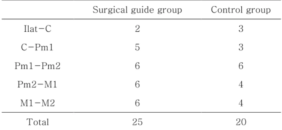
study were cylinder-type miniscrews that were 1.5 mm in diameter and 7.0 mm in length. A total of 45 miniscrews (surgical guide (SG) group n = 25, control group n = 20) were placed. Miniscrews were placed in 12 cadaver maxilla with sound bone quality and soft tissue (Table 1).
B.
Making and scanning models
Impressions of cadaver maxilla were taken in order to make plaster models. Regular and light Aquasil Ultra® (Dentsply, New York, USA) and rubber
Table 1. Number of miniscrews used in the surgical guide group and the control group
Surgical guide group Control group
Ilat-C 2 3 C-Pm1 5 3 Pm1-Pm2 6 6 Pm2-M1 6 4 M1-M2 6 4 Total 25 20
Fig. 1. Planning procedures for miniscrew implantation.: a, CBCT image of maxilla; b, scanned image of maxilla; c, merging of CBCT image and scanned image; d, simulation of miniscrew implantation with the merging 3-D images; e, determination of site of implantation from axial views of reconstructed images; f, determination of site of i m p l an t at i o n f r o m co r o n al v i e w s o f r e co n st r u ct e d i ma g e s
impression materials were used to take impressions. Plaster models were made by pouring New Plastone White® (GC, Tokyo, Japan) into the
impressions. Plaster models were reconstructed into digital models using an Orapix KOD-300 scanner® (Orapix, Seoul, Korea) for fusion with CBCT
images. CBCT Rayscan Symphony® (Ray Inc., Kyungi Province, Korea)
images were obtained for each cadaver maxilla. Default values used for obtaining both pre and post operative images were: 80 kVolt, 10 mA, and 0.5 mm focal spot size (Fig. 1a, b).
C.
Choosing insertion site and fabricating surgical guides
The digital model images were fused with CBCT images using 3D-software (OnDemand 3D®
, Cybermed, Seoul, Korea) (Fig. 1c). A 3D CT image was
constructed using the axial view in the CBCT data. Three points were designated on this image and on the digital model image first, then the surface of a desired site was chosen for fusion of the images. After the interradicular distances were measured on the fused images, miniscrew placement was planned using imaginary miniscrews. When planning miniscrew placement, the relationship between the roots and insertion depth were evaluated in the axial view, though the coronal view and digital models were also taken into consideration. Positive angulation was given to the occlusal plane 4 - 6 mm from the cervical area, according to the ideal insertion location reported in the literature(Lim et al., 2008). Imaginary placement was conducted while allowing for deviation of the insertion angle according to the surface of the insertion site and the slope of the alveolar bone(Lim et al., 2008; Park et al., 2010) (Fig. 1d).
The placement plan file was uploaded onto the dental laboratory’s website for surgical guide fabrication. The surgical guides had a tooth-borne shape and each guide included 4 teeth to ensure stable retention. Surgical guides were made using a CAD-CAM method, and included metal sleeves so that miniscrews could be placed at the planned location (Fig. 2a).
D.
Placement of miniscrews
In the control group, the position of the miniscrews was determined using 2D periapical x-ray radiographs that were reconstructed from CBCT imaging. Control group miniscrews were placed by measuring placement height using a
Fig. 2. Surgical guide system instruments.: a, fabricated surgical guide with a tooth-borne shape, including 4 teeth for stable retention; b, miniscrew pre-drill driver that is 4.0 mm long and is used before miniscrew implantation; c, miniscrew driver that has a step to prevent operators from placing miniscrews too deeply
dental probe via a direct manual method. In the SG group, after placing the surgical guide, pre-drilling was performed using a 1.2 mm width pre-drilling driver. And the miniscrews in this group were placed using a miniscrew driver that was guided by the surgical guide (Table 1) (Fig. 2 b, c).
Miniscrews were placed by 2 orthodontists. CBCT scanning of both the SG group and the control group were obtained after placement.
E.
Analysis of the accuracy of placement
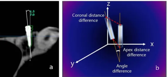
We used the 3D analysis program to determine deviations in angle and location between planned and actual miniscrew placement in real cadaver maxillas. CBCT images taken before and after miniscrew placement were superimposed on the 3D axis. The file containing the planned miniscrew placement was opened over this superimposed image to compare the locations of the planned and actual miniscrew placements. The angular deviation was measured using the long axis of the miniscrews, and the distance deviation was measured at the coronal and apical areas of the miniscrews(Liu et al., 2010; Morea et al., 2011; Qiu et al., 2012; Valente et al., 2009).
Fig. 3. Comparison of planned miniscrew placement and actual miniscrew placement.: a, angular deviation was measured along the long axis of miniscrews; b, distance deviation in 3-D space was measured at the coronal and apex areas of the miniscrews
In the CT co-ordinate system, the dx value indicates the depth of the miniscrew, the dy value indicates the mesio-distal location, and the dz value indicates the vertical position of miniscrews. These values are reported as a sum value that was converted to a linear distance in 3D space (Fig. 3).
After placement, miniscrews were categorized into one of three classifications. These classifications were: middle position, wherein miniscrews were placed in between the roots of the tooth; root contact, wherein miniscrews were placed in contact with the roots of the tooth (invading the periodontal ligament space); and root damage, wherein miniscrews were placed so that they damaged the roots, as indicated by the CBCT axial view. The frequencies of these classifications were compared between experimental groups.
F.
Statistical Analysis
Each variable was measured twice, with 2 weeks between each measurement, and there was no significant difference between measurements (P >0.05). The height and angle of miniscrew insertion and the minimum interradicular distance are reported as means and standard deviations. Deviations between the planned and actual miniscrews are reported as medians (minimum, maximum) because the deviations for neither the SG group nor the control group were normally distributed. In order to find the differences in angle and location of miniscrew placements as well as
differences between operators within the control and SG groups, Wilcoxon two-sample tests were performed using nonparametric Wilcoxon scores (rank sums). Group differences in classification frequency of root proximity were determined to be significant if Fisher’s exact test yielded P <0.05.
III. Results
The mean value of the minimum interradicular distance in the maxilla, as seen in the CBCT axial view, was 2.80 ± 0.67 mm (mean ± SD) (Table 2).
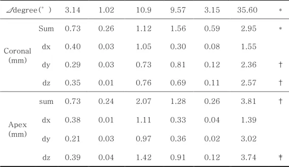
A statistically significant difference was detected in the long-axis angular deviation between the SG group, 3.14°(1.02, 10.9), and the control group, 9.57 ° (3.15, 35.60) (P <0.001). The 3D linear distance deviations of miniscrews in the SG group were 0.73 mm (0.26, 1.12) at the coronal position and 0.73 mm (0.24, 2.07) at the apex. For the control group, these values were 1.56 mm (0.59, 2.95), and 1.28 mm (0.26, 3.81), respectively. Statistically significant differences were observed between the SG and control groups for both values (P <0.01).
The dx, dy, and dz deviation values in the SG group at the apex were 0.38 mm (0.01, 1.11), 0.21 mm (0.03, 0.97), and 0.39 mm (0.04, 1.42), respectively. We found no statistically significant differences in dx and dy values between the planned and actual placements (Table 3).
The coronal dz deviation values in the SG group and the coronal sum, dx, dy, and apex dy deviation values in the control group differed significantly between operators (Table 4).
Table 2. Average of minimum interradicular distance between teeth (mm)
Miniscrew implantation area
Total
Ilat-C C-Pm 1 Pm 1-Pm 2 Pm 2-M 1 M 1-M 2
Mean SD Mean SD Mean SD Mean SD Mean SD Mean SD
2.43 0.20 3.00 0.87 2.89 0.51 2.96 0.89 2.62 0.48 2.80 0.67
Ilat, lateral incisor; C, canine; Pm, premolar; M, molar
Table 3. Difference in angle and distance between planned and actual implanted miniscrews
Surgical guide Control
Sig.
Median Minimum Maximum Median Minimum Maximum
Δdegree(°) 3.14 1.02 10.9 9.57 3.15 35.60 * Coronal (mm) Sum 0.73 0.26 1.12 1.56 0.59 2.95 * dx 0.40 0.03 1.05 0.30 0.08 1.55 dy 0.29 0.03 0.73 0.81 0.12 2.36 † dz 0.35 0.01 0.76 0.69 0.11 2.57 † Apex (mm) sum 0.73 0.24 2.07 1.28 0.26 3.81 † dx 0.38 0.01 1.11 0.33 0.04 1.39 dy 0.21 0.03 0.97 0.36 0.02 3.02 dz 0.39 0.04 1.42 0.91 0.12 3.74 ‡ *P <0.001, †P <0.01, ‡P <0.05
Table 4. Comparison of miniscrew placement accuracy by operators in surgical guide group and control group
Surgical guide
Sig.
Operator 1 Operator 2
Median Minimum Maximum Median Minimum Maximum
Δdegree(°) 4.20 1.43 8.08 2.47 0.46 11.51 Coronal (mm) sum 0.58 0.22 1.00 0.80 0.44 1.12 dx 0.37 0.01 0.95 0.55 0.10 1.06 dy 0.32 0.01 0.74 0.26 0.01 0.70 dz 0.13 0.01 0.58 0.45 0.13 0.82 † Apex (mm) sum 0.55 0.20 1.49 0.82 0.36 2.14 dx 0.22 0.01 0.91 0.48 0.01 1.16 dy 0.19 0.02 0.60 0.28 0.03 0.98 dz 0.35 0.00 1.43 0.40 0.08 1.88 *P <0.001, †P <0.01, ‡P <0.05 Control Sig. Operator 1 Operator 2
Median Minimum Maximum Median Minimum Maximum
Δdegree(°) 8.97 4.53 35.61 9.79 2.91 22.21 Coronal (mm) sum 0.96 0.57 1.75 1.82 2.95 2.95 ‡ dx 0.22 0.04 0.77 0.45 1.60 1.60 ‡ dy 0.32 0.10 0.93 1.33 2.42 2.42 † dz 0.87 0.18 1.70 0.66 2.60 2.60 Apex (mm) sum 0.99 0.25 3.83 1.62 3.65 3.65 dx 0.36 0.05 1.16 0.30 1.43 1.43 dy 0.23 0.02 0.70 0.63 3.04 3.04 ‡ dz 0.90 0.02 3.77 1.04 2.34 2.34 *P <0.001, †P <0.01, ‡P <0.05
Table 5. Statistical comparison of miniscrew placement (middle positioned group) between surgical guide group and control group using Fisher’s
exact-test
Fig. 4. The relative positions of miniscrews and roots on CBCT images taken after miniscrew insertion.: a, miniscrews well-placed between roots; b,
placement of miniscrews causing damage to roots
After implantation, 84.0 % of screws in the SG group were classified as middle position and 16.0 % as root contact. There no screws classified as root damage in the SG group. In the control group, 50.0 % of screws were classified as middle position, 30.0 % as root contact, and 20.0 % as root damage. The SG group had significantly more screws that were classified as middle position than the control group (P <0.05) (Fig. 4).
Surgical guide(n=25) Control(n=20) P value Middle position 21 (84.0 %) 10 (50.0 %) 0.016*
IV. Discussion
A direct manual method is commonly used for the placement of miniscrews, and various methods for minimizing root damage have been suggested. In the direct manual method, root damage is reported to be reduced when insertion is 4 - 6 mm below the alveolar crest(Lim et al., 2008). A vertical insertion angle of 30 - 45°is advantageous(Lim et al., 2008), and distal tilting of 10 - 20°is reported to be safe(Park et al., 2010). However, according to a study by Kuroda et al.(Kuroda et al., 2007), contact with or damage to anatomical structures around the roots of teeth occurred in 47.4 % of maxillary and 48.3 % of mandibular miniscrews that were placed using a direct manual method. Therefore, orthodontic miniscrews inserted using the direct manual method can cause unexpected damage to anatomical structures around teeth because this method depends on the senses of the operator, whose vision may be limited.
3D image programs are already being used to determine accurate positioning and to make surgical guides for prosthetic implantation. CT scans are taken for evaluation of alveolar bone condition, and the positions of implants are determined based on 3D digital images that are reconstructed from CT data(D'Haese et al., 2012; Horwitz et al., 2009; Valente et al., 2009; Xiaojun et al., 2007). In a previous ex vivo study that used CAD-CAM
implant surgical guides, the mean deviation angle between planned and actual implants was 3.9°and the distance deviation at the miniscrew apex was 0.90 mm(D'Haese et al., 2012). In an in vivo experiment, the mean deviation angle was 3.54°and the distance deviation at the miniscrew apex was 1.64 mm (D'Haese et al., 2012).
Reconstructing 3D digital images from CT images alone is associated with several problems, such as distortion of the CT image or the formation of artifacts due to a metal substance in the mouth or a beam-hardening effect. The use of digital model images that are comprised of scanned images of plaster models, in combination with CT images, is reported to overcome these problems(Taiji and Yoich, 2010).
In this experiment using cadavers, the accuracy of placement of orthodontic miniscrews was improved when compared to previous reports measuring the difference between planned and actual placement of prosthetic implants. The angular deviation was 3.14°and the linear distance deviation was 0.73 mm coronally and 0.73 mm apically when SGs were used. Because the mean interradicular distance in this experiment was 2.80 ± 0.67 mm, and the diameter of the miniscrews was 1.5 mm, there was an expected 0.6 mm of space between the miniscrew and root to allow for any mesio-distal deviation. In the SG group, the mesio-distal deviation was 0.29 mm coronally and 0.21 mm apically. This suggests that root contact was rare and miniscrews could be stably placed.
Previous experiments comparing surgical guides to other methods of miniscrew placement showed that miniscrews were placed with the narrowest range of deviation when surgical guides were used(Suzuki and Suzuki, 2008). These experiments were limited, however, because miniscrew placement planning, measurement of angular deviation, and measurement of distance deviation were all performed using periapical x-ray images that did not permit a complete understanding of 3D positional relationships. Miniscrews that appear to be invading the root on periapical x-ray images have been found to be placed between roots, without damage to the roots on CBCT images(Kuroda et al., 2007). Therefore, 3D x-ray images are absolutely necessary for accurate evaluation of the insertion position of miniscrews.
The accuracy of miniscrew surgical guides that were made using a 3D planning program based on CBCT images has also been reported elsewhere. Liu et al.(Liu et al., 2010) reported that the angular deviation was 1.2 ± 0.43° and the mesio-distal deviation was 0.42 ± 0.13 mm at the apical area when using SGs. Similarly, Morea et al.(Morea et al., 2011) reported that the angular deviation was 1.76° and the 3D linear distance deviation was 0.86 mm (coronal) and 0.87 mm (apex) using surgical guides. However, the surgical guides that were used in these studies covered more than 2-quadrants, or all of the teeth. And in order to use the surgical guides described in these previous studies, a simpler design and control of artifacts during CT image reconstruction could increase their clinical efficacy.
Conversely, the miniscrew surgical guides used in this experiment aided in more accurate miniscrew placement than reported in previous studies. Furthermore, guide fabrication was simpler as the number of teeth covered could be varied, depending on retention.
When miniscrews were placed by two operators with different levels of experience, there was little difference in the accuracy of placement between the two operators when surgical guides were used. This implies that deviations between operators can be reduced through the use of surgical guides. In the SG group, the insertion height at the coronal area was significantly different between operators. This difference at the coronal area has a low correlation with root contact. In the control group, on the other hand, screws placed by the two operators were significantly different in coronal sum, dx, and dy values and in the apex dy value. The difference in dy value represents a mesio-distal discrepancy that was related to root contact during implantation of miniscrews. Significant differences between groups suggest that the likelihood of root contact depends on the operator’s experience in miniscrew placement using the direct manual method.
In the control group, the percentage of cases classified as root damage or root contact was 50.0 %. This is a high frequency that occurred even though the insertion site was determined using periapical x-rays in advance. Root contact and miniscrew mobility are significantly correlated with miniscrew stability(Wang et al., 2009). In addition, damage to the periodontal ligament
from miniscrews is a typical reason for early loosening of miniscrews, and contact of miniscrews with adjacent structures around the root results in their failure. As the distance between the root and miniscrew decreases to than 0.6 mm, the incidence of root resorption increases, and can progress to bone resorption and ankylosis in severe cases(Lee et al., 2010).
In this current study, CBCT images after placement revealed no root contact or damage by miniscrews in the SG group, and 16.0 % of miniscrews were close to the PDL space. The stability of miniscrews is affected by the positional relationship between the miniscrews and the anatomical structures around roots, and the success rate of miniscrews has been reported to be 90.9 % when surgical guides are used(Miyazawa et al., 2010). Although the long-term stability of miniscrews could not be analyzed in this cadaver study, the success rate of miniscrews placed using surgical guides is expected to be higher than that of miniscrews placed using direct placement methods, because of the lower incidence of root damage that is associated with the use of surgical guides.
When using the direct method, if the interradicular relationship appears clear and the interradicular distance seems sufficient in 2D radiographic images, such as the panoramic or periapical views, miniscrews can be implanted successfully. Furthermore, if miniscrews are placed by an experienced orthodontist, the success rate will probably be higher. However, when 2D images of the desired implantation site do not portray an accurate
interradicular relationship, when the interradicular distance is short, or when there are significant anatomical structures nearby such as the maxillary sinus or nerve canal, 3D imaging, like CBCT, may be necessary in planning miniscrew implantation. Although CBCT imaging is not conventionally prescribed considering the cost and the amount of radiation, it can be a valuable tool for fabricating surgical guides for successful placement of miniscrews when used selectively incases where there are limitations to miniscrew placement. Furthermore, the results of this study indicate that when there are limitations near the insertion site, surgical guides can help to increase the success rate of miniscrews placed regardless of the operator’s skill level.
Placement deviation can occurs while merging CBCT and digital model images or fusing pre and post CBCT images for mechanical errors in 3D program. In order to reduce placement deviation, merging technique should be more precise and SG retention during implantation should be increased so that they are not dislodged as a result of implantation force during placement. The long-term stability of miniscrews also needs to be evaluated in orthodontic patients with miniscrews that were placed using surgical guides.
V. Conclusion
Compared to previous studies, the accuracy of CAD-CAM-assisted surgical guides was improved by using a fusion of CBCT images and digital model images. There was no significant difference between the planned placement and the actual placement of miniscrews using these improved surgical guides.
Miniscrews were placed more accurately when surgical guides were used than when a direct method was used. Statistically significant differences were observed between the surgical guide and control groups for both angular and distance values.
Differences in miniscrew placement between operators significantly decreased when surgical guides were used, as compared to controls. It suggested that the likelihood of root contact depends on the operator’s experience in miniscrew placement using the direct manual method.
Miniscrews placed using surgical guides did not cause damage to surrounding anatomical structures. The SG group had significantly more screws that were classified as middle position than the control group.
Additionally, because of surgical guides combined with CBCT and digital model images were simpler in design and fabrication processes than CBCT based surgical guides, it was expected easier to use clinically.
References
Chen YH, Chang HH, Chen YJ, Lee D, Chiang HH, Yao CC. 2008. "Root contact during insertion of miniscrews for orthodontic anchorage increases the failure rate: an animal study." Clin Oral Implants Res. 19(1):99-106.
D'Haese J, Van De Velde T, Komiyama A, Hultin M, De Bruyn H. 2012. "Accuracy and Complications Using Computer-Designed Stereolithographic Surgical Guides for Oral Rehabilitation by Means of Dental Implants: A Review of the Literature." Clin Implant Dent Relat Res. 14(3):321-335.
Horwitz J, Zuabi O, Machtei EE. 2009. "Accuracy of a computerized tomography-guided template-assisted implant placement system: an in vitro study." Clin Oral Implants Res. 20(10):1156-1162.
Hu KS, Kang MK, Kim TW, Kim KH, Kim HJ. 2009. "Relationships between Dental Roots and Surrounding Tissues for Orthodontic Miniscrew Installation." Angle Orthod. 79(1):37-45.
Kadioglu O, Buyukyilmaz T, Zachrisson BU, Maino BG. 2008. "Contact damage to root surfaces of premolars touching miniscrews during orthodontic treatment." Am J Orthod Dentofacial Orthop. 134(3):353-360.
Kim DH, Park MS, Won SY, Hu KS, Han DH, Kim HJ. 2011. "Alveolar Regions of the Mandible for the Installation of Immediate-Implant Fixtures and Bone Screws of Alveolar Distractors." J Craniofac Surg. 22(3):1056-1060.
Kim SH, Yoon HG, Choi YS, Hwang EH, Kook YA, Nelson G. 2009. "Evaluation of interdental space of the maxillary posterior area for orthodontic mini-implants with cone-beam computed tomography."
Am J Orthod Dentofacial Orthop. 135(5):635-641.
Kuroda S, Yamada K, Deguchi T, Hashimoto T, Kyung HM, Takano-Yamamoto T. 2007. "Root proximity is a major factor for screw failure in orthodontic anchorage." Am J Orthod Dentofacial Orthop. 131(4 Suppl):S68-73.
Lee KJ, Joo E, Kim KD, Lee JS, Park YC, Yu HS. 2009. "Computed tomographic analysis of tooth-bearing alveolar bone for orthodontic miniscrew placement." Am J Orthod Dentofacial Orthop. 135(4):486-494.
Lee YK, Kim JW, Baek SH, Kim TW, Chang YI. 2010. "Root and bone response to the proximity of a mini-implant under orthodontic loading." Angle Orthod. 80(3):452-458.
Leung MT, Lee TC, Rabie AB, Wong RW. 2008. "Use of miniscrews and miniplates in orthodontics." J Oral Maxillofac Surg. 66(7):1461-1466.
Lim JE, Lim WH, Chun YS. 2008. "Quantitative evaluation of cortical bone thickness and root proximity at maxillary interradicular sites for orthodontic mini-implant placement." Clin Anat. 21(6):486-491. Liu H, Liu DX, Wang G, Wang CL, Zhao Z. 2010. "Accuracy of surgical
positioning of orthodontic miniscrews with a computer-aided design and manufacturing template." Am J Orthod Dentofacial Orthop. 137(6):728 e721-728 e710; discussion 728-729.
Livas C, Renkema AM, Kiliaridis S, Katsaros C. 2006. "Bone anchorage in orthodontics. A review." Ned Megazine of Dentistry. 113(3):96-100. Miyazawa K, Kawaguchi M, Tabuchi M, Goto S. 2010. "Accurate pre-surgical
determination for self-drilling miniscrew implant placement using surgical guides and cone-beam computed tomography." Eur J Orthod. 32(6):735-740.
Monnerat C, Restle L, Mucha JN. 2009. "Tomographic mapping of mandibular interradicular spaces for placement of orthodontic mini-implants." Am
J Orthod Dentofacial Orthop. 135(4):428 e421-429; discussion
428-429.
Morea C, Hayek JE, Oleskovicz C, Dominguez GC, Chilvarquer I. 2011. "Precise insertion of orthodontic miniscrews with a stereolithographic surgical guide based on cone beam computed tomography data: a pilot study." Int J Oral Maxillofac Implants. 26(4):860-865.
Motoyoshi M, Ueno S, Okazaki K, Shimizu N. 2009. "Bone stress for a mini-implant close to the roots of adjacent teeth-3D finite element analysis." Int J Oral Maxillofac Surg. 38(4):363-368.
Park HS, Hwangbo ES, Kwon TG. 2010. "Proper mesiodistal angles for microimplant placement assessed with 3-dimensional computed tomography images." Am J Orthod Dentofacial Orthop. 137(2):200-206.
Park J, Cho HJ. 2009. "Three-dimensional evaluation of interradicular spaces and cortical bone thickness for the placement and initial stability of microimplants in adults." Am J Orthod Dentofacial Orthop. 136(3):314 e311-312; discussion 314-315.
Poggio PM, Incorvati C, Velo S, Carano A. 2006. ""Safe zones": a guide for miniscrew positioning in the maxillary and mandibular arch." Angle
Orthod. 76(2):191-197.
Prabhu J, Cousley RR. 2006. "Current products and practice: bone anchorage devices in orthodontics." J Orthod. 33(4):288-307.
Qiu L, Haruyama N, Suzuki S, Yamada D, Obayashi N, Kurabayashi T, et al. 2012. "Accuracy of orthodontic miniscrew implantation guided by stereolithographic surgical stent based on cone-beam CT-derived 3D images." Angle Orthod. 82(2):284-293.
Rungcharassaeng K, Kan JY, Caruso JM. 2005. "Implants as absolute anchorage." J Calif Dent Assoc. 33(11):881-888.
Suzuki EY, Suzuki B. 2008. "Accuracy of miniscrew implant placement with a 3-dimensional surgical guide." J Oral Maxillofac Surg. 66(6):1245-1252.
Taiji S, Yoich K. 2010. "Original computer aided support system for safe and accurate implant placement-Collaboration with an university originated venture company." Japanese Dental Science Review. (59):9. Topouzelis N, Tsaousoglou P. 2012. "Clinical factors correlated with the
success rate of miniscrews in orthodontic treatment." Int J Oral Sci. 10(1038).
Valente F, Schiroli G, Sbrenna A. 2009. "Accuracy of computer-aided oral implant surgery: a clinical and radiographic study." Int J Oral
Maxillofac Implants. 24(2):234-242.
Wang HN, Liu DX, Wang CL, Lu T, Liu H, Wang HL. 2009. "Influence of periodontal ligament injury on initial stability for immediately loaded mini-implant." West China J Stomat. 27(2):224-226, 236.
Xiaojun C, Yanping L, Yiqun W, Chengtao W. 2007. "Computer-aided oral implantology: methods and applications." J Med Eng Technol. 31(6):459-467.
국 문 요 약
CBCT와 Digital model을 이용한
CAD
-
CAM
-
assisted miniscrew surgical guide의
정확성 평가
배미주
연세대학교 대학원 치의학과
(지도교수 차정열)
이 연구의 목적은 CBCT와 디지털 모델을 병합(fusion)하여 제작한 CAD-CAM-assisted 미니스크류 surgical guide를 이용하여 미니스크류를 식립 할 경우 미니스크류 식립 위치의 정확성을 평가하고자 한다.
한국인 시신 12구의 상악골을 대상으로 CAD-CAM-assisted 미니스크류 surgical guide를 이용한 SG군(n=25)과 치근단 방사선 사진을 이용한 대조군 (n=20)으로 나누어 총 45개의 미니스크류를 식립하였다. 상악골의 디지털 모델 영상과 CBCT 영상을 병합(fusion)하여 3차원 surgical planning program을 통하여 미니스크류 식립 위치를 계획하였다. SG군과 대조군에서 각각 실제 식립한 미니스크류와 가상의 미니스크류 간의 각도 편차 및 3차원 거리 편차(coronal, apical)를 각각 측정, 비교하여 다음과 같은 결과를 얻었다. 1. CBCT의 axial상에서 상악 치아의 최소 치근간 거리를 측정한 결과 평균 2.80 ± 0.67 mm 로 나타났다. 2. 미니스크류 장축에 대한 각도 편차는 SG군에서 3.14°, 대조군에서 9.57°로 유의한 차이를 나타내었다 (P <0.001).
3. 3차원 직선 거리 편차는 SG군 coronal에서 0.73 mm, apical에서 0.73 mm 로 측정되었으며, 대조군 coronal에서 1.56 mm, apical에서 1.28 mm 로 측정되었다. 이 둘 사이에 모두 유의한 차이가 관찰되었다 (P <0.01). 4. 대조군의 경우 식립을 시행한 술자 간의 유의한 편차를 나타내었으나 (P <0.05), SG군의 경우 차이를 나타내지 않았다. 5. SG군에서 대조군보다 middle position으로 분류된 미니스크류가 유의하게 더 많았다 (P <0.05). Surgical guide의 정확성은 디지털 모델 이미지를 사용하여 제작한 경우에서 더 향상되었다. 미니스크류는 통상적인 직접 식립법 보다 surgical guide를 사용하였을 경우 더 정확하게 식립되었으며, 이에 따라 미니스크류의 안정성이 증가할 것을 예측할 수 있었다. Surgical guide를 사용한 경우 술자의 숙련도에 따른 미니스크류 식립 정확성의 의존도는 낮아졌으며, 기존 surgical guide에 비해 좀더 간편한 제작 과정과 디자인으로 효율적인 임상 적용을 기대해 볼 수 있었다.
핵심되는 말: 미니스크류, CAD-CAM-assisted surgical guides, CBCT, 디지털 모델, 거리와 각도 편차, 정확성