Highly efficient phosphor-converted white
organic light-emitting diodes with moderate
microcavity and light-recycling filters
Sang-Hwan Cho,1 Jeong Rok Oh,2 Hoo Keun Park, 2 Hyoung Kun Kim,2 Yong-Hee Lee,3 Jae-Gab Lee,4 and Young Rag Do2 *
1Department of Physics, KAIST, Daejeon 305-701, Korea 2Department of Chemistry, Kookmin University, Seoul 136-702, Korea 3
Department of Physics and Graduate School of Nanoscience & Technology (World Class University), KAIST, Daejeon 305-701, Korea
4School of Advanced Materials Engineering, Kookmin University, Seoul 136-702, Korea *[email protected]
Abstract: We demonstrate the combined effects of a microcavity structure
and light-recycling filters (LRFs) on the forward electrical efficiency of phosphor-converted white organic light-emitting diodes (pc-WOLEDs). The introduction of a single pair of low- and high-index layers (SiO2/TiO2)
improves the blue emission from blue OLED and the insertion of blue-passing and yellow-reflecting LRFs enhances the forward yellow emission from the YAG:Ce3+ phosphors layers. The enhancement of the luminous efficacy of the forward white emission is 1.92 times that of a conventional pc-WOLED with color coordinates of (0.34, 0.34) and a correlated color temperature of about 4800 K.
© 2010 Optical Society of America
OCIS codes: (220.0220) Optical design and fabrication; (230.0230) Optical devices; (230.1480)
Bragg reflectors; (230.3670) Light-emitting diodes. References and links
1. C. W. Tang, S. A. Van Slyke, and C. H. Chen, “Electroluminescence of doped organic thin films,” J. Appl. Phys.
65(9), 3610–3616 (1989).
2. C. Adachi, T. Tsutsui, and S. Saito, “Organic electroluminescent device having a hole conductor as an emitting layer,” Appl. Phys. Lett. 55(15), 1489–1491 (1989).
3. S. R. Forrest, M. A. Baldo, and M. E. Thompson, “High-efficiency fluorescent organic light-emitting devices using a phosphorescent sensitizer,” Nature 403(6771), 750–753 (2000).
4. B. W. D’Andrade, and S. R. Forrest, “White Organic Light-Emitting Devices for Solid-State Lighting,” Adv. Mater. 16(18), 1585–1595 (2004).
5. C.-C. Chang, J.-F. Chen, S.-W. Hwang, and C. H. Chen, “Highly efficient white organic electroluminescent devices based on tandem architecture,” Appl. Phys. Lett. 87(25), 253501 (2005).
6. A. Misra, P. Kumar, M. N. Kamalasanan, and S. Chandra, “White organic LEDs and their recent advancements,” Semicond. Sci. Technol. 21(7), R35–R47 (2006).
7. B. C. Krummacher, V.-E. Choong, M. K. Mathai, S. A. Choulis, F. So, F. Jermann, T. Fiedler, and M. Zachau, “Highly efficient white organic light-emitting diode,” Appl. Phys. Lett. 88(11), 113506–113508 (2006). 8. Y. W. Ko, C. H. Chung, J. H. Lee, Y. H. Kim, C. Y. Sohn, B. C. Kim, C. S. Hwang, Y. H. Song, J. Lim, Y. J.
Ahn, G. W. Kang, N. Lee, and C. Lee, “Efficient white organic light emission by single emitting layer,” Thin Solid Films 426(1-2), 246–249 (2003).
9. G. Parthasarathy, G. Gu, and S. R. Forrest, “A Full-Color Transparent Metal-Free Stacked Organic Light Emitting Device with Simplified Pixel Biasing,” Adv. Mater. 11(11), 907–910 (1999).
10. A. Duggal, J. Shiang, C. Heller, and D. Foust, “Organic light-emitting devices for illumination quality white light,” Appl. Phys. Lett. 80(19), 3470–3472 (2002).
11. N. Narendran, Y. Gu, J. P. Freyssinier-Nova, and Y. Zhu, “Extracting phosphor-scattered photons to improve white LED efficiency,” Phys. Stat. Solidi A 202(6), R60–R62 (2005).
12. S.-H. Cho, Y.-W. Song, J.-G. Lee, Y.-C. Kim, J. H. Lee, J. Ha, J. S. Oh, S. Y. Lee, S. Y. Lee, K. H. Hwang, D. S. Zang, and Y. H. Lee, “Weak-microcavity organic light-emitting diodes with improved light out-coupling,” Opt. Express 16(17), 12632–12639 (2008), http://www.opticsinfobase.org/abstract.cfm?URI=oe-16-17-12632.
14. J. R. Oh, S.-H. Cho, Y.-H. Lee, and Y. R. Do, “Enhanced forward efficiency of Y3Al5O12:Ce3+ phosphor from white light-emitting diodes using blue-pass yellow-reflection filter,” Opt. Express 17(9), 7450–7457 (2009), http://www.opticsinfobase.org/abstract.cfm?URI=oe-17-9-7450.
15. S.-K. Kim, B. Yang, Y. Ma, J.-H. Lee, and J.-W. Park, “Exceedingly efficient deep-blue electroluminescence from new anthracenes obtained using rational molecular design,” J. Mater. Chem. 18(28), 3376–3384 (2008). 16. H. A. Macleod, Thin-Film Optical Filters 3rd Edition, Institute of Physics Publishing (2003).
17. A. F. Turner, and P. W. Baumeister, “Multilayer mirrors with high reflectance over an extended spectral region,” Appl. Opt. 5(1), 69–76 (1966).
1. Introduction
Organic light-emitting diodes (OLEDs) have attracted much attention because of their desirable characteristics, including low-power consumption, low driving voltage, wide viewing angle, and fast response [1–3]. Various green, blue, and red OLEDs have been demonstrated, and the commercialization of full-color OLED displays is underway. Recently, white OLEDs (WOLEDs) have also attracted considerable attention for general solid-state lighting applications, backlights for liquid crystal displays, and large-area full color displays by coupling with color filters [4–6].
Methods to generate white light from OLEDs can be broadly classified into three approaches [7]. The first uses a single white emissive layer structure doped with different kinds of emissive materials [8]. While this approach offers easy fabrication but it is difficult to tune the color without affecting device performance. The second uses a vertical/horizontal red-green-blue stacked structure [9]. This stacked OLED is a versatile white OLED (WOLED) that allows for independent tuning of the color mix, thereby providing for color homogeneity and tuning of chromaticity over a wide range. However, manufacture of this structure is complex and it is difficult to achieve color stability due to different aging rates of individual emitters. The last approach employs a blue OLED fabricated on one side of a glass substrate, and color-conversion-materials (CCM) deposited onto the opposite side of the substrate [10]. This phosphor-converted emission method to obtain white emission is already widely used in inorganic GaN-based phosphor-converted LEDs (pc-LEDs). This CCM approach offers a facile fabrication process and can provide better color stability, since the aging rate is determined by only one emitter. However, the low conversion efficiency of the CCM layer prevents real deployment in this area. There are two basic reasons for the low conversion efficiency. One reason is the low absorption efficiency of the CCMs. This is due to inefficient excitation from a broad emission and low device efficiency of the blue OLED source. As previously reported in connection with inorganic pc-white LEDs, the other reason is mainly related to the low forward efficiency of the coated phosphor layer [11]. For the conventional case of a phosphor-converted white organic light-emitting diode (pc-WOLED), half of the phosphor-converted light is emitted directly back into the blue OLED. This results in considerable loss, thus reducing the phosphor conversion efficiency.
In this letter, we demonstrate a highly efficient pc-WOLED combined with both a moderate microcavity structure [12,13] and light-recycling filters (LRFs) [14]. In order to enhance the forward efficiency of a blue OLED and modify the emission spectrum, we insert a single pair of low- and high-index layers (SiO2/TiO2) between indium tin oxide (ITO) and a
glass substrate to serve as a Bragg mirror, thus achieving improved emission characteristics, tunabilty of peak position, and spectral narrowness of blue emission. Furthermore, in order to recycle the backward emission of the YAG phosphor layer into the blue OLED and improve the efficiency of the pc-WOLED, we introduce a shortwave-pass filter [called a light-recycling filter (LRF)] coated glass substrate into the interface between a Y3Al5O12:Ce3+
(YAG:Ce) phosphor layer and a front glass substrate of a blue OLED source. This LRF functions as a window for blue OLED light and a mirror for yellow phosphor emission.
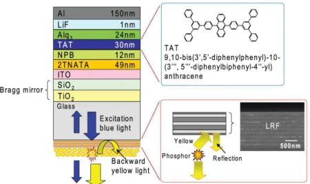
Fig. 1. Schematic representation of the proposed pc-WOLED combined with a microcavity structure and LRF. A single pair of SiO2 and TiO2 inserted in the blue OLED. On the front-side of the blue microcavity OLED, a YAG:Ce phosphor layer coated LRF glass substrate is attached with index matching immersion oil. The enlarged side view shows the mechanism that leads to enhancement of the forward emission from the YAG:Ce yellow phosphor layer and SEM images of the LRF. The upper inset shows the chemical structure of TAT.
2. Results and discussion
A schematic representation of the proposed pc-WOLED is shown in Fig. 1. In this technology, a blue emitting OLED is coupled with a down-converting YAG:Ce yellow phosphor layer. On the front-side of the blue OLED, a phosphor coated plain or LRF glass substrate is attached with index matching immersion oil. The phosphor layers absorb emissions from the blue OLED and emit yellow light according to their intrinsic properties. The mixing of unabsorbed blue emission from the blue OLED and the yellow emission from the phosphors produces white light. In our blue OLED structure, a single pair of low (SiO2) - and high (TiO2)- index
layers is added between ITO and the glass substrate in order to increase the top reflectivity. Recently, our group reported a moderate microcavity OLED containing a single pair of low- and high-index layers with a finely tunable peak position and a bandwidth of EL emission that achieved enhanced external efficiency [12,13].
Both conventional and microcavity blue OLEDs with an active area of 2x2 mm2 were fabricated in the following configurations: ITO (150 nm (conventional OLED), or 80 nm (microcavity OLED))/4,4’,4”-tris(N-(2-naphthyl)-N-phenylamino) triphenylamine [2-TNATA] (49 nm)/N,N’-bis(naphthalen-1-yl)-N,N’-bis(phenyl)benzidine [NPB] (12 nm)/ 9,10-bis(3′,5′-diphenylphenyl)-10-(3′”,5′”-diphenylbiphenyl-4”-yl)anthracene [TAT] (30 nm)/8-hydroxyquinolinealuminium [Alq3] (24 nm)/LiF (1 nm)/Al (150 nm). To fabricate a
moderate microcavity OLED, a single pair of high-index TiO2 (50 nm) and low-index SiO2
(80 nm) thin films were deposited alternatively on glass substrates by e-beam evaporation at 250°C. An ITO layer (80 nm) was then deposited by magnetron sputtering with no intentional heating, and organic layers corresponding to 2-TNATA, NPB, TAT, and Alq3 as well as a LiF
film and aluminum metal cathode were evaporated sequentially to fabricate microcavity devices.
Figure 1 shows the chemical structures of the blue emitting material (TAT) in this experiment. As previously reported [13,15], TAT was synthesized by Boration and Suzuki aryl–aryl coupling reactions. The detailed synthesis route and characterization results of TAT
evaporation at 250°C. The inset in Fig. 1 shows a side-view scanning electron microscopy (SEM) image of a real fabricated LRF dielectric multilayer comprised of modified, alternate TiO2 and SiO2 quarter-wave films of the ninth periods.
YAG:Ce phosphor powders (Nichia Co. Ltd.) were coated on LRF-assisted and plain glass substrates using a sedimentation method. The detailed sedimentation process of the YAG:Ce layer has been reported elsewhere [14]. All the samples in this experiment have the same phosphor density and a sedimented phosphor layer of 3.8 mg/cm2.
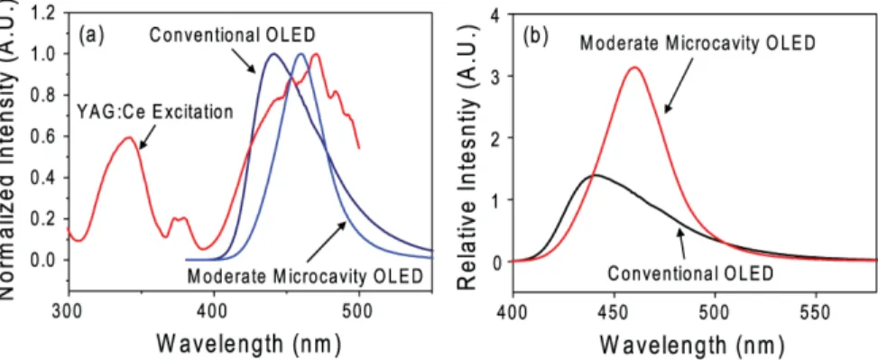
Fig. 2. (a) Normalized EL spectra of a conventional OLED, moderate microcavity OLED, and YAG:Ce excitation spectrum. (b) The relative EL spectra of a conventional OLED and microcavity OLED.
Figure 2(a) shows the normalized electroluminescence (EL) spectra and YAG:Ce excitation peak. The peak position of YAG:Ce excitation is about 470 nm; however the peak wavelength of the conventional blue OLED is about 440 nm. Hence, blue emission inefficiently overlaps with excitation of YAG:Ce phosphor. In the case of the moderate microcavity OLED, the peak wavelength is about 460 nm. As a result, compared to the conventional noncavity OLED with a broad EL spectrum, controlling both the narrowness and position of the emissive spectrum will be of great benefit in the blue OLED for application of the down conversion method. Moreover, the normally directed quantum efficiency of the microcavity OLED was 1.57 time higher than that of the conventional OLED [see Fig. 2(b)].
As previously reported, for the design of LRF multilayer films, the characteristic matrix method was used to simulate the reflectance (R), transmittance (T), and absorption (A) of the optical structure of LRF stacks [14,16]. The basic sequence of LRF stacks used in this study is shown in the inset in Fig. 1. This sequence simply entails the addition of a pair of eighth-wave layers of low-index layers to the quarter wave stack, one at each end, as delineated in the following formula.
[
0.5L(H)0.5L]
mG A
Here, the combination 0.5L(H)0.5L (eighth-wave low-index SiO2 (0.5L) and quarter-wave
high-index TiO2 (H); 0.5SiO2(TiO2)0.5SiO2) between the glass substrate G and air A is
repeated m times. As found in the simulation and experimental results, [14,17] the reflectance at the yellow region increased as the periodic number of stacks was increased up to m = 9, becoming saturated above m = 9. As shown in Fig. 3, for a wavelength within the stop band, the reflectance through the sample was increased to > 99%. The transmittance at the blue region was maintained over 90% irrespective of the periodic number of stacks, because interference oscillation is minimized in the window due to the positioning of the thinnest stack adjacent to the glass substrate [14].
Fig. 3. Measured diffusive reflectance spectrum of LRF [0.5L(H)0.5L]9 (L: low index layer, SiO2 (53 nm) and H: high index layer, TiO2 (69 nm)) on glass substrates. The yellow PL spectrum of the YAG:Ce phosphor layer and blue EL spectra of a conventional and microcavity OLED.
Figure 3 compares the diffusive reflectance spectra of the LRF, the normalized EL spectra, and the normalized photoluminescence (PL) spectrum of YAG:Ce phosphors. The figure clearly indicates that the emission band of the conventional OLED at longer wavelength can be overlapped with the reflection band of the LRF at shorter wavelength. The transmittance of blue emission from the conventional blue OLED can be reduced by the partial backward reflection of the LRF. Otherwise, the transmittance of the moderate microcavity OLED at the blue region is maintained over 90%, because the overlap between the emission band and the reflectance band is minimized.
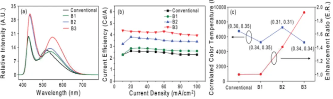
Fig. 4. (a) Blue-conversion-white spectra of a conventional and three types of pc-WOLED corresponding to a 3.8 mg/cm2 sedimented phosphor layer at the normal direction. (b) Luminous efficacy-current density characteristics of the pc-WOLEDs at the normal direction. (c) The enhancement ratios of the luminous efficacy (conventional: 2.28 cd/A, B1: 2,29 cd/A, B2: 3.21 cd/A, B3: 4.38 cd/A) and the CIE 1931 coordinates and CCT at 10 mA/cm2.
Figure 4(a) shows the blue-conversion-white spectra of a conventional (Blue OLED + YAG:Ce) and three different types (B1:Blue OLED + LRF + YAG:Ce, B2:Microcavity blue OLED + YAG:Ce, B3:Microcavity blue OLED + LRF + YAG:Ce) of pc-WOLEDs at the normal direction. Figure 4(b) shows the luminous efficacy-current density characteristics of the fabricated pc-WOLEDs measured from the direction normal to the substrate. The current efficiency of the conventional, B1, B2, and B3 pc-WOLEDs correspond to 2.28 cd/A, 2.29 cd/A, 3.21 cd/A, and 4.38 cd/A at 10 mA/cm2, respectively. The enhancement ratios of the
effect of blue transmission of the conventional OLED reflected by the LRF cancels the increased effect of forward emission recycled by the yellow reflection of LRF. The pc-WOLED combined with a moderate microcavity, i.e., B2, improves the luminous efficacy. This is due to the enhanced intensity and the narrowed spectrum of blue emission from the microcavity OLED source. Finally, a large enhancement of luminous efficacy and intensity of the white emission spectrum is observed from the pc-WOLED combined with both a microcavity structure and LRF layers. The higher transmission of the LRF stacks at the blue wavelength of the microcavity OLED excites the over-coated yellow phosphor layer on the LRF-assisted substrate, showing that is larger than that of a phosphor on a conventional OLED. In addition, the high reflectance band of the LRF stacks at the yellow wavelength can recycle a large amount of the backward yellow phosphor emission that would otherwise be absorbed by the OLED device. In the case of B3, the blue emission of the blue OLED is enhanced owing to the microcavity effect, and the yellow emission of the YAG:Ce phosphor is enhanced thanks to the LRF. Therefore, B3 enhances the entire white emission range, resulting in the greatest enhancement of efficiency.
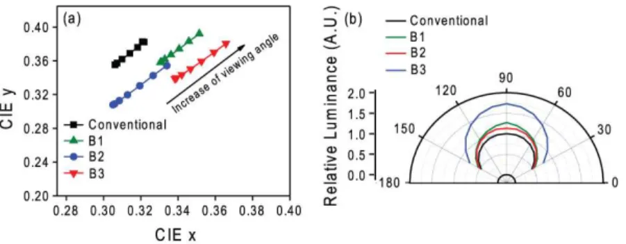
Fig. 5. Angular dependencies of (a) CIE 1931 color coordinates and (b) radiation patterns.
For satisfaction of the lighting requirement, the chromaticity should be taken into account. The Commission International d’Eclairage (CIE) 1931 coordinates of B3 pc-WOLED are (0.34, 0.34) and the correlated color temperature (CCT) is 4800 K [see Fig. 4(c)]. We also emphasize that the proposed pc-WOLEDs show comparable variations in their CIE color coordinates [see Fig. 5(a)] and their angular radiation patterns [see Fig. 5(b)] over a large angular span to those of a conventional pc-WOLED.
3. Conclusions
In summary, we proposed and demonstrated a highly efficient pc-WOLED combining both a moderate microcavity structure and LRFs. The luminous efficacy of the moderate microcavity pc-WOLED incorporating yellowish LRF was enhanced by 1.92 times with CIE 1931 coordinates (0.34, 0.34) and a CCT of 4800 K. Furthermore, our pc-WOLED provides an acceptable viewing-angular tolerance.
Acknowledgements
This study was supported by Korea Science and Engineering Foundation (Nano R&D program grant # 2008-03573 and ERC program grant # R11-2005-048-00000-0) and a grant (code# F0004100-2008-31) from the Information Display R&D Center, one of the 21st Century Frontier R&D Programs funded by the Ministry of Knowledge Economy of Korea. This work was partially supported by the National Research Foundation of Korea Grant funded by the Korean Government (MEST) (NRF-C1AAA001-2009-0092938). S.-H. Cho and J. R. Oh contributed equally to this work.