Electric Power System Architecture for the Proton Accelerator Conventional Facilities
Kyeong-Jun Mun,a Gye Po Jeon,a Jun Yeon Kim,a Byung Ho Choi,a Won Hee Lee,b Woo Sung Jung,b Suk Tae Yoo ba Korea Atomic Energy Research Institute, Proton Engineering Frontier Project P.O. Box 105, Yuseong, Daejeon, 305-353, Korea, [email protected]
b Korea Power Engineering Company, INC.
360-9 Mabuk-ri, Guseong-eup, Yongin-si, Gyeonggi-do, [email protected]
1. Introduction
The Proton Engineering Frontier Project (PEFP), approved and launched by the Korean government in July 2002, consist of a 100 MeV proton linear accelerator development and programs for its utilization and application. According to PEFP, expected to complete in March 2012, proton accelerator research center will be founded on the project host site where Korean government will select.
In this paper, electric power system architecture for the proton accelerator conventional facilities in PEFP is described. To supply electric power to the proton accelerator conventional facilities in PEFP, we adopted 154kV substation facilities with 2 transformers. For the emergency power system, we adopted emergency diesel generator, battery and UPS.
To show the usefulness of the proposed electric power system, we compare them to that of SNS now constructing in USA and ESS in Europe[1,2].
2. Designed Electric Power System for the Proton Accelerator Conventional Facilities
To show the usefulness of the proposed electric power system for the proton accelerator conventional facilities, it is compared to that of SNS[1] and ESS[2]. 2.1 Electric Power System for the Proton Accelerator Conventional Facilities
In this paper, we designed 154kV substation facility system which receives power through a 154kV overhead transmission line from the 154kV substation of KEPCO. It supplies electric power to the proton accelerator facilities via 154/3.3kV step-down transformers with 3 phase, delta-wye connection. The components of the 154kV substation are : outdoor type, 170kV totally enclosed gas insulated switchgear(GIS), gas insulated buses(GIB), power circuit breakers, disconnecting switches current transformers, voltage transformers, earthing switches, surge arresters, etc.
As shown in Figure 1, The 3.3kV switchgear system consists of power supply system of RF (A system) with the capacity of 20/26.6MVA, and conventional facilities (B system) with the capacity of 10/13.3MVA. Each system can receive power from 2 transformers during normal operation. If the operating transformer fails, the faulted source should be isolated by relay and breaker operation. After fault isolation, corresponding
system receives power from the other transformer via related switchgear operation.
We adopted double busbar arrangement because if a fault occurs in a busbar, loads of the corresponding busbar are transferred to the other busbar by operating disconnecting switches.
In contrast, as shown in Figure 1 (b), SNS adopt ring busbar arrangement with 13.8kVac, nominal, 3-phase 3-wire. By adopting ring busbar, reliability is enhanced because it is easy to transfer load of the faulted bus section. But there are some possibilities of maloperation because of its complex structure.
(a) proposed 154/3.3kV substation facility system
(b) substation facility system of SNS Figure 1 Substation Facility System Transactions of the Korean Nuclear Society Autumn Meeting
2.2 Emergency Power System
If electric power from the transformer is lost due to any reason, emergency generator set supplies power to the critical loads, DC power system with battery chargers and UPS(Uninterruptible Power Supply) system are also operated to minimize the economical loss and guarantee the safety of the operators.
The continuous rating of emergency diesel generator is designed to measure in kilowatts at 0.8 power factor. The emergency diesel generator unit can operate for 2000 hours continuously without excessive vibration or engine/generator damage. In this paper, we installed diesel generator to the proton accelerator, Beam application building, main office and dormitory building.
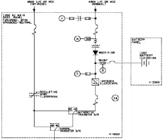
DC power system has a nominal voltage rating of 125V. It consists of battery, battery charger and DC control center. AC power supplied from 480V emergency diesel generator bus is transformed to DC power through the battery charger in order to supply DC power to the DC loads of conventional facilities for proton acceleration and the 120V UPS system.
Vital AC instrument power system use UPS to provide reliable AC electric power with constant voltage and frequency to the vital control and instrument devices which require uninterrupted power in conventional facilities for Proton Accelerator Conventional Facilities such as voltage fluctuation, momentary interruption of power supply, frequency fluctuation and blackout. General UPS configuration is shown in Figure 2.
Figure 2 UPS configuration
In Figure 3, we described emergency power system proposed in this paper, which consists of emergency diesel generator, battery charger system, and UPS.
3. Conclusion
In this paper, we designed the electric power system for the proton accelerator conventional facilities. Designed electric power system is composed of 154kV substation facilities with 2 transformers to supply electric power to the proton accelerator conventional facilities, emergency power system.
(a) Battery Charger and UPS system
(b) Emergency Power System Configuration
Figure 3 Battery Charger, UPS system and Emergency Power System Configuration in the Proton Accelerator
Conventional Facilities
To show the usefulness of the proposed electric power system, we compare them to that of SNS now constructing in USA and ESS in Europe[1,2].
ACKNOWLEDGEMENT
This work is a part of the “Proton Engineering Frontier Project” which is sponsored by the Ministry of Science and Technology of Korea under “21C Frontier R&D Program”.
REFERENCES
[1] Report of the Spallation Neutron Source, 1997
[2] European Spallation Source:Volume 3, The ESS Technical Study, Report ESS 96-53-M, Nov., 1996