Journal of International Conference on Electrical Machines and Systems Vol. 3, No. 4, pp. 446~450, 2014 446
Optimal Design of Electromagnetic Actuator with Divided Coil
Excitation to Increase Clamping Force
Tae-Woo Kim *, and Jung-Hwan Chang
*Abstract – This paper performed the optimal design of electromagnetic linear actuator with
divided coil excitation. The table of orthogonal array and response surface methodology (RSM) are applied to maximize the clamping force of the electromagnetic linear actuator with colenoid (COL) and multipolar solenoid (MPS) excitation. The analysis results show that the clamping force of the optimal models with COL and MPS excitation are increased by 41% and 54% at the gap of 0mm compared to the initial models, respectively.
Keywords:
Electromagnetic linear actuator, Colenoid, Solenoid, Clamping force, Optimal design1. Introduction
In the linear motion application, the conventional linear actuators have been widely used by applying hydraulic and pneumatic cylinders. In the hydraulic system, it is possible to obtain large force over long stroke. However, the hydraulic equipment can be expensive due to the hydraulic power pack for supplying hydraulic fluid and the separate control unit for regulating it. Also, hydraulic devices have the problems such as low energy efficiency, complexity of the system, oil leaks, and difficulty of maintenance.
In order to solve these problems, the hydraulic systems can be replaced by electromagnetic linear actuator. It has been developed in many applications, such as hydraulic/fuel control valves, chucking system, clamping device, and so on [1]. However, electromagnetic linear actuators still have lower force density compared to the hydraulic system and have been applied to comparatively short stroke applications. The electromagnetic linear actuators with a divided coil excitation system such as colenoid (COL) and multipolar solenoid (MPS) are proposed in [2]. The COL excitation is advantageous for a short stroke operation and the MPS excitation is useful for a middle stroke region.
In this paper, the optimal design of electromagnetic linear actuator with the divided coil excitation is performed using the table of orthogonal array and response surface methodology (RSM) to increase the clamping force at the gap of 0mm. The axisymmetric finite element analysis
(FEA) is performed for the COL and MPS excitation. The optimal values of the design parameters are determined, and the results are compared with the clamping force of two initial models. One has equivalent width of stator poles and the other has equivalent cross-sectional area of stator poles. The analysis results show that the clamping force of the optimal models with COL and MPS excitation are increased by 41% and 54% at the gap of 0mm compared to the initial models, respectively.
2. Initial Models and Analysis
Fig. 1 shows a cross-sectional view of axisymmetric model of the electromagnetic linear actuator with divided coil excitation. It consists of a clamping plate, stator core and numbered coils from inside to outside. In the case of colenoid (COL) excitation, the magnetomotive force (MMF) of the each coil has alternating polarity in adjacent positions. When the MMFs of the coils have the same directions, it is called multipolar solenoid (MPS). The applied MMF to the analysis model is 1500 AT across the divided coils. The electromagnetic characteristics including magnetic force are obtained by the axisymmetric finite element analysis (FEA). At first step, two initial models are analyzed. One has the stator poles with equivalent width and the other has equivalent cross-sectional area of stator poles as shown in Fig. 2 (a) and Fig. 2 (b), respectively.
Table 1 shows the analysis results of the clamping force with COL and MPS excitation at the gap of 0mm. The clamping force of COL excitation is bigger than that of MPS excitation. Also, when the stator poles have same cross-sectional area, they produce smaller clamping force
* Dept. of Electrical Engineering, Dong-A University, Korea. ([email protected])
447 Optimal Design of Electromagnetic Actuator with Divided Coil Excitation to Increase Clamping Force compared with the model having equivalent stator pole
width. Fig. 3 shows the magnetic flux density at air-gap of 0.1mm between the clamping plate and the stator core. Each pole has different magnitude of flux density. To increase the clamping force, the magnitude and distribution of magnetic flux density need to be uniform.
Fig. 1. Cross-sectional view of electromagnetic linear
motor
(a)
(b)
Fig. 2. Initial models of electromagnetic linear motor (a)
stator poles with equivalent width (b) stator poles with equivalent cross-sectional area
Table 1. Clamping force of initial models
Initial Models Equivalent width Equivalent cross-sectional area Excitation
Method COL MPS COL MPS
Clamping Force @ 0mm (kN) 31.23 26.92 28.51 25.34 40 50 60 70 80 90 100 110 120 130 -3 -2 -1 0 1 2 3
Equi-width Model (COL) Equi-area Model (COL)
A ir g a p F lu x D e n si ty ( T ) Position (mm) (a) 40 50 60 70 80 90 100 110 120 130 -3 -2 -1 0 1 2 3 Equi-width Model (MPS) Equi-area Model (MPS) A ir g a p F lu x D e n si ty ( T ) Position (mm) (b)
Fig. 3. Air-gap flux density distribution for initial models
(a) COL excitation (b) MPS excitation
3. Optimal Design
To maximize the clamping force, at first, the most influencing design variables and their levels are determined and arranged in the table of orthogonal array. The table of orthogonal array considers many parameters without expansion of experiment and it excludes information about an interaction of higher degree between variables [3]. The clamping forces on each experiment are calculated by a commercial software, FLUX 2D, and main effect analysis are used to get the influence of each design variable on the object function. Base on this result, rescaled range of each design variable is applied to the response surface
methodology (RSM) to optimize the electromagnetic linear actuator with COL and MPS excitation.
The object function is to maximize the clamping force
FCC and FCM for COL and MPS excitation, respectively.
The fixed dimensions are inside and outside diameters and width of each slot area as shown in Fig. 1. One dimension of the stator pole width can be determined by the fixed dimensions and the other dimensions of the stator poles. So, five design variables, x1, x2, x3, x4, and h, of the electromagnetic linear actuator with COL and MPS excitation are set as shown in Fig. 4. These design variables are closely related to the clamping force. Each design variable is classified into three levels. Table 2 shows the design variables and their levels.
Based on the FEA simulation result, the main effect analysis is carried out to estimate the effects of design variables and determine the relative importance of each design variable. The main effect is calculated by the mean of the object function value corresponding to level of each design variable and deviation of it.
(a) (b)
Fig. 4. Design variables of electromagnetic linear actuator
(a) COL excitation (b) MPS excitation
Table 2. Design variables and levels of table of orthogonal
array for COL and MPS excitation Level Design Variable -1 0 +1 Width of Poles (mm) x1 1 9 17 x2 1 9 17 x3 1 9 17 x4 1 9 17
Stator Back-yoke and Height of Clamping
Plate (mm)
h 5 12.5 20
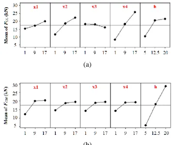
The main effects of each parameter for COL and MPS excitation are shown in Fig. 5. The effect of each design variable and contribution on the clamping force should be considered by Fig. 5. The most influencing design variables of clamping force by COL excitation are x4, x2, and h as shown in Fig. 5 (a). This is due to the magnetic flux concentration in even number of stator poles. In the case of
MPS excitation, the design variable h is the most influencing to the clamping force as shown in Fig. 5 (b). Unlike the COL excitation, the magnetic flux generated by MPS excitation flows through the clamping plate and stator back-yoke in one direction.
(a)
(b)
Fig. 5. Main effect for means of clamping force (a) COL
excitation (b) MPS excitation
Table 3 and Table 4 show the design variables and their levels of CCD for COL and MPS excitation, respectively. The two fitted second-order polynomial of object function for five design variables given as (1) and (2).
h x h x x x h x x x x x h x x x x x x x h x x x x h x x x x FCC 4 0881 . 0 3 1831 . 0 4 3 7269 . 0 2 0669 . 0 4 2 2856 . 4 3 2 6219 . 0 1 1769 . 0 4 1 5606 . 1 3 1 6319 . 0 2 1 1256 . 1 0298 . 0 4 6252 . 2 3 1802 . 0 2 1915 . 2 1 704 . 0 5713 . 0 4 5363 . 0 3 2821 . 0 2 7954 . 0 1 8421 . 0 9939 . 41 2 2 2 2 2 (1) h x h x x x h x x x x x h x x x x x x x h x x x x h x x x x FCM 4 0.4413 3 4463 . 0 4 3 8575 . 0 2 355 . 0 4 2 7663 . 0 3 2 7638 . 0 1 445 . 0 4 1 7712 . 0 3 1 7538 . 0 2 1 7525 . 0 01375 . 0 4 1288 . 0 3 0688 . 0 2 125 . 0 1 0875 . 0 65 . 5 4 4117 . 1 3 24 . 1 2 005 . 1 1 145 . 1 9.1633 2 2 2 2 2 2 (2)
It is necessary to examine the fitted second-order polynomial of object function to ensure that it provides an adequate approximation to the true response. In order to confirm adequacy of the fitted second-order polynomial of object function, the adjusted coefficient of determination
adj
449 Optimal Design of Electromagnetic Actuator with Divided Coil Excitation to Increase Clamping Force estimated error variance provided by the residual mean
square of the error variance estimation using the total mean square [5]. The adjusted coefficient of determination
adj
R2 for clamping force for COL and MPS excitation are 98.6% and 98.3%, respectively. This means that the second-order polynomials have a good accuracy for this range of design variables.
Table 3. Design variables and levels of CCD for COL
excitation Level Design Variable -α -1 0 +1 + α Width of Poles (mm) x1 9 11 13 15 17 x2 9 11 13 15 17 x3 1 3 5 7 9 x4 10 12 14 16 18 Stator Back-yoke and
Height of Clamping Plate (mm)
h 12 14.5 17 19.5 22
Table 4. Design variables and levels of CCD for MPS
excitation Level Design Variable -α -1 0 +1 + α Width of Poles (mm) x1 9 11 13 15 17 x2 9 11 13 15 17 x3 1 3 5 7 9 x4 1 3 5 7 9 Stator Back-yoke and Height
of Clamping Plate (mm)
h 12 14.5 17 19.5 22
Fig. 6 shows response surface for design variables of clamping force (FCC and FCM). These plots present the
clamping force according to the variation of selected two variables.
Table 5 shows the optimal value of design variables and clamping force between COL and MPS excitation. It shows that the clamping force of the optimal models with COL and MPS excitation are increased by 41% and 54% at the gap of 0mm compared to the initial model having equivalent width of stator poles, respectively. Comparing the magnetic flux density distribution between initial and optimized models, uniformity of the magnetic flux density distribution has dominant influence on the clamping force as shown in Fig. 7.
Fig. 8 compares clamping forces between initial model having equivalent pole width and optimized model with the variation of airgap length. With the optimized value at the
gap of 0mm, the optimum model has bigger clamping force than the initial model at the entire displacement.
(a)
(b)
Fig. 6. Response surface for design variables (a) FCC (x4, h)
for COL (b) FCM (x4, h) for MPS
Table 5. Optimal values and clamping force of initial and
optimal model
Design Variable Optimal Model
COL MPS x1 (mm) 9 15 x2 (mm) 9 13 x3 (mm) 9 5 x4 (mm) 18 3 h (mm) 22 22 Clamping Force @ 0mm (kN) 44.04 41.38
4. Conclusion
This paper performed optimal design of electromagnetic linear actuator with the divided coil excitation such as COL and MPS. The most effective design variables are extracted by main effect analysis through the table of orthogonal array. The influence of each design variable on the object function can be obtained. The optimization values of design parameters are determined by RSM. The analysis results show that the clamping force of the optimal models with COL and MPS excitation are increased by 41.02% and 32.5% at the gap of 0mm compared to the initial model having equivalent pole width, respectively.
40 50 60 70 80 90 100 110 120 130 -3 -2 -1 0 1 2 3
Initial Model with Equi-width (COL) Optimal Model (COL)
A ir g a p F lu x D e n si ty ( T ) Position (mm) (a) 40 50 60 70 80 90 100 110 120 130 -3 -2 -1 0 1 2 3
Initial Model with Equi-width(MPS) Optimal Model (MPS) A ir g a p F lu x D e n si ty ( T ) Position (mm) (b)
Fig. 7. Air-gap flux density distribution (a) COL excitation
(b) MPS excitation 0 1 2 3 4 5 0 10 20 30 40 50 C la m p in g F o rc e (k N ) Displacement (mm)
Initial Model with Equi-width (COL) Optimal Model (COL)
(a) 0 1 2 3 4 5 0 10 20 30 40
50 Initial Model with Equi-width (MPS)
Optimal Model (MPS) C la m p in g F o rc e ( k N ) Displacement (mm) (b)
Fig. 8. Clamping force versus displacement (a) COL (b)
MPS
References
[1] J. H. Kim and J. H. Chang, “A new electromagnetic linear actuator for quick latching,” IEEE Trans.
Magnetics, vol. 43, no. 4, pp. 1849-1852, Apr. 2007.
[2] H. Mutai and K. Yamasawa, “Fundamental operation of a multipolar disk-solenoid,” IEEE Trans. Magnetics, vol. 31, no. 4, pp. 2445-2449, Jul. 1995.
[3] S. G. Seo and N. S. Kim, “Optimum design of the cored linear motor using experiment design,” Journal
of Mechanical Science and Technology, vol. 23, no. 8,
pp. 2215-2223, Aug. 2009.
[4] Y. K. Kim, J. P. Hong, G. H. Lee, and Y. S. Jo, “Application of response surface methodology to robust design for high temperature superconducting magnet,” IEEE Trans. Applied Superconductivity, vol. 12, no. 1, pp. 1434-1437, Mar. 2002.
[5] Y. C. Choi, H. S. Kim, and J. H. Lee, “Optimum design criteria for maximum torque density and minimum torque ripple of SynRM according to the rated wattage using response surface methodology,” IEEE Trans.
Magnetics, vol. 44, no. 11, pp. 4135-4138, Nov. 2008.
Tae-Woo Kim received B.S. and M.S.
degrees in electrical engineering from Dong-A University, Busan, Rep. of Korea in 2011 and 2013, respectively. He is currently working toward the Ph.D. degree at the same University. His research interests are the analysis and design of permanent magnet synchronous motor.
Jung-hwan Changreceived B.S. and M.S. degrees in electrical engineering and Ph.D. degree in precision mechanical engineering from Hanyang University, Seoul, Rep. of Korea in 1994, 1997 and 2001, respectively. From 2001 to 2002, he worked at Institute of Brain Korea 21 at Hanyang University, where he developed micro drive and high-speed spindle motor. From 2002 to 2003, he worked as research fellow at University of California at Berkeley with the support of Korea Science and Engineering Foundation, and analyzed and developed electrically controlled engine valve system. From 2003 to 2009, he worked in Korea Electro technology Research Institute (KERI) as a senior researcher, and engaged in the developments of special purpose machines. Since 2009, he has been with the department of electrical engineering, Dong-A University, Busan Rep. of Korea, as an associate professor. His interests are the design, analysis and control of electro-mechanical systems.