See-through display combined with
holographic display and Maxwellian display
using switchable holographic optical element
based on liquid lens
J
INS
UL
EE, Y
OOK
WANGK
IM,
ANDY
ONGH
YUBW
ON*School of Electrical Engineering, Korea Advanced Institute of Science and Technology, Daejeon 34141, South Korea
Abstract: We report a switchable holographic optical element based on a liquid lens for a
see-through display. For the switchable holographic optical element, we recorded two optical components in the holographic film in two steps. A numerical simulation was also done to define the recording and reconstruction conditions. After the recording process, the entire system was changed from 4f optics to Maxwellian optics by changing wavefront of the reference wave using a liquid lens. The diffraction efficiency was 0.46 for a single element recording and around 0.14 for a double element recording. The holographic display and the Maxwellian display were successfully switched without any crosstalk. The field of view and eye box of the holographic display were 1° and 4.36 mm, respectively, and the field of view and the eye box of the Maxwellian display were 3.8° and 23.2 um, respectively. In the proposed system, spatial frequency filtering by the liquid lens and image shape distortion seriously affected the hologram image. However, we successfully verified the feasibility of our proposed switchable holographic optical element using a liquid lens.
© 2018 Optical Society of America under the terms of the OSA Open Access Publishing Agreement
OCIS codes: (090.2870) Holographic display; (090.2820) Heads-up displays; (090.2645) Stratified volume
holograms; (080.3620) Lens system design.
References and links
1. Q. Gao, J. Liu, J. Han, and X. Li, “Monocular 3D see-through head-mounted display via complex amplitude modulation,” Opt. Express 24(15), 17372–17383 (2016).
2. S. Reichelt, R. Häussler, G. Fütterer, and N. Leister, “Depth cues in human visual perception and their realization in 3D display,” Proc. SPIE 7690(1), 76900B (2010).
3. J. L. Martinez, E. J. Fernandez, P. M. Prieto, and P. Artal, “Chromatic aberration control with liquid crystal spatial phase modulators,” Opt. Express 25(9), 9793–9801 (2017).
4. Q. Gao, J. Liu, X. Duan, T. Zhao, X. Li, and P. Liu, “Compact see-through 3D head-mounted display based on wavefront modulation with holographic grating filter,” Opt. Express 25(7), 8412–8424 (2017).
5. S. A. Goorden, J. Bertolotti, and A. P. Mosk, “Superpixel-based spatial amplitude and phase modulation using a digital micromirror device,” Opt. Express 22(15), 17999–18009 (2014).
6. Z. Zeng, H. Zheng, Y. Yu, A. K. Asundi, and S. Valyukh, “Full-color holographic display with increased-viewing-angle [Invited],” Appl. Opt. 56(13), F112–F120 (2017).
7. Y. Z. Liu, X. N. Pang, S. Jiang, and J. W. Dong, “Viewing-angle enlargement in holographic augmented reality using time division and spatial tiling,” Opt. Express 21(10), 12068–12076 (2013).
8. Y. Takaki and M. Yokouchi, “Speckle-free and grayscale hologram reconstruction using time-multiplexing technique,” Opt. Express 19(8), 7567–7579 (2011).
9. Y. Mori, T. Fukuoka, and T. Nomura, “Speckle reduction in holographic projection by random pixel separation with time multiplexing,” Appl. Opt. 53(35), 8182–8188 (2014).
10. L. Golan and S. Shoham, “Speckle elimination using shift-averaging in high-rate holographic projection,” Opt. Express 17(3), 1330–1339 (2009).
11. A. Jesacher, S. Bernet, and M. Ritsch-Marte, “Broadband suppression of the zero diffraction order of an SLM using its extended phase modulation range,” Opt. Express 22(14), 17590–17599 (2014).
12. J. Liang, S. Y. Wu, F. K. Fatemi, and M. F. Becker, “Suppression of the zero-order diffracted beam from a pixelated spatial light modulator by phase compression,” Appl. Opt. 51(16), 3294–3304 (2012).
13. M. Kick, R. Fie, and W. Stork, “Sequential and non-sequential simulation of volume holographic gratings,” J. Eur. Opt. Soc.-Rapid Pub. 14(1), 15 (2018).
#330790 https://doi.org/10.1364/OE.26.019341
14. N. Kim, Y. L. Piao, and H. Y. Wu, “Holographic Optical Elements and Application.” In Holographic Materials and Optical Systems. InTech, (2017).
15. J. S. Lee, Y. K. Kim, and Y. H. Won, “Time multiplexing technique of holographic view and Maxwellian view using a liquid lens in the optical see-through head mounted display,” Opt. Express 26(2), 2149–2159 (2018). 16. G. Kramida, “Resolving the Vergence-Accommodation Conflict in Head-Mounted Displays,” IEEE Trans. Vis.
Comput. Graph. 22(7), 1912–1931 (2016).
17. M. Waldkirch, P. Lukowicz, and G. Tröster, “Oscillating fluid lens in coherent retinal projection displays for extending depth of focus,” Opt. Commun. 253(4–6), 407–418 (2005).
18. H. Urey, S. Holmstrom, U. Baran, K. Aksit, M. K. Hedili, and O. Eides, “MEMS scanners and emerging 3D and interactive Augmented Reality display applications,” in 2013 Transducers & Eurosensors XXVII: The 17th
International Conference on Solid-State Sensors, Actuators and Microsystems (TRANSDUCERS & EUROSENSORS XXVII), 2485–2488 (2013).
19. D. W. Kim, Y. M. Kwon, Q. H. Park, and S. K. Kim, “Analysis of a head-mounted display-type multifocus display system using a laser scanning method,” Opt. Eng. 50(3), 034006 (2011).
20. W. Jia, Z. Chen, F. J. Wen, C. Zhou, Y. T. Chow, and P. S. Chung, “Coaxial holographic encoding based on pure phase modulation,” Appl. Opt. 50(34), H10–H15 (2011).
21. H. Kogelnik, “Coupled wave theory for thick hologram gratings,” Bell Syst. Tech. J. 48(9), 2909–2947 (1969). 22. H. J. Yeom, H. J. Kim, S. B. Kim, H. Zhang, B. Li, Y. M. Ji, S. H. Kim, and J. H. Park, “3D holographic head
mounted display using holographic optical elements with astigmatism aberration compensation,” Opt. Express
23(25), 32025–32034 (2015).
23. J. Marín-Sáez, J. Atencia, D. Chemisana, and M. V. Collados, “Characterization of volume holographic optical elements recorded in Bayfol HX photopolymer for solar photovoltaic applications,” Opt. Express 24(6), A720– A730 (2016).
24. A. Zanutta, E. Orselli, T. Fäcke, and A. Bianco, “Photopolymeric films with highly tunable refractive index modulation for high precision diffractive optics,” Opt. Mater. Express 6(1), 252–263 (2016).
25. G. Li, D. Lee, Y. Jeong, J. Cho, and B. Lee, “Holographic display for see-through augmented reality using mirror-lens holographic optical element,” Opt. Lett. 41(11), 2486–2489 (2016).
26. A. Sure, T. Dillon, J. Murakowski, C. Lin, D. Pustai, and D. Prather, “Fabrication and characterization of three-dimensional silicon tapers,” Opt. Express 11(26), 3555–3561 (2003).
27. S. Blaya, L. Carretero, R. Mallavia, A. Fimia, R. F. Madrigal, M. Ulibarrena, and D. Levy, “Optimization of an acrylamide-based dry film used for holographic recording,” Appl. Opt. 37(32), 7604–7610 (1998).
28. O. Prucker, M. Schimmel, G. Tovar, W. Knoll, and J. Rühe, “Microstructuring of Molecularly Thin Polymer Layers by Photolithography,” Adv. Mater. 10(14), 1073–1077 (1998).
29. H. Wei, G. Gong, and N. Li, “Improved look-up table method of computer-generated holograms,” Appl. Opt.
55(32), 9255–9264 (2016).
30. K. Matsushima and S. Nakahara, “Extremely high-definition full-parallax computer-generated hologram created by the polygon-based method,” Appl. Opt. 48(34), H54–H63 (2009).
31. Y. Zhao, L. Cao, H. Zhang, D. Kong, and G. Jin, “Accurate calculation of computer-generated holograms using angular-spectrum layer-oriented method,” Opt. Express 23(20), 25440–25449 (2015).
32. H. Zhang, L. Cao, and G. Jin, “Computer-generated hologram with occlusion effect using layer-based processing,” Appl. Opt. 56(13), F138–F143 (2017).
33. K. Matsushima and T. Shimobaba, “Band-Limited Angular Spectrum Method for Numerical Simulation of Free-Space Propagation in Far and Near Fields,” Opt. Express 17(22), 19662–19673 (2009).
34. P. Sun, S. Chang, S. Liu, X. Tao, C. Wang, and Z. Zheng, “Holographic near-eye display system based on double-convergence light Gerchberg-Saxton algorithm,” Opt. Express 26(8), 10140–10151 (2018). 35. H. E. Hwang, H. T. Chang, and W. N. Lie, “Fast double-phase retrieval in Fresnel domain using modified
Gerchberg-Saxton algorithm for lensless optical security systems,” Opt. Express 17(16), 13700–13710 (2009). 36. S. Vorndran, J. M. Russo, Y. Wu, S. A. Pelaez, and R. K. Kostuk, “Broadband Gerchberg-Saxton algorithm for
freeform diffractive spectral filter design,” Opt. Express 23(24), A1512–A1527 (2015).
37. A. Maimone, A. Georgiou, and J. S. Kollin, “Holographic near-eye displays for virtual and augmented reality,” ACM Trans. Graph. 36(4), 85 (2017).
38. N. Hasan, H. Kim, and C. H. Mastrangelo, “Large aperture tunable-focus liquid lens using shape memory alloy spring,” Opt. Express 24(12), 13334–13342 (2016).
39. R. Häussler, S. Reichelt, N. Leister, E. Zschau, R. Missbach, and A. Schwerdtner, “Large real-time holographic displays: from prototypes to a consumer product,” Proc. SPIE 7237, 72370S (2009).
40. R. Häussler, Y. Gritsai, E. Zschau, R. Missbach, H. Sahm, M. Stock, and H. Stolle, “Large real-time holographic 3D displays: enabling components and results,” Appl. Opt. 56(13), F45–F52 (2017).
41. S. B. Kim and J. H. Park, “Optical see-through Maxwellian near-to-eye display with an enlarged eyebox,” Opt. Lett. 43(4), 767–770 (2018).
42. C. Jang, K. Bang, S. Moon, J. Kim, S. Lee, and B. Lee, “Retinal 3D: augmented reality near-eye display via pupil-tracked light field projection on retina,” ACM Trans. Graph. 36(6), 190 (2017).
1. Introduction
Digital holographic display is an effective and a useful technology in various fields [1]. The digital holographic display can provide a nature scene-like object in the air by controlling the phase and amplitude of the light. Hence, the digital holographic display is considered a promising technology for next generation displays [2]. Basically, the amplitude and phase of the light are modulated by a spatial light modulator, such as a transmissive liquid crystal [1], a liquid crystal on silicon (LCOS) [3,4], or a digital mirror device (DMD) [5], etc. Although the digital holographic display has progressed tremendously by advanced semiconductor technology, it still has inevitable obstacles for commercialization, such as a small field of view (FOV), a small exit pupil, DC noise and high order noise, etc, because of the large spatial bandwidth of the spatial light modulator (SLM) [6–12]. Although most of these issues can be solved by decreasing the pixel pitch, unfortunately, current available spatial light modulators are not enough to provide a large hologram for multiple observers. Thus, current holographic display is specified for single user. Thus, most holographic displays use 4f optics with a spatial filter to eliminate DC noise and high-order noise and to compensate for chromatic aberration. However, although 4f optics is a direct solution to create a clear hologram, the 4f optics needs two solid lenses, which makes the device too heavy to use for see-through displays like head-mounted displays and glasses.
A volume holographic grating is utilized as optical elements like lenses or mirrors. They are space-saving, lightweight, wavelength and angle selectivity, transparent and potentially low-cost [13]. Additionally the volume holographic grating does have the advantage of adding freedom to the optical design process, as incidence and exit angle can be chosen independently. In addition, multiplexed volume holographic grating (or multiplexed HOE) reconstructs all multiple wave simultaneously, when reference wave enter into the multiplexed volume holographic grating [14]. In this paper, we found that the changing wavefront of reference wave by liquid lens can select the each recorded holographic optical elements. Thus, entire optical system can be changed by combination the liquid lens and the holographic film. Not only does this increase the freedom of the optical system, it is expected to be effective in terms of weight and cost. Therefore, we mainly focused on demonstrating the feasibility of the switchable holographic optical element.
In our previous research, we put together both a holographic display and a Maxwellian display using a liquid lens [15]. The Maxwellian display, which offers images that are always focused to the retina, provides extended information for the observer [16–18]. In addition, the Maxwellian display increases the availability of see-through displays for people with vision problems such as presbyopia and myopia [19].
In this paper, we described our design of a switchable holographic optical element based on a liquid lens for see-through display. The switchable holographic optical element recording setup and reconstruction setup are described in section 2. Then the optical characteristics of the switchable holographic optical element are given in section 3. Finally, concluding remarks are in section 4.
2. Design and theory of see-through display based on switchable holographic optical elements
2.1 System specification
Our proposed switchable holographic optical element based see-through display configuration was illustrated in Fig. 1. A SLM (Holoeye, LC-2012) was used and the wavelength of the laser source was 633 nm (SIGMAKOKI, 05-LHP-121). A linear polarizer was used to set phase mostly mode for the SLM. A liquid lens (Optotunes, EL-10-30-TC) was combined with a concave lens to adjust the diopter from 0 D to 20 D. The SLM, the liquid lens, and a holographic optical element were put in the same interval with f as shown in Fig. 1. When liquid lens was set to 20D, a concave mirror of 20 D is recorded on the hologrpahic optical
element. On t plane wave. T recording, we as shown in became 4f op became the M diffraction ef Generally, hig through displ outside of the enough to rid insufficient to A DC block listed in Tabl company, hen Detailed will Fig. 1 switch Tab Spatia Number of p Pixel pitc Active ar Frame ra Waveleng Exposure en Refractive i modulation (Me 2.2 Basic the A holographi Thus, interfer shown in Fig selectivity and holographic o
the other hand, Then, a concav e chose the reco Fig. 1(b). The ptics. On the o Maxwellian dis fficiency in a gh order diffra
ay. If the pixe e pupil. Assum d out high orde
o rid out high o filter was used le 1. A refract nce it was cal discuss in sect 1. Our proposed s hable holographic ble 1. Specification al Light Modulator pixel ch 36 u rea ate gth nergy 20 ndex easured) eory of hologr ic film is a kin rence pattern b g. 2. In the ho d a diffraction optical elemen
when the liqu ve mirror of a onstructed wav erefore, when ther hand, whe splay optics. O
a monochrom action and DC el pitch is suff ming that the p er diffraction. U order diffractio d to eliminate tive index mo lculated using tion 2.2. switchable hologra optical element re ns of the spatial li r (LC – 2012) 1024 x 768 um (58% fill facto 36.9 x 27.6 mm 60 Hz Hologra 633 nm mJ/cm2 (at 633 nm 0.03 raphic optical nd of photopo etween differe olographic opti efficiency are nt [14]. Amo
uid lens was set 6.7 D was rec ve by switching the liquid lens en the liquid l Our holographic matic condition noise should b ficiently small,
upil size (exit Unfortunately, on. Thus, we on DC noise [20 dulation of ho g diffraction ef
aphic optical elem ecording setup, and
ight modulator, li Di or) Clear ap Re aphic Film (C-RT2 Fil m) Average l elements olymer, which nt waves can b ical elements, major factor t ong them, the
t at 0 D, the re corded in the h g the reference s was set at 2 ens was set at c film (Litihol n in the best be considered , the high orde pupil) is 7mm the pixel pitch nly considered 0]. All items u olographic film fficiency, thic
ment based see-thr d (b) reconstructio
iquid lens, and ho
Liquid lens (E iopter range perture (diameter) Lens type esponse time 20) lm thickness e refractive index is polymerize be recorded in an angular se to characterize e diffraction e eference wave b holographic fi e wave using li 20 D, the entir t 0 D, the entir lo, C-RT20) ha t recording c to get hologra er diffraction i m, 4.5 um pixe h of our used S d DC noise in th used in this stu m was not pro
kness and wa
rough display: (a) on setup. olographic film. EL-10-30-TC) + 8.3D ~ 10 m Plano co < 2.5 16 u 1.4 ed by incident the holograph electivity, a wa the performan efficiency is t became a lm. After iquid lens re system re system ad a 99% condition. aphic see-is located el pitch is SLM was his study. udy were ovided by avelength. ) + 20 D mm onvex ms um 9 t of light. ic film as avelength nce of the the most
important to r of the diffract coupled wave of its simplic reference wa thickness. Ho wave, depend refractive ind writing beam However, we Hence, we ha diffraction eff reference wav The diffra described as where v and When v and Thus, increasi for improving wave is the on where d and Δ holographic fi reconstruct cle tion efficiency e theory was us ity [21]. The d ave and object owever, all item d on the hologr dex modulation ms, and the ra did not addre ad to adjust the ficiency. Relat ve and object w Fig action efficienc ξ denote the ξ are equal o ing refractive i g diffraction e nly value for ch
Δn respectively film, and θR and
ear object wave y was performe
sed to simulate diffraction effi t wave, avera ms, except the raphic film cha n by adjusting atio of power ess improveme
e angle of refe tionship betwe wave was calcu
g. 2. Basic model o cy of the loss 1 η= + e coupling var or v is bigger index modulat efficiency. Hen hanging as we v λ = y denote the th d θO are respec ξ e. Thus, before ed to determine e the character iciency is asso age refractivity e angle betwee aracteristics [2
the total expos in the refere nt of the refra erence wave an
en the diffract ulated for comp
of a reflection volu sless reflection 2 2 2 2 2 1 / sin h v v ξ ξ − − riable and Bra
than ξ, the d tion or increasi nce, the angle
mentioned bef cos Rcos O i d nπ λ θ θ Δ hickness and th ctively the angl
2cos O d ξ θ Γ = e experiment, e the recording ristics of the ho ociated with th y, refractive i en the referenc 21,22]. There a sure dosage, th ence and sign active index m nd object wav tion efficiency paring with me ume hologram. n volume holo 1 2 ξ − agg mismatch diffraction effi
ing film thickn between refe fore. O he refractive in le of reference a numerical si g condition. K olographic film he wavelength, index modulat ce wave and t are ways to imp
he power dens nal beams, etc modulation in th
ve to obtain the and the angle easured results.
ographic gratin
variable, resp iciency conver ness are direct erence wave an
ndex modulati wave and obje
imulation Kogelnik’s m because , angle of tion, and the signal prove the ity of the c [23,24]. his study. e optimal e between . ng can be (1) pectively. rges to 1. solutions nd object (2) ion of the ect wave. (3)
ξ is Bragg m angular devia only consider Unfortuna company. The refractive inde The angle efficiency wa reference wav shown in Fig direction of t efficiency. Ho as shown in F Fig. 3 variat mismatch variab ation and wav
ed in this study ately, refractiv erefore, we cal ex modulation e of object wa as calculated b ve was increas g. 3. In other the holographi owever, assum Fig. 4, the angle
0 10 0.0 0.1 0.2 0.3 0.4 0.5 0.6 0.7 0.8 0.9 1.0 Di ff ra cti on E ff ic ien cy 3. Numerical simu ion. Fig. 4. Sche
ble and Γ is the elength deviat y, hence ξ wa e index modu lculated refract was 0.03. cos n λ Δ =
ave was fixed by changing th sed, the diffrac words, if the ic film, the di ming that a hum e of reference w 0 20 30 0.6 0.64 0.66 Angle ulation results of ematic of angle of e Bragg misma tion [14]. How s a constant. ulation of holo
tive index mod s( R) tan h d θ π − Φ − with 0° as sh he angle of the ction efficiency reference wav iffraction effic man head was p wave of less th 40 50 0.51 0.57 62 e of Reference W
the diffraction eff
reference wave lim
atch coefficien wever, Bragg m ographic film w dulation by Eq 1( η) − hown in Fig. 2 e reference wa y was decrease ve passed thro ciency showed placed in front han 60° was im 60 70 80 0.46 0 0.33 0.438 M Wave
ficiency with refe
mitation (author’s
nt which is rela matched condi was not provid q. (4) [14]. In th
2. Thus, the d ave. When the
ed from 0.66 t ough the perp d maximum d of the hologra mpossible. 90 0.16 Measured Simulated
erence wave angle
head). ated to the ition was ded from his study, (4) diffraction angle of to 0.16 as pendicular diffraction aphic film e
Thus, the showed 0.44 with calculate 2.3 Switchab Usually, mult reference wav object waves photopolymer needs a suffic film. If expos some area as lithography of Fig. 5 lithog In this stu time as show which was m polymerizatio for 80 second with 0.07 mW intensity of e efficiency can D I and IT de On the other patterns betw interference p Fig. 6(a). The seconds as sh angle of refer in numerical ed one. ble holograph tiplexed volum ve and multiple s with maxim r, kind of dry f cient exposure sure time and e
shown in Fig f MEMS [26].
5. (a) Lithograph graphy.
udy, two differ wn in Fig. 6. In manually cont on was 20 mJ/c ds. In this case W and 0.08 mW each waves we n be described enote intensity hands, in orde ween reference pattern between en, interferenc own in Fig. 6(b rence wave (θ calculation an hic optical elem me holographic
e object waves mum efficien film with sensi e time or an e exposure dosa . 5. Some rese hy of thick phot rent interferen ntensity of refe trolled with n cm2 as shown i , intensity of d W, respectively ere measured w as η of diffracted l r to get switch e wave and o n 20 D lens an ce pattern betw b). Total expos θR) was set at nd measured re ments based c grating is rec . Then, the refe ncy [25,41].
itive on visible exposure dosag ge are not eno earchers were topolymer and (b nce patterns we erence wave a neutral density in Table 1. Thu diffracted light y. Thus, the dif with laser pow
D D T I I I η = +
light and inten hable holograph object wave w nd mirror was ween 0 D lens sure energy of 60°. Then, th esult showed 0 on liquid lens corded interfer erence wave ca The holograp e light [13,14]. ge for polymer ough, the photo applied this p
b) simple schem
ere recorded b and object wav y filter. Expo us, a single obj t and transmitt
ffraction effici wer meter (SAN
nsity of transmi hic optical ele were recorded
recorded for 6 and 6.7 D len those two proc
he diffraction e 0.46 that was s rence pattern b an reconstructs phic film is Thus, thick ph rization of ho oresist polyme phenomena in matic of grayscale by controlling ve were 0.125 osure energy ject wave was ed light were m iency showed 0
NWA). The d
itted light, resp ment, each int
step by step 60 seconds as ns was recorde cesses was 20 m efficiency a similar between a s multiple a thick hotoresist lographic erize only grayscale e exposure mW/cm2 for fully recorded measured 0.46. The diffraction (5) pectively. terference p. Firstly, shown in ed for 20 mJ/cm2.
Although patterns will begin polyme recorded nea interference p Fig. 7(b). Af patterns woul thickness beca decreased to 0 of each object Fig. 7 (c) Re Object wa (Visualization object waves holographic o Fig. 6.
it was not capt be recorded in erization from
r the surface pattern would b fter those proc ld be get as sh ause it is like b 0.14 at 8 um fi t waves also sh
7. (a) Object wave ecorded holograph
aves change as
n 1). It showe . Recording c optical element
(a) First recording
tured with TEM n two layers in m the surface [
of the hologr be recorded ins cess, the holog hown in Fig. being separated ilm thickness in howed 0.17 and
e 1 recording illus hic film with 2 laye
s reference wa ed clearly cha condition and ts were listed in
g step and (b) seco
M or Microsco nside the holo [27,28]. Thus, raphic film as side the surfac graphic film w
7(c). In this c d into two laye n numerical ca d 0.18, respecti stration, (b) Object ers. ave changes b anged object w diffraction eff n the Table 2.
ond recording step
opy, it is expect ographic film. , first interfere s shown in F e of the hologr which was rec case, the holog ers. Actually, th alculation. How ively. t wave 2 recordin by the liquid le wave without fficiency of ou p.
ted that the int Usually, photo ence pattern w Fig. 7(a). Then raphic film as corded two int graphic film is he diffraction e wever, measure ng illustration, and ens as shown any crosstalk ur proposed sw terference opolymer would be n second shown in terference s half the efficiency ed results d in Fig. 8 between witchable
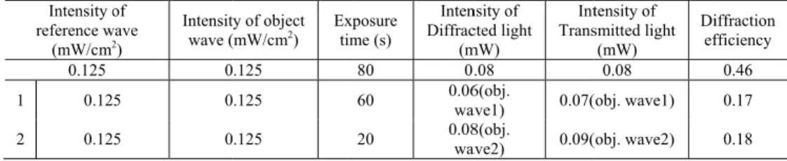
Fig. 8 (Visua Intensity o reference w (mW/cm2 0.125 1 0.12 2 0.12 Also, the a because the p the crosstalk b the experimen which was no not found ou further study. 3. Realizatio 3.1 Realizati Switchable ho as shown in F Fig. 9 Throu 8. (a) Reconstructin alization 1). Table 2. Holog of wave 2) Intensit wave ( 0 5 0 5 0 angular selectiv lane wave has between object ntal results as s ot a good resul ut yet. Thus, R on of see-thr ion of see-thr olographic opti Fig. 9(a). 9. (a) Recording ugh Display system
ng object wave 1
graphic Film reco
y of object (mW/cm2) Exptim .125 .125 .125 vity is an impo the constituen tive waves wou shown in Fig. 1 lts in numerica Relationship b rough display rough display ical elements r setup of switcha m based on switcha
(Lens) and (b) rec
ording condition a posure me (s) Inten Diffrac (m 80 0 60 0.06wa 20 0.08wa ortant value to nt parts of a sph uld be caused s 13 and 16. Alth al calculation i between crosst y based on h and image sh recording syste able holographic o able holographic o constructing objec and diffraction ef nsity of cted light mW) Int Trans .08 6(obj. ave1) 0.07( 8(obj. ave2) 0.09( avoid crosstalk herical wave. H slightly. Wher hough the angu in this study, th talk and angu holographic hape distortio em was assemb optical element f optical elements. ct wave 2 (Mirror) fficiency. tensity of smitted light (mW) Di ef 0.08 (obj. wave1) (obj. wave2) k between obje Hence, we expe reas it was not
ular selectivity heoretical reas ular selectivity optical elem on
bled on the opt
film and (b) See-) iffraction fficiency 0.46 0.17 0.18 ect waves ected that caused in y was 2.1° sons were y needs a ments tical table
-After reco as shown in reference wav to the Maxw perpendicular image shape compensated adding aspher case, the holo enlarged horiz Fig. 1 and (f 3.2 Hologram Generally, the and a depth la used a depth-can be implem holograms [3 sequences. 1. 3D obj 2. Sliced optim 3. Transf iterat 4. Extrac ording process Fig. 9(b). Th ve from 20 D t wellian optics r direction of t distortion as by adding inv rical lens phase ogram was sho zontal direction
10. (a) and (d) are f) are compensated
m generation ere are ways to ayer [29–31]. E layer hologram mented easier a 31,32]. In this ject is sliced w d layers pass G
mal phase distr fer function (A
ted sliced layer t phase distribu was done as w en the focal l to 0 D. As a re as shown in the holographic shown in Fig. verse direction e to hologram orten with hori
n. e original images, d hologram images based on Ge o generate the Each algorithm m, which is wi
and quicker tha s study, the d with several laye
Gerchberg-Sax ribution. Angular spectru
rs.
ution from the
we mentioned length of the esult, the whol Fig. 6. Usual c film [14,41], . 10(b) and 10 n distortion. It pattern or defo izontal directio
(b) and (e) are sh s.
erchberg-Saxt hologram, suc ms has its merit
dely used. Bec an the point clo depth layer-ba ers. ton Iteration A um propagatio complex ampl in chapter 2.2, liquid lens wa le system was lly, the referen
, hence the rec 0(e). The disto t can be solve ormation of or on, therefore,
hape distorted holo
ton iteration a ch as a point cl ts and demerit cause the depth oud hologram a ased hologram Algorithm with on) is added in litude of sliced , mirrors were as tuned to sw changed from nce wave wa constructed wa orted hologram e with two opt riginal image a
the original im
ogram images, (c)
algorithm loud, a triangu ts. For this rese
h layer based h and the triangu m was process h zero paddin n complex amp d layers. removed witch the 4f optics s off the ave made m can be tions that are. In our mage was ) lar patch, earch, we hologram ular patch ed under ng to find plitude of
The angul paraxial appr causes calcula was set as a p reflection mo algorithm is a distribution an algorithm giv takes a lot of times in this multiplexing processing. Th In additio proposed syst filter. Thus, in with 300x300 and speckle n 12(b) and 12( Fig. 1 and (c 3D object Fig. 13(a) and
lar spectrum a roximation of ation errors in phase only mod odel or the G a common me nd it is widely ves a precise ph f time to get p study. Althoug both the holo he hologram g
Fig.
n, the liquid l tem. When the n order to avoi 0 pixels as show
noise, the holo c) [15], becaus
2. (a) Liquid lens c) Numerical recon
ts for the holog d 13(d). Each algorithm was the Fresnel d systems with dulation. Hence erchberg-Saxst ethod to find o y used in astron hase distributio proper image q gh it took 5 se ographic displa eneration diagr 11. Depth layer ba lens we used c e liquid lens pu id low pass filt wn in Fig. 12(a ogram became se high frequen
and hologram patt nstructed hologram graphic display reconstructed used as the tr diffraction, usin a high numeric e, it needs to re ton Iteration A out optimal ph nomy, biology on than the oth
quality. Howev econds for each ay and the M
ram was illustr
ased hologram gen
could not cove ut at the cente tering problem a). Although th sharper than ncy component tern, (b) Numerica m of letter ‘K’. y were used w hologram plac ransfer functio ng the Fresne cal aperture [1 etrieval phase d Algorithm (G hase distributio y, display, and her phase retrie ver, GS algori h layers, this r Maxwellian disp rated in Fig. 11 neration diagram. er the entire a er of the SLM, m, the hologram he hologram sh our previous s t were passed. al reconstructed ho
with square and ced 50 cm beh on. Because, d el diffraction a 15,33]. Also, u distribution by S algorithm) on for target a d so forth. Alth eval methods [3
ithm was done research focuse play, not the 1. area of the SL , it worked as m pattern was g howed rough r study as show ologram of square, d letter ‘K’ as hind the SLM. due to the algorithm used SLM y adding a [34]. GS amplitude hough GS 34–36], it e for 100 ed on the real time M in our low pass generated resolution wn in Fig. , shown in . And the
reconstructed see in Fig. 13 appeared. Th Although the speckles beca intended posit 3.3 Maxwelli Maxwellian extending dep eye, numerica enough to cov enters into th image as show The depth hologram was 3(b) and 13(e) he yellow lined reconstructed ause of small tion. Fig
ian display (re display (or R pth of focus (D al aperture of t ver changing o he lens of eye, wn in Fig. 15 w Fig. 14 h of focus is des s captured by a , when the cam d boxes in Fi d hologram sho number of p g. 13. Original ima etinal projecti Retinal project DoF). When sm the plane wav of eye’s diopte
the DoF beco which was simu
4. Schematic of op
scribed as
a monochrome mera was focu ig. 13 are mag owed rough im pixels, the hol
ages and reconstru
ion display) tion display) mall diameter e is extremely er as shown in omes infinity.
ulated with opt
ptical system of M e CCD camera used at 50 cm gnifications of mage resolutio logram was c ucted hologram. is a display of plane wav y large. Thus, t n Fig. 14. For Therefore, obs tical simulation Maxwellian display (Stingray). As position, the h f the captured on and large nu orrectly forme technology e e enter into th the DoF becom
instance, if la server always n tool (Zemax) y. s you can hologram d images. umber of ed at the extremely he lens of mes large aser beam see clear ).
λ, f and d de plane wave sp (d) can be det the pupil was be seen clearl Fig. 1 cm, (b ‘KAIST’ l cm and 1 m an enote waveleng preads from th termined simpl 25 mm, the D y, when eye fo 15. Simulation res b) 50 cm, (c) 70 cm
letters and bolt nd the images D gth, focal leng e SLM with di le triangular fu oF was 1.7 mm ocuses on an ob
sults of our design m and (d) 100cm.
t used as the M were not blurr
2 2 8 f DoF d λ = gth and beam iffraction angle unction and it w m ~1.8 mm. In bject from 60cm ned Maxwellian d Maxwellian im ed as you can s diameter, resp e as shown in F was 1.3 mm. A this case, the M m to infinity.
display, when eye
mages. Then, th see in Fig. 16. pectively. Actu Fig. 14. Beam Assuming that Maxwellian im focused at (a) 30 he camera focu (6) ually, the diameter length of mages can 0 used at 50
3.4 Field of v Field of view [15,37]:
where p and L object and the and 4.36 mm,
The FOV
where f and R lens has a 150 our proposed size of the liq
The FOV not sufficient +/−25 deg). H aperture liquid
Fig. 16.
view and exit w (FOV) and e
L denote the p e eye. The FOV , respectively.
and the exit pu
R are the focal l 0 mm focal len
Maxwellian d uid lens are ne and the exit pu tly cover the e However, we e d lens and reco
Original images a pupil of propo exit pupil of t . FOV H . ExitPupil H ixel pitch of th V and the exit upil of the Max
. FOV M
FOV length and the ngth and a 10 display were 3 eeded to get suf
upil of our prop eye’s movemen xpect that it ca ording of multi and reconstructed M osed see-thro the hologram
(
1 2 sin− λ/ = ×(
tan L FO = × he SLM and th t pupil of our p xwellian displa 1 2 tan R M f − = × . 1.22 f V M R λ = radius of lens. mm diameter. .8° and 23.2 u fficient FOV an posed hologram nt (the pupil m an be solved b iple optical elemMaxwellian image ough display display can b
)
2 p)
. / 2 V H he distance bet proposed holog ay can be expre R f f In our propos . Thus, the FO um, respectivel and exit pupil [3m display and moves +/4mm by applying sm ments [39–42] es. e expressed as
tween the reco graphic display essed as follow
ed system, the OV and the exit
ly. Thus, large 38].
Maxwellian di when the eye maller pixel pitc
]. s follows (7) (8) onstructed y were 1° ws [15]: (9) (10) recorded t pupil of e aperture isplay did gazed at ch, larger
4. Conclusion
Holography is a promising technology for various fields, especially in 3D displays. The Maxwellian display is a good candidate for a focus free display. Each type of display has advantages for the observer, but they are difficult to combine in a single system. In addition, optical see-through head-mounted displays are appropriate for use in the current the hologram display and the Maxwellian display. In this context, two different optics were put into one system using the liquid lens from our previous study. However, many lenses are not only heavy and costly, they also have a problem for use in a holographic see-through display because they have a long optical path length. Hence, in this paper, we described our developed switchable holographic optical element film using a liquid lens. We did numerical calculations to optimize the HOE film recording conditions and successfully confirmed switching between recorded signals. The diffraction efficiency was around 0.14 for the signals without any crosstalk. Unfortunately, current proposed see-through display was not enough to meet eye relief condition of conventional near-eye display as shown in Fig. 9. However, our proposed system has a potential to meet near-eye display conditions, if 50 D lens is recorded in the HOE film for the Maxwellian display. In addition, proposed system cannot cover the eye’s movement perfectly (the pupil moves +/4mm when the eye gazed at +/−25 deg), our proposed approach will extend the function of see-through displays and also solve the FOV, the exit pupil, complexity, weight, and cost.
Funding
KAIST (Venture Research Program for Master’s and PhD Students in the College of Engineering).