Journal of Magnetics 14(3), 104-107 (2009) DOI: 10.4283/JMAG.2009.14.3.104
ⓒ 2009 Journal of Magnetics
Effect of Magnetic Property Modification on Current-Induced Magnetization
Switching with Perpendicular Magnetic Layers and Polarization-Enhancement Layers
Woojin Kim
1, Kyung-Jin Lee
2, and Taek Dong Lee
1*1Department of Materials Science and Engineering, KAIST, Daejeon 305-701, Korea 2Department of Materials Science and Engineering, Korea University, Seoul 136-713, Korea (Received 15 January 2009, Received in final form 30 March 2009, Accepted 8 April 2009)
The effects of the magnetic property variation on current-induced magnetization switching in magnetic tunnel junction with perpendicular magnetic anistoropy (PMA) and the soft magnetic polarization-enhancement layers (PELs) inserted between the layers with PMA and the MgO layer was studied. A micromatnetic model was used to estimate the switching time of the free layer by different applied current densities, with changing saturation magnetization (Ms) of the PELs, interlayer exchange coupling between PMA layers and PELs. The switching time could be significantly reduced at low current densities, by increasing Ms of PELs and decreasing interlayer exchange coupling.
Keywords :current-induced magnetization switching, perpendicular magnetic anisotropy, micromagnetics, magnetic random access memory
1. Introduction
A magnetic tunnel junction (MTJ) with perpendicular magnetic anisotropy (PMA) was proposed as a candidate for high-density magnetic random access memory (MRAM) [1]. This resolves the problem of insufficient thermal stability due to volume reduction of the magnetic cell for high density. However, since a high magneto-resistance ratio is essential for the application, coherent tunneling of spin-polarized electrons must occur at the interface of the MgO layer and adjacent magnetic layer [2, 3]. Therefore, soft magnetic polarization-enhancement layers (PELs) are generally inserted between the magnetic layers with PMA and MgO layer, to enhance the coherent tunneling of the spin current [1, 4].
Spin-transfer torque provides the manipulation of mag-netization by spin-polarized current, without the magnetic field [5, 6]. Current-induced magnetization switching (CIMS) is believed to be the promising write scheme for MRAM. The switching current density of a single mag-netic layer is theoretically given by the single domain model [7]. However, the single domain model fails to describe the switching of the magnetic cell if the cell
consists of magnetic layers with different properties. Herein, we report the effects of magnetic property variations on the CIMS in MTJs with PMA and PEL’s in terms of switching time, using the micromagnetic model.
2. Model and Method
The electric current of a 10-ns pulse was applied to cylindrical MTJs with a diameter of 40 nm, consisting of the pinned layer (PL (20 nm))|Bottom PEL (1 nm)|MgO (1 nm)|Top PEL (1 nm)|free layer (FL (6 nm)). In the rest of the paper, the layer of ‘PL|Bottom PEL’ will be referred to as the composite pinned layer (CmPL), and the layer of ‘Top PEL|FL’ as the composite free layer (CmFL)’. The MTJs are discretized into unit cells of 2 nm×2 nm×
1 nm. A MTJ of default magnetic properties was establish-ed; when one property was changed, the rest of the pro-perties were fixed as the default values. The default MTJ has the following properties. The PL and FL with a PMA of 2.0×10⁶ erg/cm3, and M
s of 400 emu/cm3. A magnetic
material with such a Ms and PMA can be obtained in
various Fe or Co alloys [8]. The PELs have zero PMA and a Ms of 600 emu/cm3. The exchange constant (Aex)
within homogeneous materials is 1.3×10⁶ erg/cm. The
interlayer exchange constant (Aex,IL) between PEL’s and
PL or FL is assumed to be 40% of Aex. Temperature was
*Corresponding author: Tel: +82-42-350-3336 Fax: +82-42-350-5310, e-mail: [email protected]
Journal of Magnetics, Vol. 14, No. 3, September 2009 −105−
assumed to be zero.
When the electric current is applied to the MTJ, two types of spin torque operate on the magnetizations. First is the Slonczewski spin torque (ST1) working on the
magnetizations in the PELs adjacent to the MgO layer. Spin torque ST1 is the actual driving force for the CIMS.
The other one operates on the magnetizations that are not uniform along the thickness direction (ST2), which
gene-rally induces the domain wall motion [9-11]. The Landau-Lifshitz-Gilbert equation was solved, taking into account the two types of spin torque for the micromagnetic model-ing,
, (1)
, (2)
, (3)
where m is the unit vector of magnetization, γ0 the
gyro-magnetic ratio, α the Gilbert damping constant (=0.02), Ms the saturation magnetization, d the thickness of the
layer that experiences ST1, μB the Bohr magneton, and Je
the current density. The spin-polarizations P1 and P2 are
assumed to be 0.6 and 0.7, respectively. The unit vector of spin-polarization p in Eq. (2) is the direction of magnetization of the PEL on the other side of MgO layer. We assumed effective field terms are zero in ST1 and ST2
were assumed to be zero.
3. Results and Discussion
The switching time of FL (tsw) was estimated as a
func-tion of Je to analyze the effects of magnetic properties on
the switching of the CmFL. The change in tsw by variation
of magnetic properties will be discussed in terms of the driving force for CIMS, ST1, and other magnetic
condi-tions. The value tsw is defined as the time elapsed from
the moment when the current is applied, until the perpen-dicular component of FL magnetization changes its sign. Prior to investigating the change in tsw due to the variation
of the properties, the change in tsw due to the insertion of
the soft magnetic PELs was first examined. The value of
tsws for the MTJ with the default properties were obtained
and compared to tsw for the MTJ without PELs, consisting
of PL (20 nm)|MgO (1 nm)|FL (6 nm), where all other conditions were the same as the default properties. The tsw
for a given Je was generally smaller for the switching
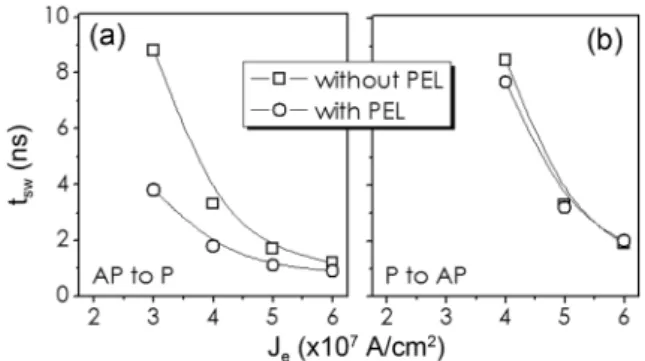
from an antiparallel (AP) state to parallel (P), Fig. 1(a), than for switching from P to AP, Fig. 1(b), because the
magnetostatic field generated from the CmPL (PL) assists the switching of CmFL (FL) in the switching from AP to P, while it disturbs in the switching from P to AP.
The tsw for the switching from AP to P is significantly
reduced by the insertion of PELs, Fig. 1(a), while the tsw
for switching from P to AP remains mostly the same, Fig. 1(b). However, it should be noted that the magnitude of
ST1 is smaller in the case with PEL’s, because the Ms of
the magnetizations adjacent to the MgO layer is larger, and the magnitude of ST1 is inversely proportional to Ms,
as described in Eq. (2). The result that tsw is reduced or at
least retained in spite of the reduction of ST1 indicates
that the existence of PEL essentially assists the CIMS. Because the PEL’s do not have PMA, thus the Top PEL is much more susceptible to excitation. The excitation of the top PEL plays a crucial role in the switching of CmFL, which will be further clarified in the following results on the effect of magnetic property variations. The change in
tsw due to the insertion of PELs is less significant in the
switching from P to AP than the opposite switching because the magnetostatic fields on the Top PEL from other layers are very different between the P state and AP state, and the opposite effect of ST2 according to the
current direction [12].
First, Aex,IL was varied from 10 to 80% of Aex. In that
range of Aex,IL, the PEL magnetizations were
exchange-coupled with PMA layers strong enough to be aligned in perpendicular-to-the-plane direction at the remanent state. The result is demonstrated in terms of tsw, as a function of
Je for various Aex,IL values in Fig. 2. For both switching
directions, tsw increased as Aex,IL increased. The stronger
the Top PEL was exchange-coupled with the FL, the harder the magnetizations are bound in perpendicular direction. Thus, it became difficult for the Top PEL to be excited out of the perpendicular direction. The large Aex,IL
disturbed the switching and subsequently the tsw became
dm dt --- = –γ0m H× eff + αm×---ddtm + ST1 + ST2 ST1 = –γ02---heMP1 sd --- Jem m p×( × ) ST2 = PeM2μB s ---– Jem m×⎝⎛ ×∂---∂zm⎠⎞
Fig. 1.tsw as a function of Je for switching in MTJs with PELs
and without PELs, (a) for the switching of CmFL from AP to P, and (b) for the switching from P to AP. The lines are guides to the eye.
−106− Effect of Magnetic Property Modification on Current-Induced Magnetization… −Woojin Kim, Kyung-Jin Lee, and Taek Dong Lee
longer.
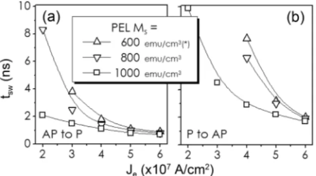
Next, tsw as a function of Je was estimated with
chang-ing Ms of the PELs as shown in Fig. 3. The value of tsw
decreased for both switching directions as Ms increased.
There are several factors that depend on Ms that assisted
or disturbed the CIMS, namely a decrease or increase in
tsw. First, the increase in Ms reduced the magnitude of
ST1, the driving force of the CIMS, as it is inversely
proportional to Ms, as mentioned above. It must disturb
the CIMS so that it results in the increase in tsw. Another
factor depending on Ms was the interlayer exchange field,
which is also inversely proportional to Ms. As observed
from the results in Fig. 2, a decrease of interlayer ex-change coupling assists the CIMS, thus bringing about a decrease in tsw. However, the interlayer exchange field is
decreased by less than a factor of two in the results in Fig. 3. Comparing with the variation of tsw for different Aex,IL’s
in Fig. 2, it is apparent that the decrease in the interlayer exchange field cannot solely induce such significant de-creases in tsw in Fig. 3. The last factor is the out-of-plane
demagnetizing field of the Top PEL that assists the CIMS in the perpendicular direction as it always acts in the
opposite direction to the magnetization. Since its magni-tude is proportional to Ms, the magnetizations with larger
Ms are more easily switched. The decrease in tsw by the
increase of Ms, regardless of the switching direction in
Fig. 3 is attributed to all of those effective factors. The reduction in ST1 is less effective to the CIMS, compared
with the decrease in Aex,IL and the increase in the
demag-netizing field.
Next, the value of tsw was estimated, assuming that the
PELs have small PMA. Fe alloys used for the PEL are generally magnetically soft. However, magnetic anisotropy from the interface can be sizable for such a thin layer considered in this work. PMA was thus introduced into the PELs up to 8×10⁵ erg/cm3, which was 40% of the
PMA in PL and FL, and is equivalent to an anisotropy field of approximately 2667 Oe. The tsw increased through
the increase in PMA for both switching directions as shown in Fig. 4. However, it did not show significant differences when the PMA was on the order of 105 erg/
cm3, the range considered in this work. Moreover, it did
not show much variation from the case of zero-PMA, indicating that the magnetic anisotropy in PELs induced at the interface can be negligible even when the aniso-tropy field is a few thousand Oersted.
4. Summary
We performed micromagnetic investigation on the effects of the magnetic properties on CIMS with PMA and soft magnetic PELs. The decrease in interlayer exchange coupl-ing between FL and PEL reduced tsw. The increase in Ms
of PEL assisted the switching of FL, though the magni-tude of ST1 was reduced. The induced PMA in the PEL
did not make significant variations in tsw when it was on
the order of 105 erg/cm3. Such results should be taken into
account when designing MTJ for MRAM.
Fig. 2. tsw as a function of Je for various interlayer exchange
coupling constants (Aex,IL), (a) for the switching of CmFL from
AP to P, and (b) for the switching from P to AP. The lines are guide to the eye. *Results from default set of parameters.
Fig. 3.tsw as a function of Je for various Ms of PELs, (a) for
the switching of CmFL from AP to P, and (b) for switching from P to AP. The lines are guides to the eye. *Result from default set of parameters.
Fig. 4. tsw as a function of Je for various PMAs (Ku) of PELs,
(a) for switching of CmFL from AP to P, and (b) for switching from P to AP. The lines are guides to the eye. *Results from default set of parameters.
Journal of Magnetics, Vol. 14, No. 3, September 2009 −107−
Acknowledgment
WK and TDL would like to acknowledge the support from the Tera-level Nano-devices (TND) Frontier Project funded by KISTEP. KJL would like to acknowledge the support from the KOSEF through the NRL program fund-ed by the Korean Ministry of Education, Science and Technology (Project No. M10600000198-06J0000-19810).
References
[1] M. Nakayama, T. Kai, N. Shimomura, M. Amano, E. Kitagawa, T. Nagase, M. Yoshikawa, T. Kishi, S. Ikeg-awa, and H. Yoda, J. Appl. Phys. 103, 07A710 (2008).
[2] W. H. Butler, X.-G. Zhang, T. C. Schulthess, and J. M. MacLaren, Phys. Rev. B 63, 054416 (2001).
[3] Y. M. Lee, J. Hayakawa, S. Ikeda, F. Matsukura, and H. Ohno, Appl. Phys. Lett. 90, 212507 (2007).
[4] H. Ohomri, T. Hatori, and S. Nakagawa, J. Appl. Phys.
103, 07A991 (2008).
[5] J. C. Slonczewski, J. Magn. Magn. Mater. 159, L1 (1996).
[6] L. Berger, Phys. Rev. B. 54, 9353 (1996).
[7] J. Z. Sun, J. Magn. Magn. Mater. 202, 157 (1999).
[8] Y. Takeda, T. Umezawa, K. Chiba, H. Shoji, and M. Takahashi, J. Magn. Magn. Mater. 152, 243 (1996).
[9] S. Zhang and Z. Li, Phys. Rev. Lett. 93, 127204 (2004).
[10] A. Thiaville, Y. Nakatani, J. Miltat, and Y. Suzuki, Euro-phys. Lett. 69, 990 (2005).
[11] S. W. Jung and H. W. Lee, J. Magnetics 12, 1 (2007).
[12] W. Kim, T. D. Lee, and K.-J. Lee, Appl. Phys. Lett. 93,