1056
-Abstract - A common DC bus is a useful connection for severalDC output sources such as photovoltaic (PV), fuel cells, and batteries. Operation of the common DC power system with more than two DC output sources, especially in a stand-alone mode, requires a control scheme for the stable operation of the system. In this paper, a control scheme has been developed for applying DC power sources to the distribution system. The purpose of the control scheme is to make the best use of the DC power sources. The DC power system consists of PV, two energy storage systems and a DC-AC inverter with the control scheme. A distribution system was modeled in PSCAD/EMTDC.
As the results, the control scheme is applied to the DC-AC inverter and the DC-DC converter for transfer operations between the grid-connected and the stand-alone mode to keep the DC bus and the AC voltage constant. The results from the simulation demonstrate the stable operation of a grid connected DC power system.
1. Introduction
The increasing energy demand, fast depletion of fossil fuels, along with environmental concerns and the emergence of new electricity market have attracted an interest in renewable energy sources (RES) [1]. In particular, a DC output type RES such as photovoltaic (PV) power generation system and energy storage system (ESS) have been widely used. The DC output type units can be interfaced to a common DC bus with fewer stages of power conversion which can potentially lead to a simpler implementation compared with AC-based integration. A DC bus voltage regulation has to be included in the control algorithms in DC power system and an effective control scheme of the DC power system in distribution system has to be developed as well [2-4].
In this paper, an effective control scheme for applying DC power sources to the distribution system was presented. The DC power system consists of a PV power generation system and ESS connected in parallel to a common DC bus through the DC-DC converters. The common DC bus is connected to a distribution system through a DC-AC inverter which has both the grid-connected and the stand-alone mode. The regulating function of the DC bus voltage in the stand-alone mode and the AC voltage in the grid-connected mode were developed in the control scheme. The DC power system and the distribution system with the control scheme were modeled, simulated and verified using PSCAD/EMTDC.
The control scheme can ensure smooth interchange of the operation modes and keeps the DC bus and the AC voltage constant. The simulation results are presented and discussed in detail.
2. Configuration of a distribution system
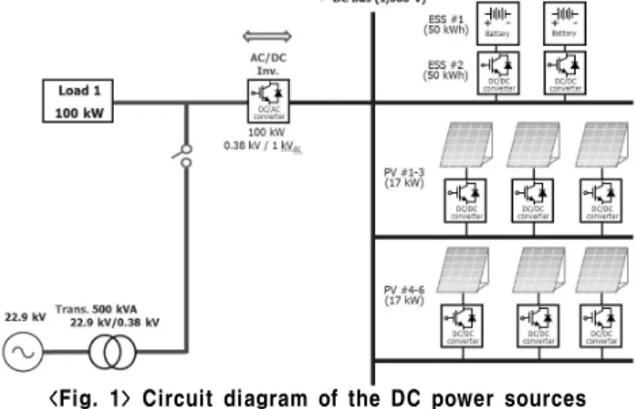
The circuit diagram for DC power sources connected to the distribution system shown in Fig. 1. The systems consist of a PV power generation system 6^EA, ESS 2^EA, an DC-AC converter, load, and utility grid. The DC-AC inverter and ESS DC-DC converters are operated in both grid-connected and stand-alone mode. In the case of the grid-connected mode, the output power of the DC power system is less than a load. The DC bus voltage is regulated by the DC-AC inverter. However, when the DC power system operates in the stand-alone mode, the DC bus voltage can be
regulated by the ESS. The magnitude and frequency of the AC bus are controlled by the DC-AC inverter. The specifications of the DC power sources are shown in Table 1.
<Fig. 1> Circuit diagram of the DC power sources connected to the distribution system <Table 1> Specifications of the DC power sources
3. Design of a control scheme 3.1 DC-AC inverter control
Fig. 2 shows a control block diagram of the DC-AC inverter. The DC bus voltage was kept constant by the voltage controller in the grid-connected mode. In the stand-alone mode, the magnitude and frequency of the AC bus were controlled by the AC voltage controller.
<Fig. 2> The control block diagram of DC-AC inverter 3.2 DC-DC converter control for ESS
The control block diagram of the ESS DC-DC converter is shown in Fig. 3. In the grid-connected mode, the mode select signal is connected to power control. In the stand-alone mode, the DC bus voltage was kept constant by the voltage controller performed using the one ESS. The other ESS was operated by the power control.
배전시스템에 DC 전력원을 적용하기 위한 제어 기법 설계
황철상*, 김경훈*, 변길성*, 전진홍*, 조창희*, 박민원**, 유인근** 한국전기연구원*, 창원대**
Design of a control scheme for applying DC power sources to a distribution system
Chul-Sang Hwang*, Gyeong-Hun Kim*, Gilsung Byeon*, Jin-Hong Jeon*, Chang-Hee Jo*, Minwon Park** and In-Keun Yu** Korea Electrotechnology Research Institute*, Changwon National University**
Items Rated power Number Total spec.
PV 17 kW 6 EA 102 kW
ESS 50 kWh 2 EA 100 kWh
Inverter 100 kW 1 EA 100 kW
Trans. 500 kVA 1 EA 22.9 / 0.38 kV 2015년도 대한전기학회 하계학술대회 논문집 2015. 7. 15 - 17
1057
-<Fig. 3> The control block diagram of ESS DC-DCconverter 3.3 DC-DC converter control for PV
The PV is connected to the DC bus using a DC-DC converter. As shown in Fig. 4, the PV power generation system normally uses MPPT control mode to extract the maximum solar power.
<Fig. 4> The control block diagram of PV DC-DC converter
4. Simulation and the results
For confirming the stable operation of the DC power system in the distribution system, the simulation results of grid, inverter, DC bus voltage, and power of each part are investigated. The gird and inverter voltages are illustrated in Fig. 5 and 6. The inverter kept the AC voltage to the load under the stand-alone mode. Fig. 7 and 8 present the power of each part with PV and load variation. The grid connected mode is changed to disconnected grid for stand-alone mode at 0.5 s.
<Fig. 5> The inverter and grid voltage in mode changed
<Fig. 6> The inverter and grid voltage in mode changed
<Fig. 7> The power of each part with load and PV variations
<Fig. 8> The DC bus voltage and power of ESS The Table 2 shows the simulation scenarios in detail. <Table 2> The simulation scenario
5. Conclusions
In this paper, a control scheme has been developed for applying DC power sources to the distribution system. The control scheme including the regulating function of DC bus voltage in stand-alone mode and AC voltage in grid-connected mode were developed and applied to the DC-AC inverter and DC-DC converter.
The control scheme were verified through a software simulation using PSCAD/EMTDC. The results show that the DC power systems were stably operated in connection with a distribution system. The results will be used for applying DC power sources to a distributed system in the near future.
Acknowledgement
[References]
[1] Navigant Research, “Direct Current Distribution Networks; and Grid-Tied Systems for Data Center Microgrids, Telecom/Village Power, Commercial Buildings, and Military Applications: Global Market Analysis and Forecasts”, 2013.
[2] Gilsung Byeon, Chul-Sang Hwang, Jin-Hong Jeon, Seul-Ki Kim, Jong-Yul Kim, Kisuk Kim, Bokyung Ko and Eung-Sang Kim, “Complementary Power Control of the Bipolar-type Low Voltage DC Distirbution System”, J. Electr. Eng. Technol., vol. 10, no. 3, pp. 786-794, 2015
[3] Daniel E. Olivares, Ali Mehrizi-Sani, Amir H. Etemaemayi, Claudio A. Canizares,Reza Iravani, Mehrdad Kazerani, Amir H. Hajimiragha, Oriol Gomis-Bellmunt, Maryam Saeedifard, Rodrigo Palma-Behnke, Guillermo A. Jimenez-Estevez and Nikos D. Hatziargyriou, “Trend in Microgrid Control”, IEEE Trans. on Smart Grid, vol. 5, No. 4, pp. 1905-1919, 2014
[4] Manoj Lonkar and Srinivas Ponnaluri, “An Overview of DC Microgrid Operation and Control”, International Renewable Energy Congress, pp. 1-6, 2015
This research was financially supported by the Ministry of Education and National Research Foundation of Korea (NRF) through the Human Resource Training Project for Regional Innovation. Items 0.5s 1s 2s 3s 4s 5s 6s 7s Load 30 kW 30 kW 30 kW 70 kW 100 kW 100 kW 35 kW 35 kW PV 0 kW 0 kW 50 kW 50 kW 50 kW 100 kW 100 kW 35 kW ESS1 30 kW +30 kW -20 kW +20 kW -50 kW 0 kW -50 kW 0 kW ESS2 0 kW 0 kW 0 kW 0 kW 0 kW 0 kW -15 kW 0 kW Grid O X X X X X X X