One-step functionally graded materials fabrication using ultra-large
temperature gradients obtained through
finite element analysis of
field-assisted sintering technique
Faris B. Sweidan, Ho Jin Ryu
⁎
Department of Nuclear and Quantum Engineering, Korea Advanced Institute of Science and Technology (KAIST), 291 Daehak-ro, Yuseong-gu, Daejeon 34141, Republic of Korea
H I G H L I G H T S
• A newly designed field-assisted sintering heating geometry that pro-vides ultra-large temperature gradients is proposed.
• Temperature gradients were evaluated for SUS 304L and 8YSZ usingfinite ele-ment analysis.
• The resulting gradients are equal to 80 °C/mm and 122 °C/mm for SUS 304L and 8YSZ, respectively.
• The heating geometry is used to fabri-cate functionally graded versions of the two materials.
• The resulting fabricated samples showed gradual changes in the porosity, grain sizes, and hardness.
G R A P H I C A L A B S T R A C T
a b s t r a c t
a r t i c l e i n f o
Article history: Received 3 March 2020
Received in revised form 21 March 2020 Accepted 2 April 2020
Available online 4 April 2020
Keywords:
Functionally graded materials (FGM) Field-assisted sintering
Finite element analysis (FEA) Stainless steel
Ceramics
Functionally graded materials (FGMs) exhibit good performance owing to their gradual and directional property and compositional changes occurring in the material. Field-assisted sintering is one method to fabricate FGMs by utilizing a heating geometry that provides a temperature gradient within the sample. Here, a heating geometry that provides ultra-large temperature gradients is proposed. Usingfinite element analyses, the geometrical pa-rameters of the proposed design were optimized through a systematic parametric investigation. The resulting temperature gradients were evaluated for electrically conductive stainless steel (SUS) 304L and insulating 8 mol% yttria-stabilized zirconia (8YSZ). The temperature gradients within the samples were 80 and 122 °C/ mm for SUS 304L and 8YSZ, respectively. The heating geometry was used to fabricate functionally graded ver-sions of the two materials, which showed gradual changes in the porosities, grain sizes, and hardness. Lastly, the temperature gradients were then quantitatively validated through temperature measurements and single-temperature sintering experiments.
© 2020 The Authors. Published by Elsevier Ltd. This is an open access article under the CC BY-NC-ND license (http:// creativecommons.org/licenses/by-nc-nd/4.0/).
⁎ Corresponding author.
E-mail addresses:faris.b.sweidan@kaist.ac.kr(F.B. Sweidan),hojinryu@kaist.ac.kr(H.J. Ryu).
https://doi.org/10.1016/j.matdes.2020.108714
0264-1275/© 2020 The Authors. Published by Elsevier Ltd. This is an open access article under the CC BY-NC-ND license (http://creativecommons.org/licenses/by-nc-nd/4.0/).
Contents lists available atScienceDirect
Materials and Design
1. Introduction
Functionally graded materials (FGMs) present a microstructure (po-rosity and grain size) gradient that leads to a gradient in the material properties, such as the density, thermal conductivity, elasticity, and hardness [1–4]. This property gradient provides the possibility of im-proved performance of materials for several applications including arti-ficial bones, spacecraft components, and thermal barriers for turbine engines [2,3]. Recently, FGMs have been extensively developed covering a broad range of materials such as metals and metal alloys [5–8], high entropy alloys [9,10], and ceramics [11–13]. In addition, FGMs also allow for compositional gradients with several possible combinations of materials, which further widen the applications of FGMs.
FGMs can be fabricated through several conventional manufacturing techniques. These techniques include gas-based, liquid phase, and solid phase processes [3]. However, a large portion of these methods require multi-step processes, such as the combination of surface coating tech-niques with mechanical and thermal processes. FGMs can be fabricated through a one-step process using a solid-state approach through the field-assisted sintering technique (FAST), also known as spark plasma sintering (SPS) [12–17]. To fabricate FGMs using FAST, the heating ge-ometry to be used should be designed to provide a temperature gradi-ent within the sample. As a temperature gradigradi-ent is presgradi-ent in the sample, directional densification takes place; the high temperature side experiences higher densification while the low temperature side shows less densification.
Several studies have reported the use of FAST heating elements to sinter FGMs.Fig. 1shows representative example designs that have been reported in previous studies. For instance, Belmonte et al. [13] uti-lized FAST to sinter functionally graded silicon nitride at different tem-peratures that resulted in multi-phase content. Hulbert et al. [14] fabricated dense ceramic matrix composites that contain boron carbide, titanium diboride, and hafnium diboride by FAST. Zhang et al. [15] and Zhang et al. [16] synthesized TiB-Ti and TiB-Ti-TiB2graded systems,
re-spectively, using FAST.
FAST is known to involve complex temperature distributions within the experimental setup that hinder the accurate quantification of the temperature gradient within the sample. Finite element analysis (FEA) has played an important role in understanding and quantifying the tem-perature distributions in FAST as a fully experimental approach is im-possible, due to the high number of correlated parameters and experimental obstacles. Morin et al. [12] utilized the FEA software ABAQUS to quantify the temperature gradient within a 15-mm thick alumina sample and Wei et al. [18] used a multiphysicsfinite element model to investigate the stress and temperature distributions in a Ti-TiB FGM.
However, a large portion of the reported studies did not quantify the temperature gradient that took place within the samples. The
temperature gradients that have been quantified in some of the re-ported studies [12,18] are limited (a maximum of 20 °C/mm) and the heating element designs with the largest temperature gradients require machining of the original FAST heating element design, which may cause stress concentration and failure during the sintering process.
In this study, a heating geometry design that provides extremely large temperature gradients within a 4 mm-thick sample, with minimal changes to the original heating element components shapes, is pro-posed. The temperature profile of the proposed design is then evaluated using FEA to optimize the dimensions of the heating geometry and to quantify the resulting temperature gradients. The optimization process has been conducted through an electrical-thermal FEA parametric in-vestigation. The FEA of the heating element covers two material sys-tems: an electrically conductive alloy represented by stainless steel (SUS) 304L and an insulating ceramic system that is represented by 8 mol% Y2O3-stabilized ZrO2(8YSZ). Thereafter, the optimized heating
geometry is used to sinter functionally graded versions of the two mate-rial systems with graded porosities, hardness, and grain sizes. Finally, the sample temperature gradient results are validated through temper-ature measurements, a series of single-tempertemper-ature sintering experi-ments, microstructural analyses, and hardness measurements. 2. Heating geometry design concept and strategy
To design a FAST heating geometry that provides extremely large temperature gradients within the sample, modifications to the dimen-sions of the original FAST sintering heating element must be imple-mented. The strategy of designing the heating geometry involves generating extreme amounts of heat on one side (the upper punch), while the other side acts as a heat sink. The dimensions and the mate-rials of the heating geometry components must be asymmetrically modified to serve this purpose.
Designing a heating geometry with a portion of its components made of heat-producing materials other than graphite, such as WC-Co [19], is one potential method to create a temperature gradient within the sample. The difference in the thermal and electrical conductivities of the materials affects the heat generation and dissipation within the heating element components that may support the evolution of a tem-perature gradient. However, the electric current capability of the FAST system should be considered when designing the heating geometry with different-heat-producing materials as it may limit the target sintering temperature. As WC-Co has a lower heat producing efficiency compared to that of graphite [19], additional electric current is needed to generate the same amount of heat in the component. To achieve high-temperature gradients and high sintering temperatures in the heating element with a relatively lower electric current, graphite has been selected as the upper spacer, the upper punch, and the die material owing to its high heat-producing efficiency and low cost. WC-Co can be
utilized as the lower spacer and/or the lower punch material to increase the heat transfer and dissipation from the lower side of the heating ge-ometry owing to its higher thermal conductivity compared to that of graphite [19]. The effect of using WC-Co as the lower punch or lower spacer material on the resulting temperature gradient is presented in
Section 3.4.
Designs with edged corners and/or components with varying cross-sectional areas may create non-uniform temperature and stress regions within the heating geometry components and the sample. Cylindrical punches, dies, and samples with unified cross-sectional areas have been adopted in the design to minimize inhomogeneities and to avoid breakage and failure in the heating geometry components.
As mentioned earlier, the FAST system electric current capabilities are of importance when designing the heating geometry. To generate large amounts of heat in the upper punch with relatively smaller amounts of current, the cross-sectional area of the upper punch should be small to increase the current density and the electrical resistance in that specific component [20]. Therefore, punches that have a diameter of 10 mm have been selected. In addition, 4 mm thick samples have been adopted in the design to allow for the observation of the resulting gradient microstructures and experimental property measurements, such as Vickers hardness. However, there are no restrictions on the sam-ple thickness as the temperature increases with increasing the samsam-ple thickness (under the same electric current value). This is due to the in-creased exposed punch length that increases the electrical resistance and, in turn, the temperature. This effect has been thoroughly discussed and presented in our previous work [20]. Therefore, if the amount of powder needed for sinteringfits between the two punches of the heating element, there are no limitations on the sintering of thicker samples.
In addition, FAST allows for the sintering of more complex shapes than onlyflat designs. This can be achieved by controlling the shape of the powder cavity in the heating element. The cavity shape can be mod-ified by controlling the shape of the punches' inner surfaces that are in contact with the powder as well as controlling the die inner hole. This feature is of significance to the FAST-fabricated FGMs potential applications.
To design the heating geometry, a parametric investigation on the heating element geometrical parameters and materials by FEA is con-ducted. The effect of varying the heating element geometrical parame-ters on the temperature of the experimental configuration was thoroughly studied and discussed in the authors' previous work [20]. Thefindings conclude that to produce large amounts of heat in the upper side, the following geometrical modifications must be applied: the use of a long upper punch to increase the electrical resistance in the upper part of the heating geometry, the utilization of a thick graph-ite felt on the top of the die to minimize heat losses, and shifting the sample position upwards, closer to the source of heat, which is the upper punch. Maximizing the heat transfer and dissipation at the bot-tom part of the heating geometry to act as a heat sink can be obtained through the following design modifications: the use of a lower punch with no exposed length (i.e. the bottom punch is entirely inserted in the die), the use of a large die that is in a direct contact with the lower spacer, and applying a thinner graphite felt surrounding the die to in-crease the heat losses from the die side surface relative to the die upper surface.Fig. 2shows the design concept of the heating element. Similar design concept has been proposed by Belmonte et al. [13] and Zhang et al. [16]. However, the geometrical parameters were not opti-mized to provide extremely large temperature gradients and the tem-perature gradients in the reported designs were not quantified.
It is important to note that three aspects must be considered when optimizing the component design. These aspects include that no overheating should occur that may cause sublimation or melting in the heating geometry components; maximum heat transfer and dissi-pation from the lower part of the heating geometry (the heat sink); fi-nally, designing the heating element considering the electric current
capability of the FAST apparatus that is used in the sintering process. Following the design strategy, FEA was conducted as presented in the next section.
3. Finite element analysis
3.1. Theory and electric current application
To simulate the thermal-electrical coupled phenomena that occur in FAST, COMSOL Multiphysics® was used to perform the FEA simulations. These phenomena are governed by the energy and electrical charge conservation equations that are well- studied and reported in [20–22]. The equations are presented in detail in the supplementary appendix.
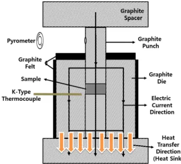
The FAST apparatus that was used in this study is a Dr. Sinter SPS-515S (Japan), with a maximum current output of 1.8 kA. In the FGMs sintering process using FAST, the temperature is monitored through a K-type thermocouple placed in the die wall 2 mm away from the sample bottom surface, as shown inFig. 2. In the FEA simulations, a constant value of the current that provides the prescribed sintering temperature at the thermocouple measurement position is used in a time-independent solution. This current is imposed on the upper surface of the top spacer while a zero electric potential (ground) is applied on the lower surface of the bottom spacer.
3.2. Initial and boundary conditions
The initial temperature condition that was used in the simulation is 27 °C (300K). Two main heat transfer boundary conditions were ap-plied. First, the FAST apparatus is cooled through a heat removal system by water. Therefore, a convectiveflux, Φc, on the upper and lower
hor-izontal surfaces was applied. Second, heat losses by radiation from the lateral surfaces of the spacers, the upper punch, and the graphite felt are the only applicable heat losses as the FAST system operates under vacuum. The equations and the values of the coefficients used in this study, which are reported in [20–25], are discussed thoroughly in the supplementary appendix.
3.3. Materials properties and contact resistances
The materials properties (as functions of the temperature) used in the FGMs sintering process are required for the simulations to be carried
Fig. 2. Heating element design concept for FGMs sintering by FAST (dimensions are not to scale).
out. These properties include the thermal and electrical properties of graphite, the graphite felt, and the sample materials. As reported in the authors' previous work [20], the graphite properties provided by the manufacturer did not result in the successful reproduction of the ex-perimental measurements. Therefore, the graphite properties reported in [26] were used, as they showed the best agreement with the mea-surements that resulted from the experiment. These properties are summarized in the supplementary appendix.
A widely utilized procedure to control the heat loss experienced by the heating element during sintering is to use graphite felt, which is a thermal insulator, around and on top of the die, as shown inFig. 2. The felt acts as a radiation loss barrier, and its low thermal conductivity further insulates the die. The graphite felt properties that are applied in the FEA were obtained from the data available in [27].
The sample materials, as mentioned previously, cover two material systems: an electrically conductive alloy represented by SUS 304L and an insulating ceramic system that is 8YSZ. The electrical and thermal properties of SUS 304L reported in [28,29] and the electrical and ther-mal properties of 8YSZ reported in [30–34] were implemented in the simulations. The properties of the sample materials used in the simula-tion are of fully densified samples. Therefore, the resulting temperature gradients in the simulation represent the minimum values as the tem-perature gradient increases when the porosity increases. The presence of porosity in the sample compact decreases the thermal and electrical conductivity, leading to larger temperature gradients within the sam-ples [35]. However, in this study, the minimum temperature gradients are adopted as they represent the temperature gradients within the samples in the last stages of densification.
The electrical and thermal contact resistances play a significant role in the model accuracy and evaluation of the temperature distribution in the FAST heating element. The electrical and thermal contact resistances between the spacer/punch and the punch/die were obtained from the study by Manière et al. [36] as they showed the best agreement with the experimental measurements. In addition, as two material systems are simulated in this study, the contact resistances between the sample and the die and the sample and the punches were taken into account through the current and heatfluxes across the interfaces. The equations governing thesefluxes and the corresponding coefficients are reported in [18,25,37]. The contact resistance correlations used in the simulations between heating element components are summarized in the supple-mentary appendix.
3.4. Thermal-electrical FEA and the optimized heating geometry dimensions After implementing the required inputs in COMSOL Multiphysics®, as presented thoroughly in [38,39], FEA simulations were conducted fol-lowing the design concept discussed inSection 2to design the heating geometry. In FEA, owing to the symmetry of the experimental setup, one-half of the heating geometry was simulated using the axisymmetric model. A systematic parametric investigation was performed to
optimize the design. Parametric analysis was conducted around a refer-ence geometry that was selected to cover a range of parameter values. In addition, 8YSZ was selected as the sample material, and the temper-ature of the thermocouple position, which is placed in the die wall 2 mm away from the sample bottom surface (Fig. 2), was maintained at 1000 °C while varying the geometrical parameters.
The geometrical optimization process started with evaluating the ef-fect of each geometrical parameter on the sample normalized tempera-ture gradient (temperatempera-ture gradient per unit length) individually. As the heating element is designed to sinter samples that are 4-mm thick and have a diameter of 10 mm, the diameters of the punches were fixed. The dimensions of the spacers do not have a significant impact on the sample temperature compared to other geometrical parameters, as shown in a previous work [20]. Thus, the dimensions of the spacers were keptfixed. The evaluated geometrical parameters include the length of the punches, the die height and width, and the graphite felt thickness. Additionally, the effect of utilizing WC-Co as the lower spacer or the lower punch was evaluated.
A unique characteristic that this heating element design has, com-pared to that of the normal FAST heating element design, is that the main source of heat is the upper punch. This feature makes the upper punch susceptible to overheating, which means that its temperature may approach the sublimation or melting temperatures of graphite. As reported in [40] the sublimation temperature of graphite is around 3800 K. On the other hand, the melting temperature of graphite ranges from 4800 to 5000 K under pressures of 10–100 MPa. Therefore, the upper punch length should be controlled to avoid overheating. The same effect occurs when increasing the lower punch length or decreas-ing the die height as they both lead to an increase in the exposed upper punch length, which increases its electrical resistance and, in turn, its temperature. When overheating happens in FEA, the simulation indi-cates it as the solution does not converge. For these reasons, the upper bounds of the upper and lower punch length were selected to be 28 mm and 24 mm, respectively, while the lower bound of the die height was chosen to be 40 mm. These bounds assure that the heating element still provides extremely large temperature gradients while maintaining the integrity of the experimental setup without overheating.
It is expected that when increasing the die width, the resulting tem-perature gradient within the sample increases as the contact area be-tween the die and the bottom spacer increases, which enhances the heat dissipation at the heating element bottom side. However, an im-portant aspect that should be considered when selecting the die width is the FAST system electric current capability. As the die width increases, the electric current required to reach the thermocouple temperature in-creases [20]. Thus, based on the FEA simulation and multiple experi-ments, the upper bound of the die width has been selected to be 20 mm. This value guarantees that the FAST electric current capabilities allow for thermocouple sintering temperatures above 1200 °C.
After limiting the geometrical parameters that may violate the de-sign strategy, parametric investigations were performed using FEA on
Table 1
The controlled geometrical parameters, the reference values, materials, and ranges, and the resulting normalized temperature gradients.
Parameter Reference values, materials, and range (mm)a
Resulting normalized
Temperature gradients (°C/mm)b
Punches Upper punch length 24, 26, 28 79, 81, 86
Lower punch length 20, 22, 24 74, 81, 90
Die Height 40, 42, 44 91, 81, 72
Width 10, 15, 20 61, 81, 97
Graphite felt thickness Surrounding the die 1, 2, 3 82, 81, 80
On the top of the die 3, 4, 5 78, 81, 82
Material Lower punch Graphite, WC-Co 81, 81
Lower spacer Graphite, WC-Co 81, 82
a
The reference values and material are in bold.
b
the geometrical parameters of the designed heating element.Table 1
shows the ranges of the controlled parameters, the materials, and the normalized temperature gradients for the reference case as well as when varying each of the parameters.
From the results presented inTable 1, the upper or lower bounds of the geometrical parameters that provide the highest normalized tem-perature gradients were used as the optimized heating element dimen-sions. Regarding the graphite felt thickness surrounding the die, a value of 2 mm was chosen instead of 1 mm since the thickness of the graphite felt does not significantly affect the temperature gradient and a slightly thicker felt was easier to handle during the experiment and assured the integrity of the experimental setup during sintering.Table 1shows that using WC-Co as the lower punch or spacer did not result in an increase in the resulting sample temperature gradient as the main heat dissipa-tion component is the die. As a result, the optimized heating element geometry material is selected to be graphite. The optimized design di-mensions are presented inTable 2.
From the FEA thermal-electrical simulation results conducted on the optimized heating geometry, the centerline temperature profiles when SUS 304L and 8YSZ are sintered at a thermocouple temperature of 1000 °C are shown inFig. 3. The resulting temperature gradients in the optimized heating geometry for the case of 8YSZ and SUS 304L are 489 °C and 320 °C, respectively. These values correspond to normalized temperature gradients of 122 °C/mm and 80 °C/mm in 8YSZ and SUS 304L, respectively. The resulting normalized temperature gradients are the optimized and not the maximum values that can be obtained when designing a FAST FGMs sintering heating geometry. The die width can be increased for FAST systems that provide larger electric cur-rent outputs.
In addition, the temperature gradient within the 8YSZ sample shows a larger value compared to that within the SUS 304L owing to the lower thermal and electrical conductivities of 8YSZ relative to those of SUS 304L. Furthermore, SUS 304L, owing to higher electrical conductivity,
permits the current to pass through the powder, which induces Joule heating within the powder itself, and the higher thermal conductivity of SUS 304L allows for heat dissipation to the die, thus reducing the tem-perature gradient. It is shown inFig. 3that the designed heating geom-etry provides extremely large temperature gradients while maintaining the integrity of the experimental setup through a temperature margin for the sublimation or melting of the upper punch. This margin also al-lows for FGM sintering at temperatures higher than 1200 °C without the failure of the heating element, as presented inSection 4.
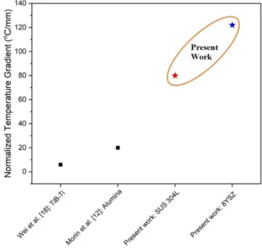
The resulting normalized temperature gradients were compared with the temperature gradients in previous reports where they have been quantified.Fig. 4presents a temperature gradient comparison be-tween the results presented in this study and the results from the quan-tified designs reported in previous studies. The normalized temperature gradients obtained through the proposed design, which are equal to 80 °C/mm and 122 °C/mm for SUS 304L and 8YSZ, respectively, are sig-nificantly larger than the gradients achieved and reported in previous studies (maximum of 20 °C/mm) [12,18]. Additionally, it should be
Fig. 4. The normalized temperature gradient per unit length from the current study and previous studies.
Fig. 3. The centerline temperature profiles of the optimized heating geometry when SUS 304L and 8YSZ are used as samples. Table 2
The optimized heating element dimensions.
Parameter Dimension (mm)
Sample Diameter 10
Height 4
Punches Upper punch length 28
Lower punch length 24
Die Height 40
Width 20
Graphite Felt Thickness Surrounding the die 2 On the top of the die 5
noted that as the thermocouple sintering temperature increases, the temperature gradient increases by ~10 °C/100 °C.
For FAST devices that have higher current capabilities compared to the apparatus used in this study, such as SPS LABOX 650 that has a max-imum current output of 6 kA [41], the heating geometry design can be modified to utilize the higher current capability and to increase the resulting temperature gradient. This can be done, for instance, by in-creasing the die outer diameter. From FEA simulations, these increased temperature gradients can reach up to 170 °C/mm while maintaining the integrity of the heating element. In addition, the higher current ca-pabilities can be utilized to increase the diameter of the resulting
sintered samples up to ~18 mm while achieving the same temperature gradients presented in this study.
4. Experimental procedure: functionally graded materials sintering After designing and optimizing the heating geometry, the resulting heating element was fabricated and used to sinter functionally graded SUS 304L and 8YSZ at three different temperatures. The sintering temper-atures, measured by the thermocouple placed in the die wall, were se-lected based on the reported FAST sintering temperatures of the respective materials and the corresponding temperature gradients that
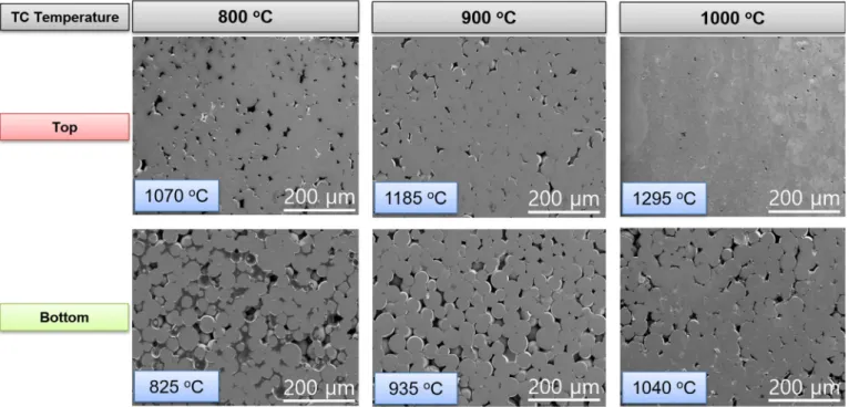
Fig. 6. Scanning electron microscopy microstructure images of the high and low temperature sides of functionally graded 8YSZ grain size after thermal etching. Fig. 5. Scanning electron microscopy microstructure images of the high and low temperature sides of functionally graded SUS 304L.
resulted from the heating elements at a certain thermocouple tempera-ture. According to the FAST sintering temperature of SUS 304L reported in [42–45] and that of 8YSZ reported in [46–50], the selected SUS 304L thermocouple sintering temperatures are 800 °C, 900 °C, and 1000 °C. Further, the sintering temperatures chosen for 8YSZ are 1000 °C, 1100 °C, and 1200 °C. These sintering temperatures allow for a variety of microstructures and porosity distributions within the sintered samples. For sintering, spherical SUS 304L micro powder (Korea powder, 99%, b45 μm), which has a chemical composition of 0.03 wt% C, 2 wt% Mn, 0.045 wt% P, 0.03 wt% S, 0.75 wt% Si, 19 wt% Cr, 10 wt% Ni, and 0.1 wt % Al, and 8YSZ (Sigma Aldrich, 99%,b1 μm) nanopowder, which is ZrO2that has 8 mol% Y2O3as a stabilizing material, were used to sinter
4-mm thick samples. To avoid overshooting, which may lead to overheating in the upper punch during the sintering process, the ther-mal cycle starts with raising the temperature to 700 °C in 7 min (100 °C/min). After, a slower heating rate is applied (20 °C/min) from 700 °C to the target sintering temperature. The dwell time of the sintering process is 5 min and the sintering is performed under a pres-sure of 40 MPa.
It should be noted that the heating rate affects the temperature gra-dient within the sample during heating, as shown by Wei et al. [18]. As
the heating rate increases, the temperature gradient within the sample increases due to the increased current density difference between the two ends of the die. However, the heating rate does not affect the sam-ple temperature gradient when the temperature reaches the target sintering temperature.
One significant aspect that should be addressed here is that, accord-ing to the temperature distribution within the sample that is presented
Fig. 3, the inner part of the sample is considered the most homogeneous and it experiences the largest temperature gradient. Therefore, except for the cases where there is a possibility for the use of an inhomoge-neous sample, mechanical processes should be applied on the resulting sintered samples to extract the central area for thefinal application. 5. Results, discussion, and validation
5.1. Microstructures
After the sintering process, the samples have been polished for cross-sectional microstructural characterization using scanning elec-tron microscopy (SEM, Hitachi SU5000).Fig. 5shows the SEM micro-structural images of the top (the high temperature side) and the
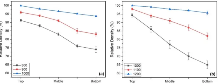
Fig. 8. Relative density of functionally graded (a) SUS 304L and (b) 8YSZ samples. Fig. 7. Relative density quantification of functionally graded SUS 304L sintered at 1000 °C.
bottom side (the low temperature side) for SUS 304L at each of the se-lected sintering temperatures, respectively. The images were taken in the center of the sample. Representative simulation temperatures have been added to each image to indicate the simulated sintering tem-perature of each side obtained from FEA. The simulation temtem-peratures were selected as the 20% average temperatures of the top and bottom sides of the sample. This criterion has been chosen to represent the 10% depth position from each side to account for the grinding and polishing of the sample after the sintering process in addition to the un-certainties in the resulting sintered sample thickness. As shown inFig. 5, microstructural differences are noted between the top and the bottom sides at each sintering temperature in terms of porosity. The top side shows higher densification and less porosity compared to the bottom side. In addition, the degree of sintering increases by increasing the thermocouple sintering temperature. The top part of the 1000 °C sintered SUS 304L sample shows full densification compared to that of lower temperatures. The density quantification of the functionally graded sintered samples is presented inSection 5.2.
The functionally graded 8YSZ samples were selected to evaluate the grain size differences between the top and bottom sides of the sintered samples. The polished 8YSZ samples have been thermally etched at
1000 °C for 2 min followed by SEM microstructural characterization. The resulting SEM images, shown inFig. 6, show that grain size gradi-ents are present between the top and bottom parts of the sintered sam-ples. All the sintered samples show a low degree of sintering at the bottom part with high porosity andfine grain size. However, the top sides of the 1000 °C and 1100 °C sintered samples show a high degree of densification and grain growth is present in the 1200 °C sintered sample.
5.2. Density, hardness, and grain size
For the hardness measurement and the quantification of density and grain size, the cross-sections of the samples were divided intofive parts to cover the whole sample area from the top side to the bottom side. At each part, multiple SEM images (average offive) have been obtained for the quantification of density and grain size, and multiple Vickers hard-ness measurements (average of seven) were conducted. Similarly, the images used for density and grain size quantification and the positions selected for hardness measurements are taken at the center of the sam-ple.Fig. 7shows the density variations and the corresponding SEM im-ages from the top to the bottom of the sample for SUS 304L sintered at
Fig. 10. Grain sizes of functionally graded 8YSZ sintered at 1200 °C. Fig. 9. Micro Vickers Hardness of functionally graded (a) SUS 304L and (b) 8YSZ samples.
1000 °C, which shows a clear density gradient is present in the sample. This density quantification has been performed for all SUS 304L and 8YSZ samples, and the results are shown inFig. 8. In the case of SUS 304L and 8YSZ sintered at 1000 °C and 1200 °C, respectively, a smaller density gradient is seen as the bottom part of the sample is at a high temperature close to that of full densification. On the other hand, at lower sintering temperatures, larger density gradients are observed for the two materials.
The Vickers hardness for all the samples was measured at thefive positions. It is worth mentioning here that as some of the positions within the samples are porous in addition to the presence of a particle size difference between SUS 304L and 8YSZ, the hardness measurement has been optimized and repeated multiple times and on several sintered samples. The hardness measurement optimization was done by control-ling the measurement load that results in controlcontrol-ling the resulting in-dent size. A large inin-dent that covers a large area in the sample was adopted to measure the hardness of the sintered sample not that of the powder particles, especially for the case of SUS 304L sintered at 800 °C and 900 °C. The hardness measurements are shown inFig. 9. Sim-ilar to the density trend, results show a gradient in hardness for all the samples. In the case of SUS 304L sintered at 800 °C and 900 °C, the parts near the bottom of the samples have similar hardness values. The low temperatures experienced by the bottom parts were not suf fi-cient for densification. However, when the temperature increases to-wards the top of the sample, densification starts in different degrees depending on the thermocouple sintering temperature, and the differ-ence in the hardness values increases.
For the case of 8YSZ, large hardness gradients are seen within the sintered samples. For the sample sintered at 1200 °C, similar to the
density behavior, a smaller hardness gradient is present since all the sample parts are almost or fully densified. However, for the samples that are sintered at 1100 °C and 1000 °C, large hardness gradients are present as the temperature gradient is large, compared to that of SUS 304L, and the bottom side of the samples is at lower temperatures than the densification temperatures. Therefore, the hardness values de-crease significantly towards the bottom side of both samples.
As discussed inSection 5.1, 8YSZ was selected to evaluate the effects of the temperature gradient on the grain sizes of the sintered samples. However, the samples that were sintered at 1000 °C and 1100 °C show high porosity. To quantify the temperature gradient effect on the grain size, the grain size of the 8YSZ sample sintered at 1200 °C was evaluated.Fig. 10shows the grain size quantification results along-side the SEM images of the thermally etched sample sintered at 1200 °C. At the bottom part of the sample, the 8YSZ particles start to connect with the presence of large porosities. Moving towards the top side, po-rosity decreases while the grain size is still small (slightly larger than the very bottom of the sample). In the middle of the sample, the porosity disappears entirely and grains start to form. Moving towards the top side, grain growth starts to take place and the grain size increases. How-ever, coarse grain growth, which leads to a decrease in hardness, has not taken place as the temperatures that the top side of the sample experi-ences are only sufficient to induce full densification and a small degree of grain growth.
The error bars inFigs. 7–10represent the standard deviation of the respective properties that resulted from multiple measurements (five to seven measurements). Results show that a gradient microstructure is present from one side to the other side of the sample. This microstruc-tural gradient affected the densities, hardness, and grain sizes of the samples. However, this temperature gradient must be quantitatively validated.
5.3. Validation
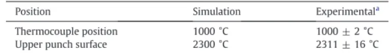
To quantitatively validate the temperature gradients present within the samples, two approaches were followed. These approaches are rep-resented by temperature measurements and single temperature sintering. Temperature measurements were presented by comparing the simulation temperature results with the experimental
Fig. 11. Hardness and microstructure comparison between functionally graded and single temperature sintered SUS 304L. Table 3
A comparison between the simulated and the experimental temperatures at 1000 °C.
Position Simulation Experimentala
Thermocouple position 1000 °C 1000 ± 2 °C
Upper punch surface 2300 °C 2311 ± 16 °C
aTemperatures were measured using the thermocouple and the pyrometer (Fig. 2). The
uncertainty ranges (standard deviation) were determined through multiple measure-ments (average of 12 measuremeasure-ments) during the sintering process.
measurements. On the other hand, the second approach compared the FGMs sintering microstructures and the hardness of samples that were sintered at a single temperature.
During the sintering process, the temperature was monitored through a K-type thermocouple inserted in the die wall 2 mm away from the sample. An optical pyrometer that is focused on a marked loca-tion 3 mm below the contact area between the upper punch and the upper spacer (Fig. 2) was also used to measure the temperature. The py-rometer was used to measure the temperature of the upper punch dur-ing the sinterdur-ing process.
Table 3compares the simulation temperature results with the ex-perimental measurements and it shows that the simulation results are in good agreement with the temperature values obtained from the ex-perimental measurements. However,Fig. 3shows that sintering differ-ent materials at the same thermocouple temperature results in differdiffer-ent temperature gradients within the sample depending on the thermal and electrical properties of the materials. Even though thefirst valida-tion approach provides solid evidence that the simulavalida-tion results match the experimental measurements, the temperature gradient within the sample was still not quantified. The single temperature sintering approach is necessary to precisely quantify and validate the temperature gradients.
The second validation approach compared the microstructures and hardness of the functionally graded samples with samples that were sintered at a single temperature. SUS 304L and 8YSZ samples have been sintered at single temperatures that represent the top and bottom sides of the functionally graded samples. For each FGMs sample, two single temperature samples were sintered, one sample was sintered at the simulated temperature of the top side, while the other sample is sintered at the simulated temperature of the bottom side.
SUS 304L and 8YSZ samples that were sintered at 900 °C and 1100 °C were selected for the validation process. As shown inFigs. 5 and 6, the simulated temperature of the top and bottom sides of the SUS 304L sintered at 900°C are 1185 °C and 935 °C, respectively. For 8YSZ, sintered at 1100 °C, the simulated temperature of the top side is 1485 °C while the simulated temperature of the bottom side is 1115 °C. Therefore, two SUS 304L samples were sintered at 1185 °C and 935 °C while two 8YSZ samples were sintered at 1485 °C and 1115 °C, respectively.
After sintering, the samples were polished and the microstructural SEM images were obtained for all samples. The images were compared with those of the functionally graded samples. The hardness of the sam-ples that have been sintered at single temperatures were also measured and compared with those of the functionally graded samples.Figs. 11 and 12show the hardness and microstructure results of SUS 304L and 8YSZ, respectively. Thefigure shows that the microstructures of the samples sintered at single temperatures are identical to those of the FGM sintering for the top and bottom sides of the samples. However, slight differences are present in the hardness values. For SUS 304L, the hardness value of the functionally graded sample is lower than that of
Fig. 13. The heating element of single temperature sintering and its temperature distribution with and without the measurement hole.
single temperature sintering. For the case of 8YSZ, the hardness value of the single temperature sintering sample is lower than the hardness of the functionally graded sample. The hardness difference in SUS 304L is larger than that of 8YSZ, especially at the top side of the sample.
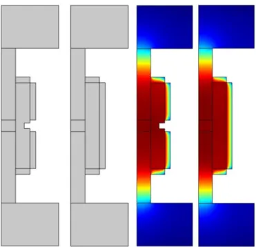
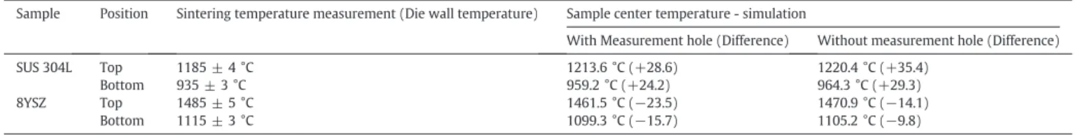
In FAST, temperature control during single temperature sintering is typically based on the readings from a thermocouple or a pyrome-ter that is inserted in or focused on a small hole in the die wall. How-ever, the temperature measured by the thermocouple or the pyrometer is not equal to the centerline temperature of the sintered sample. To confirm this, FEA was conducted on the FAST heating ge-ometry that is used for single temperature sintering. The same FEA methodology, initial and boundary conditions, and material proper-ties that were used previously were applied. Since the heating geom-etry has a measurement hole in the die wall, a small portion of the graphite felt around the measurement points must be removed to allow for these measurements. Therefore, two geometries were sim-ulated, with and without the measurement hole, for the accurate quantification of the temperature distribution.Fig. 13shows the heating geometries that were used for single temperature FAST with their temperature distribution. After conducting the FEA simu-lations, the temperatures of the sample centers were compared with the wall temperature for SUS 304L and 8YSZ, with and without the measurement hole in the die wall. The comparison results are shown inTable 4.
Results show that the temperature of the sample center of SUS 304L is higher than that of the wall temperature in both cases, with and with-out the measurement hole. As SUS 304L powder is conductive and al-lows for current to pass through, Joule heating is induced within the sample, which increases the temperature of the sample. This tempera-ture increase led to slightly higher densification in the sample, which is represented by a higher hardness value for the single temperature sintering case, as shown inFig. 11.
On the other hand, the sample center temperature is lower than the wall temperature for the case of 8YSZ. 8YSZ is an electrically insulating ceramic material and does not allow the electric current to pass through. This leads to a higher temperature in the walls compared to the sample center as the current only passes through the die wall. This temperature decrease in the sample center is reflected in the densification of the sample through a slightly lower hardness value, as shown inFig. 12. Ac-cording to results inTable 4, the temperature difference between the sample center and the wall is higher for the case of SUS 304L compared to 8YSZ. Additionally, the temperature gradient profiles, presented in
Fig. 3, were obtained for fully densified samples without taking into ac-count the presence of porosity in the samples that have been sintered at lower temperatures. Therefore, this assumption also results in slight de-viations in the microstructures and the hardness measurement values.
It is of significance to mention that the difference between the wall temperature and the sample centerline temperature takes place in both geometries, the single temperature sintering and gradient sintering geometries. However, this is valid when, in both cases, the temperatures of the thermocouple or the pyrometer are the points of comparison. For the case of gradient sintering, the temperature values are obtained from the thermal-electricalfinite element analysis in the sample center, not in the thermocouple or the pyrometer position as in the single temperature sintering. Therefore, the difference in the
sample center temperature and the pyrometer position is of importance in the single temperature sintering experiments.
6. Conclusion
Here, a systematically designed FAST heating geometry that pro-vides ultra-large temperature gradients for functionally graded mate-rials fabrication was proposed. The design was optimized and the resulting temperature gradients were evaluated and quantified for sam-ples that are 10 mm in diameter and 4 mm thick throughfinite element analysis. These temperature gradients were also validated through tem-perature measurements and single temtem-perature sintering. The pro-posed design was used to fabricate functionally graded SUS 304L and 8YSZ. Results show a gradient in the microstructure (porosity and grain size) and hardness within the samples.
Large temperature gradients were achieved through a design strat-egy that controls the geometrical parameters of the heating geometry to selectively specify the upper punch to be the main source of heat while the bottom side of the heating element to act as a heat sink. The proposed design provided ultra-large temperature gradients, which were equal to 80 °C/mm and 122 °C/mm for SUS 304L and 8YSZ respec-tively, compared to the temperature gradients obtained through the previously reported designs, which have a maximum normalized tem-perature gradient of 20 °C/mm.
The introduction of ultra-large temperature gradients through FAST allows for the fabrication of a wide range of materials for a variety of ap-plications, including functionally graded structural materials, artificial bones, and spacecraft components. Additionally, the temperature gradi-ent within the sample from designing the heating elemgradi-ent can be con-trolled through the geometrical parameters of the heating element components. This allows for smaller temperature gradients that may be suitable for certain applications that may require fully densified sam-ples (no porosity gradients) with a gradient in the grain size.
Declarations of competing interest None.
CRediT authorship contribution statement
Faris B. Sweidan: Methodology, Investigation, Software, Writing -original draft. Ho Jin Ryu: Conceptualization, Validation, Supervision, Writing - review & editing.
Acknowledgments
This study is supported by High-Risk High-Return Project (HRHRP) of KAIST and the National Research Foundation of Korea grant (NRF-2015R1A5A1037627, NRF-2018M2A8A1083889) funded by Korea Gov-ernment (MSIT).
Data availability
The raw/processed data required to reproduce thesefindings cannot be shared at this time due to technical or time limitations.
Table 4
Comparison between the wall die temperatures and the simulated sample center temperatures.
Sample Position Sintering temperature measurement (Die wall temperature) Sample center temperature - simulation
With Measurement hole (Difference) Without measurement hole (Difference)
SUS 304L Top 1185 ± 4 °C 1213.6 °C (+28.6) 1220.4 °C (+35.4)
Bottom 935 ± 3 °C 959.2 °C (+24.2) 964.3 °C (+29.3)
8YSZ Top 1485 ± 5 °C 1461.5 °C (−23.5) 1470.9 °C (−14.1)
Appendix A. Supplementary data
Supplementary data to this article can be found online athttps://doi. org/10.1016/j.matdes.2020.108714.
References
[1] Y. Wei, Y. Li, L. Zhu, Y. Liu, X. Lei, G. Wang, Y. Wu, Z. Mi, J. Liu, H. Wang, H. Gao, Evad-ing the strength–ductility trade-off dilemma in steel through gradient hierarchical nanotwins, Nat. Commun. 5 (2014) 3580.
[2] I.M. El-Galy, B.I. Saleh, M.H. Ahmed, Functionally graded materials classifications and development trends from industrial point of view, SN Appl. Sci. 1 (2019) 1378.
[3] C. Zhang, F. Chen, Z. Huang, M. Jia, G. Chen, Y. Ye, Y. Lin, W. Liu, B. Chen, Q. Shen, L. Zhang, E.J. Lavernia, Additive manufacturing of functionally graded materials: a re-view, Mater. Sci. Eng. A 764 (2019), 138209.
[4] G. Zheng, Z. Huang, Q. Yu, W. Hu, X. Qiu, A. Lixia, Y. Wang, Y. Jiao, Y. Zhou, H. Zhai, Microstructural and mechanical properties of TiCX–Ni3(Al,Ti)/Ni functionally
graded composites fabricated from Ti3AlC2and Ni powders, Met. Mater. Int.
(2019)https://doi.org/10.1007/s12540-019-00357-5.
[5] X. Wang, Y.S. Li, Q. Zhang, Y.H. Zhao, Y.T. Zhu, Gradient structured copper by rotationally accelerated shot peening, J. Mater. Sci. & Technol. 33 (2017) 758–761.
[6] R. Cao, Q. Yu, J. Pan, Y. Lin, A. Sweet, Y. Li, R.O. Ritchie, On the exceptional damage-tolerance of gradient metallic materials, Mater. Today (2019)https://doi.org/10. 1016/j.mattod.2019.09.023.
[7] L. Yan, Y. Chen, F. Liou, Additive manufacturing of functionally graded metallic ma-terials using laser metal deposition, Addit. Manuf. 31 (2020), 100901.
[8] J.J. Wang, N.R. Tao, K. Lu, Revealing the deformation mechanisms of nanograins in gradient nanostructured Cu and CuAl alloys under tension, Acta Mater. 180 (2019) 231–242.
[9] M.N. Hasan, Y.F. Liu, X.H. An, J. Gu, M. Song, Y. Cao, Y.S. Li, Y.T. Zhu, X.Z. Liao, Simul-taneously enhancing strength and ductility of a high-entropy alloy via gradient hier-archical microstructures, Int. J. Plast. 123 (2019) 178–195.
[10] M.T. Tsai, J.C. Huang, W.Y. Tsai, T.H. Chou, C.-F. Chen, T.H. Li, J.S.C. Jang, Effects of ul-trasonic surface mechanical attrition treatment on microstructures and mechanical properties of high entropy alloys, Intermetallics 93 (2018) 113–121.
[11] D. Tang, L. Hao, Y. Li, Z. Li, S. Dadbakhsh, Dual gradient direct ink writing for forma-tion of kaolinite ceramic funcforma-tionally graded materials, J. Alloys Compd. 814 (2020), 152275.
[12]C. Morin, S. Le Gallet, M. Ariane, F. Bernard, Spark plasma sintering tool design for preparing alumina-based functionally graded materials, Ceram. Int. 42 (2016) 3056–3063.
[13] M. Belmonte, J. Gonzalez-Julian, P. Miranzo, M.I. Osendi, Continuous in situ function-ally graded silicon nitride materials, Acta Mater. 57 (2009) 2607–2612.
[14] D.M. Hulbert, D. Jiang, D.V. Dudina, A.K. Mukherjee, The synthesis and consolidation of hard materials by spark plasma sintering, Int. J. Refract Met H 27 (2009) 367–375.
[15] Z. Zhang, X. Shen, C. Zhang, S. Wei, S. Lee, F. Wang, A new rapid route to in-situ syn-thesize TiB–Ti system functionally graded materials using spark plasma sintering method, Mater. Sci. Eng. A 565 (2013) 326–332.
[16] Y. Zhang, Z. Li, C. Li, Z. Yu, Temperature gradientfield sintering of Ti–TiB–TiB2
func-tionally graded material, Ceram. Int. 41 (2015) 13844–13849.
[17]S. Decker, L. Krüger, Mechanical properties of a CrMnNi steel/Mg-PSZ-FGM proc-essed by asymmetric spark plasma sintering, Mater. Des. 115 (2017) 8–16.
[18] S. Wei, Z.-H. Zhang, X.-B. Shen, F.-C. Wang, M.-Y. Sun, R. Yang, S.-K. Lee, Simulation of temperature and stress distributions in functionally graded materials synthesized by a spark plasma sintering process, Comput. Mater. Sci. 60 (2012) 168–175.
[19]C. Arnaud, C. Manière, G. Chevallier, C. Estournès, R. Mainguy, F. Lecouturier, D. Mesguich, A. Weibel, L. Durand, C. Laurent, Dog-bone copper specimens prepared by one-step spark plasma sintering, J. Mater. Sci. 50 (2015) 7364–7373.
[20] F.B. Sweidan, D.H. Kim, H.J. Ryu, Minimization of the sample temperature deviation and the effect of current during high-temperature compressive creep testing by the spark plasma sintering apparatus, Materialia 9 (2020), 100550.
[21]Y. Achenani, M. Saâdaouia, A. Cheddadi, G. Bonnefont, G. Fantozzi, Finite element modeling of spark plasma sintering: application to the reduction of temperature in-homogeneities, case of alumina, Mater. Des. 116 (2017) 504–514.
[22] COMSOL, MULTIPHYSICS, Version 5.1, COMSOL AB, Stockholm, Sweden, 2015.
http://www.comsol.com.
[23] A. Pavia, L. Durand, F. Ajustron, V. Bley, G. Chevallier, A. Peigney, C. Estournès, Electro-thermal measurements andfinite element method simulations of a spark plasma sintering device, J. Mater. Process. Technol. 213 (2013) 1327–1336.
[24] S. Rothe, S. Hartmann, Field assisted sintering technology, part II: simulation, GAMM- Mitt 40 (2017) 8–26.
[25] K. Vanmeensel, A. Laptev, J. Hennicke, J. Vleugels, O. Van der Biest, Modelling of the temperature distribution duringfield assisted sintering, Acta Mater. 53 (2005) 4379–4388.
[26] C. Manière, A. Pavia, L. Durand, G. Chevallier, K. Afanga, C. Estournès, Finite-element modeling of the electro-thermal contacts in the spark plasma sintering process, J. Eur. Ceram. Soc. 36 (2016) 741–748.
[27] K. Chahine, M. Ballico, J. Reizes, J. Madadnia, Thermal conductivity of graphite felt at high temperatures, Proceedings of 8th Australasian Heat & Mass Transfer Confer-ence (8AHMTC) 2005, pp. 1–4.
[28] C.S. Kim, Thermophysical Properties of Stainless Steels, United States: N. p, 1975https://doi.org/10.2172/4152287Web.
[29]J.C.Y. Koh, A. Fortini, Prediction electrical of thermal conductivity and resistivity of porous metallic materials, Int. J. Heat Mass Transf. 16 (1973) 2013–2022.
[30] A.J. Feighery, J.T.S. Irvine, Effect of alumina additions upon electrical properties of 8 mol.% yttria-stabilised zirconia, Solid State Ionics 121 (1999) 209–216.
[31] M. Ghatee, M.H. Shariat, J.T.S. Irvine, Investigation of electrical and mechanical prop-erties of 3YSZ/8YSZ composite electrolytes, Solid State Ionics 180 (2009) 57–62.
[32]Y. Liu, L.E. Lao, Structural and electrical properties of ZnO-doped 8 mol% yttria-stabilized zirconia, Solid State Ionics 177 (2006) 159–163.
[33] C. Manière, T. Zahrah, E.A. Olevsky, Fully coupled electromagnetic-thermal-mechanical comparative simulation of direct vs hybrid microwave sintering of 3Y-ZrO2, J. Am. Ceram. Soc. 100 (2017) 2439–2450.
[34] L. Wang, Y. Wang, X.G. Sun, J.Q. He, Z.Y. Pan, C.H. Wang, Thermal shock behavior of 8YSZ and double-ceramic-layer La2Zr2O7/8YSZ thermal barrier coatings fabricated
by atmospheric plasma spraying, Ceram. Int. 38 (2012) 3595–3606.
[35] E.A. Olevsky, C. Garcia-Cardona, W.L. Bradbury, C.D. Haines, D.G. Martin, D. Kapoor, Fundamental aspects of spark plasma sintering: II. Finite element analysis of scal-ability, J. Am. Ceram. Soc. 95 (8) (2012) 2414–2422.
[36] C. Manière, L. Durand, E. Brisson, H. Desplats, P. Carré, P. Rogeon, C. Estournès, Con-tact resistances in spark plasma sintering: from in-situ and ex-situ determinations to an extended model for the scale up of the process, J. Eur. Ceram. Soc. 37 (2017) 1593–1605.
[37] A. Zavaliangos, J. Zhang, M. Krammer, J.R. Groza, Temperature evolution duringfield activated sintering, Mater. Sci. Eng. A 379 (2004) 218–228.
[38] J.M. Montes, F.G. Cuevas, F.J.V. Reina, F. Ternero, R. Astacio, E.S. Caballero, J. Cintas, Modelling and simulation of the electrical resistance sintering process of Iron pow-ders, Met. Mater. Int. (2019)https://doi.org/10.1007/s12540-019-00366-4. [39] J.M. Montes, F.J. de la Viña, Í. Agote, T. Schubert, F.G. Cuevas, Y. Torres, J.M. Gallardo,
J. Cintas, Simulation of the electrical resistance sintering of Hardmetal powders, Met. Mater. Int. (2019)https://doi.org/10.1007/s12540-019-00409-w.
[40] A.I. Savvatimskiy, Measurements of the melting point of graphite and the properties of liquid carbon (a review for 1963–2003), Carbon 43 (2005) 1115–1142.
[41] V.A. Kudryashov, S.M. Godin, S.G. Vadchenko, A.S. Rogachev, An experimental appa-ratus for modeling the processes of electric spark plasma sintering, Instrum. Exp. Tech. 63 (2020) 77–80.
[42] S.R. Oke, O.O. Ige, O.E. Falodun, A.M. Okoro, M.R. Mphahlele, P.A. Olubambi, Powder metallurgy of stainless steels and composites: a review of mechanical alloying and spark plasma sintering, Int. J. Adv. Manuf. Tech. 102 (2019) 3271–3290.
[43] I. Sulima, Tribological properties of steel/TiB2composites prepared by spark plasma
sintering, Arch. Metall. Mater. 59 (4) (2014) 1269–1274.
[44] C. Keller, K. Tabalaiev, G. Marnier, J. Noudem, X. Sauvage, E. Hug, Influence of spark plasma sintering conditions on the sintering and functional properties of an ultra-fine grained 316L stainless steel obtained from ball-milled powder, Mater. Sci. Eng. A 665 (2016) 125–134.
[45] N.N. Kumar, G.D.J. Ram, S.S. Bhattacharya, H.C. Dey, S.K. Albert, Spark plasma welding of austenitic stainless steel AISI 304L to commercially pure titanium, T. Indian I. Metals 68 (Suppl. 2) (2015) 289.
[46] X.J. Chen, K.A. Khor, S.H. Chan, L.G. Yu, Preparation yttria-stabilized zirconia electro-lyte by spark-plasma sintering, Mater. Sci. Eng. A 341 (2003) 43–48.
[47] K.A. Khor, L.-G. Yu, S.H. Chan, X.J. Chen, Densification of plasma sprayed YSZ electro-lytes by spark plasma sintering (SPS), J. Eur. Ceram. Soc. 23 (2003) 1855–1863.
[48] K. Rajeswari, M.B. Suresh, U.S. Hareesh, Y.S. Rao, D. Das, R. Johnson, Studies on ionic conductivity of stabilized zirconia ceramics (8YSZ) densified through conventional and non-conventional sintering methodologies, Ceram. Int. 37 (2011) 3557–3564.
[49]K. Rajeswari, M.B. Suresh, D. Chakravarty, D. Das, R. Johnson, Effect of nano-grain size on the ionic conductivity of spark plasma sintered 8YSZ electrolyte, Int. J. Hy-drogen Energ. 37 (2012) 511–517.
[50] X.J. Chen, K.A. Khor, S.H. Chan, L.G. Yu, Overcoming the effect of contaminant in solid oxide fuel cell (SOFC) electrolyte: spark plasma sintering (SPS) of 0.5 wt.% silica-doped yttria-stabilized zirconia (YSZ), Mater. Sci. Eng. A 374 (2004) 64–71.
![Fig. 1. Representative example designs reported in previous studies [ 12 , 14 , 18 ] (dimensions are not to scale).](https://thumb-ap.123doks.com/thumbv2/123dokinfo/5092605.77186/2.892.185.697.856.1088/representative-example-designs-reported-previous-studies-dimensions-scale.webp)