Stress Analysis of pipe supports
H. H. Lee, J. M. Lee, S. K. Park, C.Y. LeeHANARO Utilization Technology Division, 3-Pin Fuel Test Loop R&D Department, Korea Atomic Energy Research Institute, P. O. B 105, Yuseong, Daejeon, 305-353
1. Introduction
The purpose of this study is to describe about the loadings for pipe supports and to maintain functional stability without exceeding appropriate allowables for the pipe support. The design criteria are presented to maintain stability of pipe supports.
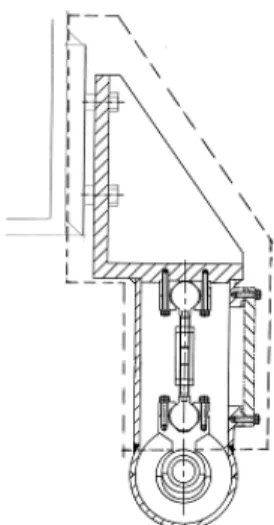
The pipe supports comprise fabricated brackets, bolted to pads which are welded to the existing 254 mm in-pool box beam, which are also welded to the pipe covers. The brackets also support the in-pool piping by means of a turnbuckle and double ball-joint hanger. The boundary between the pipe support and the pipe cover is shown in Fig. 1.
Fig. 1 Piping Support showing Boundary of class 3 Pipe Support
2. Design Requirements for pipe supports 2-1. Safety and Quality Classification
The Pipe Support Brackets are classified as Safety Class 3 and shall be designed and fabricated in accordance with the requirements of Subsection NF for the loads associated with Design, Service Level A, B, C, D and Test Conditions. The Pipe Support Brackets are classified as Quality Class Q and Seismic Category I.
2-2. Service Loadings Level A Service
The Level A Service Loadings, assumed to occur in combination, shall be:
(1) Weight of supported pipe (1” NB schedule 80) including thermal insulation. The weight on each pipe support can be taken as 100 N.
(2) Part-weight of the pipe cover (4” NB Schedule 40), since the weight is shared between the pipe support and the IPS support frame, which can be taken as 644 N for the cold leg pipe support and 672 N for the hot leg pipe support. There are also moments on the supports as follows:
Cold Leg Mx = - 53 Nm My = 0 Mz = 231 Nm Hot Leg Mx = 19 Nm My = 0 Mz = 89 Nm
(3) The vertical load on the turnbuckle resulting from constraint of piping thermal expansion which can be taken as 170 N.
Level B Service
The Level B Service Loadings shall be the following in combination with the Level A service loadings:
(1) Seismic loading from 1 OBE event/year over the design life with 50 cycles per event, to include the loads from 1” pipes and the pipe covers. Loads for the SSE are given below.
Level C Service
The IPS Level C Service condition resulting from a break of the main coolant pipe (hot or cold leg) in Test Room 1 does not generate any additional loading on the Pipe Supports.
Level D Service
The Level D Service Loading, each of which shall be assumed to occur in combination with normal operating conditions (i.e. Service Level A loadings) are:
Transactions of the Korean Nuclear Society Autumn Meeting Busan, Korea, October 27-28, 2005
(1) The load from the 1” pipe is 120 N vertically on the hanger. The loads from the pipe cover can be determined from the weights of the using the following accelerations:
Ax = 3.8 m/s2, Ay = 3.65 m/s2, Az = 1.4 m/s2 (2) The loads developed at the Pipe Supports due to a pipe break at the IPS nozzle pipe weld or at the IPS Hiltap Coupling shall be taken.
Test Conditions
There are no test conditions for the pipe supports. 2-3. Loadings
The following loads may be applied to the pipe supports:
- Pipe weight - Pipe cover weight
- Load resulting from thermal expansion of the pipe - Seismic load from the pipe
- Seismic load from the pipe cover - Reaction due to pipe break
Tables 6 and 7 below summarises the loads used for the analysis which are in all cases conservative enveloping values. The loads are based on the Design Specification, the Piping Design Report and References 4 and 9.
For the Level D in-pool pipe break it is assumed that the maximum transient hydraulic load is applied to the supports due to hanger swinging across and contacting the turnbuckle housing. The Service Level C events, pipe breaks in Room1, do not generate additional load at the pipe supports.
3. Stress Analysis Results
The results for the locations with the smallest margins relative to the code are given in Table. 8 and Table. 9.
Table. 8 Pipe Support Stresses for Service Levels A & B
Table. 9 Pipe Support Stresses for Service Level D
4. Conclusion
Stress results have been presented an allowable stress of pipe supports when applied loads by means of measuring location. Calculated stress is sufficiently lower than the allowable stress values. All these values are lower than the allowable stress.
As a result, it is regarded that pipe supports could maintain its structural integrity for the design loadings and service loadings.
REFERENCES
[1] ASME Design Requirements for Structural steel members, Section III NF-3322, 2001
[2] FTL Pool Penetration Stress Analysis Report, HAN-FL-E-074-RX-H005, Rev. A, 2004.
[3] Design Report for Supports (for IPS & Piping), HAN-FL-E-320-RT-R002, Rev. 0, 2005.
Service Level A(B)
Location Type of
Stress
Calculated
Stress Allowable
Stress ReserveFactor Turnbuckle housing
cover screws Shear 45.7 MPa 63.2 MPa (72.7 MPa)
1.4 (1.6) Tensile 19.9 MPa (175.9 MPa)153.0 MPa (8.8) 7.7 Shear 14.3 MPa (72.7 MPa) 63.2 MPa (5.1) 4.4 M14 Bracket
mounting screws
Combined tensile & shear
3.8 (4.4) F x Fy Fz Mx My Mz Service Leve l A & B 0 - 300 N 0 0 0 0 Service Leve l D 0 -10600
N 0 0 0 0 Table. 6 Loads applied to the Turnbuckle
Fx Fy Fz Mx My Mz
Service Level
A & B 300 N - 1300 N 300 - 250 Nm 0 250 Nm Service Level
D 1050 N -11600N 1050 N - 250 Nm 0 250 Nm
Table. 7 Loads applied to the Bracket of the Pipe Support
Service Level D
Location Type of
Stress
Calculated
Stress Allowable
Stress Reserve Factor Turnbuckle
attachment screws Tensile 87.8 MPa 177.9 MPa 2.0 Turnbuckle
M12 threaded ends Tensile 125.8 MPa 177.9 MPa 1.4 Turnbuckle Tensile 93.1 MPa 177.9 MPa 1.9 Turnbuckle
housing cover screws Shear 67.4 MPa 161.3 MPa 2.4 Tensile 75.3 MPa 268.9 MPa 3.6 Shear 34.2 MPa 161.3 MPa 4.7 M14 Bracket
mounting screws
Combined