62-2 / K. Kim
• IMID 2009 DIGEST
Abstract
A solution processed polymer tandem cell has been fabricated by using the organic layer coated crystalline TiO2 nanoparticle inter layer. The highly dispersive OL-TiO2 has several advantages in terms of excellent film forming property, crystallinity, optical transparency, and well defined chemical composition. The surface morphology of the TiO2 thin film was found to play a crucial role in the performance of the polymer tandem cell. The stability of the tandem cell, utilizing dense TiO2 nanoparticles inter layer, was superior to the stability of the single junction cell.
1. Introduction
The single junction solar cell has limitations to overcome Shockley–Queisser limitation because excess energy of the photons, absorbed with energies greater than the semiconductor bandgap, are lost as heat and photons with energies less than the semiconductor bandgap are not absorbed.1 The tandem solar cell technology could be one way to overcome the limits of the single junction solar cell. However, it is difficult to fabricate polymer tandem solar cells because the previously deposited layer could be destroyed by the following solution process. Therefore, it is important to use a proper separation layer (or inter layer), which isolates two subcells. To achieve the solution processed polymer tandem cell, it is essential to develop solution processed interlayer materials. Semiconducting metal oxides could be promising candidates for the interlayer because they are transparent, are good electron transporters and are insoluble against organic solvents. Gilot et. al., used
ZnO nanoparticles/ PEDOT for the interlayer of the polymer tandem cell.2 However, the netural pH PEDOT was used for the interlayer instead of commercially available acidic PEDOT:PSS solution due to the chemical instability of the ZnO against the weak acid solution. Recently, Kim et. al., successively fabricated solution processed polymer solar cells by utilizing the TiOx/ PEDOT:PSS interlayer, and the
power-conversion efficiency reached more than 6% under the 1 sun illumination condition.3 Thought the TiOx is promising interlayer material for the polymer
tandem cell, the TiOx layer formation needs a
hydrolysis process, which might affect the throughput of the polymer tandem cell production. The nano-crystalline TiO2 nanoparticle (NC-TiO2) could be a
candidate material for the interlayer due to their chemical stability, crystallinity and optical transparency. However, highly dispersive NC-TiO2
solution is essential to form a dense interlayer with smooth surface. In this study, we examined non-aggregated TiO2 nanoparticles solution for the inter
layer of the solution processable polymer tandem cell. The non-aggregated TiO2 nanoparticles are coated
with a thin layer of organic molecules, thus showed an excellent solution processability. 4,5 Such organically modified TiO2 nanoparticles are expected to be a
promising candidate material for the solution processed interlayer due to its excellent film forming property, crystallinity, optical transparency, and a well defined chemical composition.
2. Experimental
The device structure of the polymer tandem cell
Polymer Tandem Solar Cell Having TiO
2Nanoparticle
Interlayer
Won-Suk Chung
1, Hyunjung Lee
1, Wonmok Lee
2, Min Jae Ko
1, Nam-Gyu
Park
1, Byeong-Kwon Ju
3, and Kyungkon Kim
11
Materials Science and Technology Division Solar cell Research Center, Korea Institute of Science and Technology (KIST), Seoul, 136-791 Korea
Tel: 82-2-958-5362, E-mail: kimkk@kist.re.kr
2. Department of Chemistry, Sejong University, 98 Gunja-dong, Gwangjin-gu, Seoul, 143-747 Korea
3. Display and Nanosystem Lab, College of Engineering, Korea University, Seoul, 136-701
62-2 / K. Kim
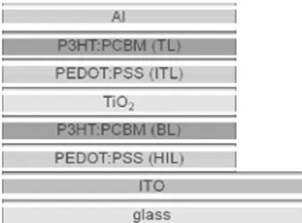
IMID 2009 DIGEST • used in this experiment is glass/ ITO/ PEDOT:PSS
(hole injection layer; HIL)/ P3HT:PCBM (bottom active layer; BL)/ TiO2/ PEDOT:PSS (PH500)
interlayer (interlayer; ITL)/ P3HT:PCBM (top active layer; TL)/ Al (Fig. 1).
Fig. 1. Schematic of the polymer tandem cell
structure with the interlayer of TiO2 nanopaticles
as the electron transport
Two different types of TiO2 solutions have been
examined for the formation of ITL of the polymer tandem cells. The commercially available TiO2
nanoparticle (F-6, Showa Denko, Japan) was dispersed in ethanol solution (N-TiO2 solution), and
used for the ITL of a polymer tandem cell (TC-N). For the other solution, organic layer (acetylacetone, (AcAc)) coated TiO2 nanoparticles (OL-TiO2
solution) were used to form the ITL for another tandem cell (TC-OL). The N-TiO2 solution had
turbid milky color and precipitated after several days. Whereas, the OL-TiO2 solution was highly
dispersive, transparent and stable over six months without any precipitation.
Photocurrent-voltage measurements were performed on the devices, which was determined using a Keithley model 2400 source measuring unit. A class-A solar simulator with a 150 W Xenon lamp (Newport) served as a light source, where its light intensity was adjusted using a NREL-calibrated mono Si solar cell, with a KG-2 filter, for approximately AM 1.5 G one sun light intensity. AFM was used for observing the morphology of the layer. The AFM measurements were carried out on an Asylum Research MFP-3D-SA AFM mounted on AC160-TS cantilever in noncontact mode. The cross-sectional image of the polymer tandem solar cell was taken with the Dual Beam FIB/SEM system (Nova 200, FEI Company), which allows sectional analysis for the cross-section of delaminated region.
3. Results and discussion
Fig. 2. Current density-voltage characteristics of single junction cell (SC) and tandem cells (TC-N and TC-OL) under the AM 1.5G 1sun illumination.
Figure 2 shows the current density-voltage characteristics of TC-N and -OL under the 1sun AM 1.5 illumination. The Voc of TC-N and TC-OL was 0.92 V, and 1.04 V respectively. A single junction cell (SC) was prepared for the comparison, and the VOC
value of the cell was 0.60V. However, the JSC of the
TC-N and -OL were significantly lower than that of the SC. This is because the same light absorbing materials (P3HT and PCBM) were used for the bottom and top cells. The number of absorbed photons, by the top layer, will be significantly smaller than that by the bottom layer. As a result the photocurrent generated from the top layer will be much smaller than that of the bottom layer. It is generally accepted that the JSC of a tandem cell is not larger than the JSC
of two individual cells. It is expected that the low JSC
of TC-N and -OL could be improved when different absorption range materials are used, such as a low band gap polymer and P3HT, for the top and bottom cells. When comparing the photovoltaic properties between tandem cells, the Voc of the TC-OL (1.04 V) was 13% higher than that of the TC-N (0.92 V). Furthermore the JSC of the TC-OL (6.33 mA/cm
2
) was almost twice that of the TC-N (3.24 mA/cm2). The resulting power conversion efficiencies of the TC-N and TC-OL were 1.79 % and 3.44 %, respectively.
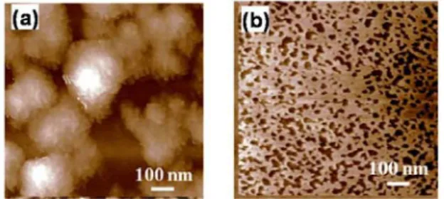
The surface of the interlayer was investigated using atomic force microscopy (AFM) and the AFM images were obtained after spinning the corresponding TiO2 nanoparticles solutions on the
P3HT:PCBM film. As shown in Figure 3, large aggregations (ca. 150 nm – 300 nm) could be observed from the surface of the layer prepared from the N-TiO2 solution. The inset of figure 3(a)
shows that large aggregations are composed of small nano particles (-20 nm). However, no notable aggregation was observed from the surface of the film from the OL-TiO2 solution (Fig. 3(b)). The
62-2 / K. Kim
• IMID 2009 DIGEST
solution was 4.5 nm, which corresponds roughly to monolayer of OL-TiO2 nanoparticles. It is
significantly lower than that of the film from the N-TiO2 solution (29.2 nm).
Fig. 3. AFM image of the film from (a) N-TiO2 and
(b) OL-TiO2 solution.
The height of the OL-TiO2 interlayer film was
around 10 nm and that of the N-TiO2 layer is in the
range of 100-150 nm. However, small voids with size around 30 nm were observed from the OL-TiO2
film. Those voids are thought to be formed during the solvent evaporation. Nonetheless, the size of the voids in OL-TiO2 film is much smaller than that of
voids of the N-TiO2 solution film.
Fig. 4. The Focused Ion Beam (FIB) cross sectional image of the polymer tandem cells (a) TC-N and (b) TC-OL.
The focused ion beam (FIB) image of the TC-OL
(Fig. 4(b)) shows the bottom and top cell are clearly
separated by the OL-TiO2/ PEDOT:PSS interlayer,
while they are physically connected in series to make a complete tandem cell. In contrast, the TC-N does not show a clear layer separation, and large voids (bright region) are observed where the N-TiO2/ PEDOT:PSS ITL is located (Fig. 4(a)). Based
on the AFM and FIB experiments, it is believed that the interfacial contact between the OL-TiO2 and
PEDOT:PSS layer is much better than that between the N-TiO2 and PEDOT:PSS. This implies that the
recombination efficiency at the N-TiO2/
PEDOT:PSS interlayer will be significantly lower than that at the OL-TiO2/ PEDOT:PSS interlayer,
which leads to voltage drop across the interface, and results in a lower VOC of the TC-N.
Interestingly, the tandem cell showed enhanced stability compared to the single cell. The active layers of the cells were covered with commercial epoxy resin in air before the light soaking test. The stability of the cells was monitored by continuous irradiation under a sulfur plasma lamp. The light intensity of the lamp was adjusted using a NREL-calibrated mono Si solar cell with a KG-2 filter, for approximately AM 1.5G one sun light intensity. The temperature of the testing chamber was approximately 35oC. It was found that there was 94% degradation after 125 hours irradiation for the single junction cell, whereas the TC-OL maintained 56 % of its initial efficiency. The degradation is mainly ascribed to the decreased JSC
and FF for both the single and tandem cells. The decline of the JSC and FF of the single cell was much
faster than that of the tandem cell. It is thought that the better stability of the tandem cell is ascribed to the dense TiO2 nanoparticles interlayer, which can protect
the active layer in the bottom cell from the oxygen. Similar results have been reported, where the stability of a cell was enhanced by utilizing the TiOX as an
electron transporting layer.6
4. Summary
In conclusion, a solution processed polymer tandem cell has been fabricated by utilizing the highly dispersive organic layer coated crystalline TiO2 nanoparticles (OL-TiO2)/ PEDOT:PSS inter
layer. The surface morphology of the TiO2 thin film
was found to play a crucial role in the performance of the polymer tandem cell. The power conversion efficiency of 3.66 % was obtained from the tandem cell having the structure of ITO/ low conductive Baytron P VP AI 4083/ P3HT:PCBM/ organic layer coated TiO2 nanoparticles/ Baytron PH500/
P3HT:PCBM/ Al. Furthermore, the stability of the tandem cell utilizing dense TiO2 nanoparticles inter
layer was superior to the stability of the single junction cell. The highly dispersive OL-TiO2 has
several advantages for the solution processed polymer solar cell in terms of excellent film forming property, crystallinity, transparency, well defined chemical composition and processability. It is expected that the performance of the tandem cell can be further enhanced by adopting efficient low band gap materials.
62-2 / K. Kim
IMID 2009 DIGEST •
Acknowledgement
This work was supported by the Korea Institute of Science and Technology (KIST) Institutional Programs (2E20750).
5. References
1. P. Würfel, Physics of Solar Cells, Wiley-VCH, Weinheim, Germany 2004.
2. J. Gilot, M. M. Wienk, and R. A. J. Janssen, Appl.
Phys. Lett., 90, p.143512 (2007).
3. J. Y. Kim, K. Lee, N. E. Coates, D. Moses, T. –Q. Nguyen, M. Dante, and A. J. Heeger, Science., 317, p.222 (2007).
4. E. Kwak, W. Lee, N-G. Park, J. Kim, and H. Lee,
Adv. Funct. Mat., 19, p.1093 (2009).
5. E. Scolan, and C. Sanchez, Chem. Mater., 10, p.3217 (1998).
6. K. Lee, J. Y. Kim, S. H. Park, S. H. Kim, S. Cho, and A. J. Heeger, Adv. Mater., 19, p.2445 (2007).