774
-Abstract - In this paper, a series of electromagnetic analyses carried out for a high efficiency 22.9/0.38kV mold transformer are presented. The simulations were performed in order to calculate the losses which eventually verify the performance(efficiency) of the designed product. Here, losses include core loss, stray losses of non-current carrying metallic structural parts(core plate and clamp), ohmic loss and eddy current loss of current carrying metallic parts(busbars, leads, terminals and windings). The obtained results of the simulations were compared to the test results and showed high level of accuracy. The loss evaluation technology will allow designers avoid any potential over-design or under-design of the high efficiency products, reducing the manufacture cost and development period compared to the conventional experience-based design procedures.1. Introduction
The term 'high efficiency mold transformer' dealt in this paper refers to a mold transformer product group regulated by the energy consumption efficiency standard announced by Korean Ministry of Knowledge Economy that must guarantee a certain level of efficiency under 100°C environment and 50% loading condition. Therefore, accurate loss calculation in designing stage is crucial or designers may end up with over-designed or under-designed product in which both cases lead to weak product competitiveness.
A fully energized and loaded transformer dissipates the following electromagnetic losses: 1) hysteresis and eddy-current losses in core; 2) ohmic and eddy-current losses in windings; 3) ohmic and eddy-current losses leads, terminals and busbars; 4) eddy-current losses in structural metallic parts[1]. Although it is a complex task to calculate hysteresis and eddy-current losses in core separately, it is not difficult to calculate the summed value of the two because this value, which we often refer to as a no-load loss, follows the hysteresis curve and loss characteristic curve provided by the silicon steel plate manufacturer. On the other hand, calculating the sum of other losses, which we often refer to as a load loss, is complex task due to eddy-current losses induced by stray magnetic field which has inherent complex spatial distribution that can not be analytically calculated.
In this sense, studies on eddy-current loss and stray magnetic field simulations and simulation software development have been growing rapidly. The study presents the detailed algorithms for electromagnetic field simulation of a mold transformer that yield the load loss values. Then the verification of these computated values are carried out through comparison with the test results of a real 60Hz 22.9/0.38kV 1,500kVA mold transformer. This loss evaluation technology will be able to replace the previous product development methods based on tests and prototypes.
2. Electromagnetic Field Computation Algorithms 2.1 AC loss coefficient simulation
Current-carrying conductors in a transformer dissipate extra losses due to non-uniform current density distribution which is known as the skin effect. Since this extra loss coefficient calculation remains complex and inaccurate, previous studies have attempted this with experiments. According to the works of Silvester [2] and Dwight[3],
it is most probable to set this coefficient 1.15 for a 100 x 10 mm copper bar with 50Hz current. In this paper, 2D electromagnetic simulations have been carried out on winding, lead, terminal and busbar conductor surfaces. Using the simulated values and the known conductivity and geometry values, DC ohmic loss and AC ohmic loss of current-carrying conductors have been calculated. Figure 1 shows the 60Hz current density distribution of the aluminum conductor surface section acquired by the static solution.
<Figure 1> 60Hz Current distribution in a rectangular conductor
From figure 1, it is evident that current density is concentrated near the top and bottom parts. In widthwise, the distribution appears quite uniform because the width of the conductors used in the model are smaller than or similar to the skin depth of aluminum at 60Hz. HV foil on the other hand, shows uniform distribution because the HV foils used in mold transformers are usually very small, being less than a millimeter thick. In figure 2, the AC loss coefficient curve according to ohm/m and ratio between width and length is presented.
<Figure 2> AC loss coefficient curve 2.2 2D eddy-current analysis
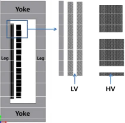
Computing the I²R loss and extra AC loss in conductors can be done quite easily with highly accurate results. It is the eddy-current loss simulation that is complex. Figure 3 shows the 2D axisymmetric model of the transformer dealt in this paper. Even with every turn of the windings is presented, this model is not an exact presentation because the yoke and the outer limb parts are not realistically modeled. However, this error is not significant since the stray magnetic field is confined to the air channel between the LV and HV windings[4]. Computing this model in 3D is not possible due to
전자계해석을 이용한 고효율 몰드변압기 손실 평가기술 연구
정상훈*, 이 곤*, 최명준*
현대중공업*
A study on Loss Evaluation Technology of High Efficiency Mold Transformers using
Electromagnetic Field Simulation
Sang Hoon Chung*, Kon Lee*, Myung Jun Choi*
Hyundai Heavy Industries*
775
-enormous amount of required CPU time and memory.<Figure 3> Transformer 2D model
Figure 4 below presents the simulation results showing the loss distribution. The computed loss values of each turn was subtracted by the ohmic loss computed from the previous processes, yielding eddy-current loss of each turn. As one can see, current density distributions over the LV and HV conductors are not uniform. They are concentrated near the top end of the windings as radial component of stray magnetic flux is present.
<Figure 4> Distribution of ohmic and eddy-current loss over foil windings
2.3 3D nonlinear eddy-current analysis
3D nonlinear eddy-current analysis is carried out in order to compute the eddy-current losses in structural metallic parts. With the MagNet simulation software that allows users to adopt nonlinear B-H characteristics of core and structural parts in time-harmonic solution, realistic condition was modeled. In order to eliminate unnecessary CPU time, surface impedance boundary condition was applied to structural parts. Figure 5 presents the 3D model and the eddy-current loss distribution of the structural parts.
<Figure 5> Distribution of eddy-current loss over the metallic structural parts
Apparently, the losses are concentrated to the end winding regions because the stray magnetic field goes flows mainly to the clamps, and plates through the air region between LV and HV windings.
3. Numerical Results Comparison
In table 1, the simulation results of this study are summarized and compared to the test value of an actual product. The test value is taken as the average of 7 units of the same model: 22.9/0.38kV 1,500kVA.
<Table 1> Results comparison between simulation and test of the 22.9/0.38kV 1,500kVA model
The table shows that the computation algorithm presented in this study generates 6% error in total loss value. This accuracy is very high considering the complexity of the real model compared to the simulation models. However, this is a comparison between two total loss values only not between each loss item. Studies on measurement method of each loss item separately should be carried out in the future.
4. Conclusion
An electromagnetic field simulation algorithms for high efficiency mold transformer loss evaluation technology are presented in this paper. Numerical results were verified through comparison with test results. The accuracy of the total loss value showed 3.52% error. Therefore, a series of electromagnetic field simulations introduced in this paper and their algorithms can be reliable method in designing stage of a high efficiency mold transformer.
[Reference]
[1] S. V. Kulkarni and S. A. Khaparde, "Transformer engineering: Design and practice," in Design and Practice. New York: Marcel Dekker, 2004
[2] P. Silvester, “A.C. resistance and reactance of isolated rectangular conductors", IEEE, Trans. Pow, n6, p.770, 1967
[3] H.B. Dwight, "Effective resistance of isolated nonmagnetic rectangular conductors", Trans. AIEE, Vol 66, p549-552, 1947 [4] Jasmin Smajic, "Numerical Computation of Ohmic and
Eddy-Current Winding Losses of Converter Transformers Including Higher Harmonics of Load Current", IEEE, Trans. Magnetics. Vol 48, 2012
Component Simulation Test Error I²R loss 77.20 75.88 1.33%
Windings 17.18 -
-Leads/Terminals/Busbars 1.69 -
-Clamps/Plates 0.41 -