1. INTRODUCTION
In recent years, the applications of power electronic have grown tremendously. New power electronic systems offer highly nonlinear characteristics. This increase leads to various problems, that some of them are: increased harmonics and reactive power components of the current from AC mains, low system efficiency and a poor power factor. It also causes disturbances to other consumers and interference in nearby communication networks [1].
Traditionally, passive LC filters have been used to eliminate line current harmonics and to improve the load power factor. However but in practice these passive second-order filters present many disadvantages such as aging and tuning problems, series and parallel resonance, and the requirement to implement one filter per frequency harmonics that need to be eliminated [2].
Various solutions have been introduced for eliminating these nonlinearities [3]. Active filters represent various advanced: the aim is to generate a current/voltage which is able to compensate the polluting current/voltage generated by the distorting load [4].
Active filter is considerable challenging with respect to other traditional solutions due to the difficulties in obtaining a good tradeoff performance/cost[1].
In recent years, shunt active power filters, based on current-controlled PWM converters have been widely investigated. They have gradually been recognized as a viable solution to the problems created by high power nonlinear loads [5, 6].
These filters work as current sources, connected in parallel with the nonlinear load, generating the harmonic current that the load requires. In this form the mains only need to supply the fundamental frequency, avoiding contamination problems along the transmission lines.
In this paper a fuzzy logic control of an active filter
realized with a current controlled PWM inverter. The
fuzzy rules choose through the study of the system (distorting load plus active filter) and of its working
conditions.
2. SYSTEM CONFIGURATION
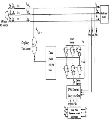
Fig. 1 shows the schematic of the proposed shunt active power filter. The main component of the system is a full bridge switching mode converter built with IGBT's, which is shunt connected to the mains through three phase passive filter. As it can be observed, almost any current-controlled PWM converter can be used as a shunt active power filter, without additional electronic circuitry.
The most important part of designing this active filter is the synthesis of a current reference waveform for the PWM inverters [7]. At the metering section only the current waveforms can be measured, regarding network conditions and load operating condition are responsible for. It is not possible to know any thing about the supply-side or the load side of the same section. Independently from what there is really at the load-side, a load that shows a linear behavior represents an ideal load condition. In fact, if the load under test were linear, the supply system would be the only responsible for the power quality deterioration at the PCC. Therefore, in order to define a current reference, prior to it is necessary to fix ideal load conditions [8].
The reactive power transfer causes phase different between voltage and current waveforms, so it is suitable to consider an ideal linear load as a pure active load. Which can be modeled only with a simple resistor R. this resistor has been calculated supposing that it absorbs only an active power at the fundamental harmonic equal to the fundamental active power really flowing through the metering section. The evaluation of the parameter R allows identifying that part of real load which represents an equivalent linear load and that does not influence the power quality (see Fig. 2)
A Fuzzy Power Control for Three Phase PWM Rectifier with Active Filtering Function
S. H. Hosseini*, M. A. Badamchizadeh** * Islamic Azad University Tabriz branch
(Tel : +98-411-3300819; E-mail: [email protected])
**
Faculty of Electrical & Computer Engineering, University of Tabriz, Email: [email protected]
Abstract: This paper presents a novel fuzzy logic based control method for shunt active filters. Since the fuzzy sets are based on linguistic description, therefore they don’t need to the mathematical model of the investigated systems. The proposed method is very suitable to nonlinear and time variant loads. The controller is robust, reliable and it has a smooth response. Also transient response of method is much better than the other classical methods. The simulation results confirm the suitable performance of the filter using this control method.
Keywords: : Pulse Width Modulation, rectifier, Fuzzy, Harmonic, Power Active Filter
Fig. 1 Proposed shunt active filter topology.
Fig. 2 Nonlinear load connected to the grid. Current components.
This part of the real load absorbs the active current which is ideal current and represents only a part of total current flowing through the metering section. This current has the same waveform of voltage and is always in phase with it.
The parameter R of the ideal load has been calculated by this equation: 1 1 1 1 cos 1 I ϕ V I V R R = = (1)
Where V1 and I1 are the fundamental value of the
voltage and current at the PCC and ϕ1 is the
displacement angle between them. IR1 represents the
part of the fundamental current which is in phase with the fundamental voltage.
The ideal active current is:
R t v t iA ) ( ) ( = (2)
And the reference current is defined as:
)
(
)
(
)
(
t
i
t
i
t
i
REF=
−
A (3)Where v(t) and i(t) represent voltage and current waveform at the PCC before compensation.
Let's consider a traditional current reference:
)
sin(
cos
)
(
)
(
t
=
i
t
−
I
1ϕ
1wt
+
θ
1i
trad REF (4)Where θ1 represents the phase angle of the fundamental
voltage.
It is possible to show that the new current reference has a lower harmonic content. In fact considering the Fourier series of the voltagev(t), it can be shown:
= − = R t v t i t iREF() () ()
∑
∞ = = + − 1 ) sin( ) ( k K k kwt R V t i θ∑
∞ = = + − 1 ) sin( ) ( k K Rk kwt I t i θ∑
∞ = = + − 1 ) sin( cos ) ( k K k k kwt I t i ϕ θ ) sin( cos ) sin( cos ) ( 2 1 1 1 k k k K kwt I wt I t i − ϕ +θ −∑
ϕ +θ ∞ = ) sin( cos ) ( 2 k k k K REF t I kwt i trad − ϕ +θ =∑
∞ = (5)Since the principle of superposition can be applied.
3. REFERNCE CURRENT CALCULATION
To design the control system and harmonic reference current generator, the dq transformation method is used to achieve harmonic cancellation. The following three element matrix vectors are expressed by using dq transformation matrix T(θ) and inverse dq transformation matrix T−1(θ) dq abc abc dq T f f T f f = (θ) = −1(θ) , (6) Where the f variable denotes the current or voltage quantities and the transformation matrix is given as,
⎥ ⎥ ⎥ ⎥ ⎥ ⎥ ⎥ ⎦ ⎤ ⎢ ⎢ ⎢ ⎢ ⎢ ⎢ ⎢ ⎣ ⎡ + − + − = 2 1 2 1 2 1 ) 3 2 cos( ) 3 2 cos( ) cos( ) 3 2 sin( ) 3 2 sin( ) sin( 3 2 θ θ π θ π π θ π θ θ T (7)
Fig.3 shows a technique taking dq transformation from stationary to synchronous reference frame and having low pass filters to obtain average values. A low pass filter can eliminate all harmonic currents except dc component. This component used for fundamental current calculation.
The three phase nonlinear load currents can be expressed as follows, The detail equations for phase-a are derived.
∑
≠ − + = + = 1 1 1 1 ) sin( 2 ) sin 2 h ah h a a a h a a a hwt I I i i i β β (8 ) Where 1 a i is a fundamental component, h a i (h=1,2,3,…) is a harmonic component such as 3rd, 5th, 7th, etc on the stationary abc frame, and ha a β
β1 ,
are the displacement power factor angels for fundamental and harmonics, respectively. Taking the dq transformation for the above currents, abc T c b a T e n e q e d e dq i i i T i i i T i i =[ ] = (θ)[ ] = (θ) (9 )
D and Q components on the synchronous reference frame are separated as,
⎥ ⎥ ⎦ ⎤ ⎢ ⎢ ⎣ ⎡ + + + + = ⎥ ⎥ ⎦ ⎤ ⎢ ⎢ ⎣ ⎡ = e c q e b q e a q e c d e b d e a d e q e d e dq i i i i i i i i i , , , , , , 3 2 (10)
Again each component is divided into fundamental and harmonic components as,
h h e j q e j q e j q e j d e j d e j d i i i i i i , , , , , , 1 1 + = + = (11) Where 1, e j dq
i (j=a, b, c) comes from the fundamental component 1
j
i and eh j dq
i , from the harmonics
h j
i . In [10] S. Kim shows the reference current calculated by:
× − + + = 3 2 ) ( 3 2 , , , 1 dc c d dc b d dc a d e d I I I i + − + tan(2 ) ( Iddc,a2 Iqdc,a2 wt βa1 (12) + − + + ) 3 2 2 tan( , 2 1 2 , b dc b q dc b d I wt I π β )) 3 2 2 tan( , 2 1 2 , c dc c q dc c d I wt I + − π −β × − + + = 3 2 ) ( 3 2 , , , 1 dc c d dc b d dc a d e q I I I i + − + + ) 2 2 tan( ( , 2 1 2 , a dc a q dc a d I wt I π β + − + + ) 6 7 2 tan( , 2 1 2 , b dc b q dc b d I wt I π β )) 6 1 2 tan( , 2 1 2 , c dc c q dc c d I wt I + − π −β (13)
Where Idqdc denote dc component of e
j dq
i , . The dc component can be obtained through a simple first order low pass filter. A displacement power factor angle obtained as: ⎟ ⎟ ⎠ ⎞ ⎜ ⎜ ⎝ ⎛ − = − dc j d dc j q i j I I , , 1 tan β (14)
Fig. 3Block diagram of estimate reference current.
4. FUZZY LOGIC BASED CONTROL TECHNIQUE
Fuzzy logic has rapidly become one of the most successful of today's technologies. It offers a methodology for handling of qualitative, inexact and imprecise information in a systematic and rigorous way. Fuzzy logic based controllers can be employed with good results if the system to be controlled has unknown, ill-defined or non linear dynamics. Unlike in usual control methods, the design and tuning of a fuzzy based controller doesn't need establishing any mathematical model of the controlled plant. On the contrary, what we need to design fuzzy logic algorithms are understanding the mechanics behind a behavior of the controlled system, end identifying the system dynamics in terms of measure of input/output changes are essential parts of the fuzzy algorithms design [9].
Fuzzy logic may serve as a very effective tool to handle some of PWM inverters and electrical drivers because they have discrete time varying and/or nonlinear dynamic mathematical representation.
The internal structure of the fuzzy controller is shown in Fig. 4. Here, the input variables are the current error and slope of the reference current. To convert these numerical input variables into linguistic variables, the
h abc i - 1 abc i Idc Dc quantity calc. Fundamental phase current calc. DQ Trans. iabc
following four fuzzy levels or sets are chosen as: NL (negative large), NS (negative small), PS (positive small), PL (positive large).
The fuzzy controller is characterized as follows:
1- Four fuzzy sets for each input and five fuzzy sets for output.
2- Bell shape membership functions
3- Fuzzification using Gaussian curve membership function
4- Implication using Mamdani's 'min' operator. 5- Defuzzification using the 'centroid' method. The output variable is the duty cycle that defines the sampling period portion assigned to the first switch driven in respect of the full sampling period. The fuzzy labels chosen to define the duty cycle are very small (VS), small (S), medium (M), big (B) and very big (VB).
Fig. 4 Internal structure of the fuzzy controller.
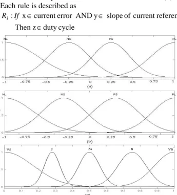
Fig. 5 shows the normalized bell membership functions used in fuzzification.
The set of fuzzy control rules is shown in Table (1). Each rule is described as
cycle duty z Then reference current of slope y AND error current x : ∈ ∈ ∈ If Ri
Fig. 5 Normalize membership function. a: current error b: slope of reference current c: Duty
cycle.
Table (1) Fuzzy rules for duty cycle.
Current error Duty cycle NL NS PS PL NL VB V VS VB NS VB M S VB PS VB S M VB Reference Current slope PL VB VS B VB 5. SIMULATION RESULTS
Fig. 6 shows the system configuration of the three phase PWM rectifier with the function of active power filter.
The parameters of the system analyzed were:
mH L mH L R V V c s s srms 66 . 0 , 1 . 0 R : filter Passive , 5 . 0 , 1 . 0 , 220 : main c = Ω = = Ω = =
Fig. 6 System configuration of the three phase APF-PWM rectifier.
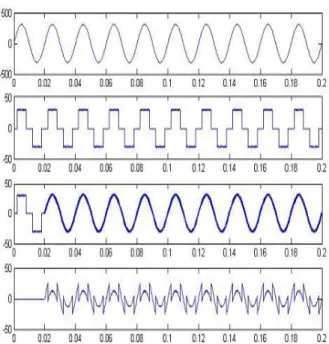
Figs (7), (8) Show the simulation results of the proposed shunt active power filter controlled by fuzzy logic. Fig. (7) shows the response of the fuzzy controller: The main Voltage (Vsa), The load current (Ila) and source current (Isa) and filter current (Ifa) are presented here. The filter is switched on at 20ms.
The harmonic contents for load current and source current are shown in Fig. (8).
Referenc e currents Fuzzification Decision Making Defuzzification Slope of ref. Current Load currents To PWM Rectifier
Fig. 7 Switch-on response of fuzzy logic controlled shunt active filter.
Fig. 8 Normalize Harmonic contents for load and source currents.
6. CONCLUSION
In this paper, three phase active power filters with fuzzy logic control are introduced. This novel control has a high accuracy, good speed and provides a faster response to fast load changes. The proposed control
method eliminates the need of calculating the harmonics and reactive current components. This technique only needs to sense the three phase load currents. It can be seen that performance of the filter don't affect by the supply distortion and source currents are nearly sinusoidal after compensation. The proposed system tested using computer simulations.
REFERENSES
[1] Jain, S.K.; Agrawal, P.; Gupta, H.O.;" Fuzzy
logic controlled shunt active power filter for power quality improvement", Electric Power Applications, IEE Proceedings, Vol. 149 ,Issue 5 , Sept. 2002, pp: 317 – 328.
[2] Dixon, J.W.; Contardo, J.M.; Moran, L.A.;"A fuzzy-controlled active front-end rectifier with current harmonic filtering characteristics and minimum sensing variables", IEEE Transactions on Power Electronics, Vol. 14 , Issue: 4 , July 1999, pp:724 – 729.
[3] W. Jewell, "Power quality laboratory testing", IEEE power engineering Review, Vol. 22, No. 2, February 2002, pp. 13-15.
[4] B. Sing, K. Al-Hadad, A. Chandra, " A review of active filters for power quality improvement", IEEE Trans. on Industrial Electronics, Vol. 46, No. 5, October 1999, pp. 960-971.
[5] W. M. Grady, M. J. Samotyj, A. H. Noyola, "survey of active power line conditioning methodologies", IEEE Trans. Power Delivery, Vol. 5 , July 1990, pp. 1536-1542.
[6] L. Malesani, L. Rosseto, and P. Tenti, " Active filters for reactive power and harmonic compensation," in Proc. IEEE PESC'86, June 1986, pp.321-330.
[7] Dell'Aquila, A.; Lecci, A.; Monopoli, V.G.; "Fuzzy controlled active filter driven by an innovative current reference for cost reduction", Proceedings of the 2002 IEEE ISIE, Vol. 3, 26-29 May 2002, pp. 948 – 952.
[8] A. Dell'Aquila, M. Marinelli; V. Monopoli, P. Zanchetta. " New indices to evaluate the quality of the power absorbed by a nonlinear load" Proc. of 9th European Conference on power electronics and applications, Graz (Austria), August 2001. [9] Lee, C. C. "fuzzy logic in control systems: fuzzy
logic controller – part I, II", IEEE Trans. on SMC, Vol. 20, No. 2, 1990, pp: 404-435.