Heat flux test with the HIP bonded mock-up of Cu/SS for the ITER first wall
a)Dong Won Lee, Young Duk Bae, Bong Geun Hong, and Jong Hyuk Leea)Korea Atomic Energy Research Institute
Deokjin-dong, Yuseong-gu, Daejeon, 305-600, Republic of Korea E-mail: [email protected]
1. Introduction
The first wall (FW) of the International Thermonuclear Experimental Reactor (ITER) is the important component facing the plasma directly and therefore, it is subjected to high heat and neutron loads. The FW is composed of a beryllium (Be) layer as plasma facing material, a dispersion-strengthened copper (DS-Cu) layer as a heat sink and type 316L authentic stainless steel (SS316L) as structure material. To fabricate the FW, the hot isostatic pressing (HIP) bonding method has been proposed. Surface heat flux of the FW is about 0.3 MW/m2 and volumetric heating
in the FW is in the order of 15-20 MW/m3 due to
neutron wall loading [1]. To investigate the thermo-mechanical performance of the FW, including the integrity of the HIP bonded interfaces, a high heat flux test is required. Since the Cu/SS mock-up will be tested in JAERI electron beam irradiation stand (JABIS) without Be layer, the HIP bonded mock-ups of Cu/SS and the preliminary heat flux test facility were prepared. And more, the analysis was performed with ANSYS 9.0 to determine the test condition.
2. Preparation of Cu/SS mock-up
The optimum joining condition of a HIP for ITER FW has been developed using Be of S-65C grade, CuCrZr and DS-Cu, and SS316L. Here, CuCrZr/SS316L and DSCu/SS316L mock-ups were fabricated to investigate their integrity through the several tests. They were successfully HIPped at 1050
OC, 2 hr and 100 to 150 MPa. Microstructure
observation and mechanical tests were performed to confirm the joining technology [2].
The schematic and thermocouples installation of mock-up were shown in Figs. 1. Dimensions of the mock-up are 101 mm long, 50 mm wide and 31 mm thick with two circular cooling tubes. Five thermocouples are installed to measure the temperature in the mock-up according to the distance from the heat source. Two manifolds and connected pipes were prepared for the coolant.
3. Heat flux test facility
As mentioned before, JABIS will be used as a high heat flux test facility for the Cu/SS mock-ups because there is no high heat flux test facility in Korea. Before the high heat flux test with JEBIS, the preliminary test is prepared as shown in Fig. 2. A heat source is the halogen lamps (1kW, 2EA). With the heat flux sensor
(Vatel Corporation TG1000-1A), heat flux from heat source was measured according to the distance from the halogen lamp and the power supply voltage. As shown in Fig. 3, the test results shows that the maximum heat flux is 150 kW/m2 at the distance of 2 cm and power
supply voltage of 190 V.
Figure 1. Schematic of the Cu/SS mock-up and TCs installation
Figure 2. Schematic and picture of the KAERI heat flux test facility with halogen lamp
Transactions of the Korean Nuclear Society Autumn Meeting Busan, Korea, October 27-28, 2005
Figure 3. Measured heat flux from the KAERI test facility according to the distance
4. Preliminary Analysis
The objective of the present heat flux tests is to examine the integrity of the HIP bonded interface under high heat flux conditions and also to examine the fatigue lifetime and the facture behavior of the FW mock-ups. Preliminary analyses were carried out to specify test conditions and also to predict the fatigue lifetime of the pane. The analysis used 2-dimensional modeling as shown in Fig. 4. A uniform heat flux was applied on one side, while the temperature and the velocity of the cooling water were 25 OC and 7.0 m/s,
respectively, as indicated in Fig. 4.
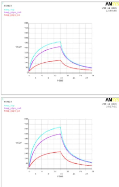
The calculated temperature distribution of the mock-up, at the heat flux loading duration of 15 s and under each heat flux condition, is shown in Fig. 5. Under a heat flux of 5.0 MW/m2, the maximum temperature at
the front surfaces, at the HIP bonded Cu/SS interface and at the inner surface of the SS cooling tubes were 507, 426, and 205 OC, respectively. Similarly, under a
heat flux of 7.0 MW/m2, temperatures at each region were 676, 565, 273 OC, respectively. In both cases, the
maximum strain at the inner surface of the cooling tubes and the values are shown in Table 1. And more, from the fatigue-constant strain curve, the test cycles were determined [4]. Figure 6 shows the temperature response under the heat flux of 5.0 MW/m2 and 7.0
MW/m2, respectively.
5. Conclusions
The HIP bonded mock-up of Cu/SS for ITER FW and the preliminary heat flux test facility are prepared and preliminary test and analysis are performed. The analysis results and further experimental results will be used when the mock-up is test in JEBIS.
REFERENCES
[1] A. Cardella, et al, Technical Basis for the ITER EDA plasma facing components, Fusion Eng. Des. 39-40 (1998) 377-384
[2] J. Y. Park et. al., “Optimization of joining condition for ITER first wall fabrication,” 5th Asia Plasma Fusion
Association, Jeju, Korea, Aug. 2005,
[3] T. Hatano et. al., “High heat flux testing of a HIP bonded first wall panel with built-in circular cooling tubes,” Fusion Eng. and Des., 39-40, pp 363-370 (1998)
[4] ITER Material Properties Handbook, File code : ITER-AA02-2402
Figure 4. Analysis model of ANSYS 9.0
507 C 426 C 205 C DS-Cu SS 316L [ 5 MW/m2 ] 676 C 565 C 278 C DS-Cu SS 316L [ 7 MW/m2 ]
Figure 5. Results of thermal analysis under each heat flux
Figure 6. Temperature response under each heat flux
Table 1 Maximum strain and calculated cycles at each test case
Cases 5 MW/m2 7 MW/m2 Max. strain 0.94 % 1.25 %
cycles 1800 1000 Uniform Heat flux
SS316L DSCu