A CASE STUDY OF GROUND CAVE-IN DUE TO SUBSURFACE EROSION IN OLD LAND FILL
113
A CASE STUDY OF GROUND CAVE-IN DUE TO SUBSURFACE EROSION
IN OLD LAND FILL
REIKO KUWANOi)and YUKIHIRO KOHATAii)
ABSTRACT
Ground cave-in is usually initiated by the formation of cavity within the ground due to soil loss. When the location of the cavity is deep in the ground, the detection of the cavity is not easy. Then it is possible that the hidden cavity expands for a long time to eventually cause sudden large-scale collapse.
A case of large scale ground collapse in the old fill ground was studied and described in this paper. The underground cavity appeared to be caused by subsurface erosion deep in the ground and to expand/extend upward till it was ended by the catastrophic ground failure. It highlighted the importance of proper drainage work in a large scale land fill.
Key Words : Subsurface erosion, Ground cave-in, Soil pipe, Volcanic ash
1 INTRODUCTION
A sudden collapse of the ground occurred in the 8th fairway at the Le Petaw golf course in Hokkaido on April 2, 2009, when a woman golfer unfortunately stepped on it. She fell into a hidden hole formed underneath the ground and by the time a rescue team arrived she had passed away.
The hole was 5m deep and 7m wide at the bottom. Although the golf course was daily checked by maintenance staffs, they could not get any sign of the hidden hole even in the morning of the accident. The ground collapse seemed to have happened all of sudden, as the victim’s son who walked just a couple of meters behind her saw her suddenly disappearing into the ground.
A detailed investigation took place by Hokkaido prefectural police, assisted by the authors. This paper reports findings in the investigation, based on which the mechanism of the hidden cavity formation is discussed.
2 OUTLINE OF THE COLLAPSE 2.1 Topography and ground condition
The golf course was originally built more than 15 years ago in hilly land, by filling a valley with local soil. The ground consists of mud rock covered with silty volcanic ash. The thickness of the land fill seems to be 10 to 15 meters. The surface layer of about 0.5m was added fertile soil for the growth of lawn. It is a gentle slope in the 8th fairway and there used to be a stream
along the east-west direction at the location of the collapse. Although the exact locations are not identified, drain pipes should have been installed underground to carry away the subterranean water while preventing soil from seeping out. There are several artificial ponds around the fairway for water hazards in the course, as shown in Figure 1. When the accident occurred, the ground water level was considered to be higher than usual, as it was the spring snow-thawing season.
Figure 1. Photo at the location of collapse (after Asahi Newspaper 090417)
I) Associate Professor, Institute of Industrial Science, the University of Tokyo, Komaba 4-6-1, Meguro-ku, Tokyo, 153-8505, Japan.
ii) Associate Professor, Department of Civil Engineering and Architecture, Muroran Institute of Technology, Mizumoto-cho 27-1, Muroran, 050-8585,
JAPAN.
The 8th fairway
collapse
N
REIKO KUWANO and YUKIHIRO KOHATA
114 2.2 Underground cavity
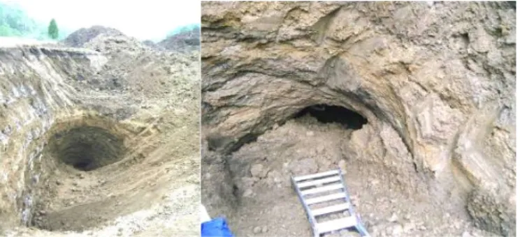
The hidden hole had a flask shape with a 1 m wide opening at the ground surface (see Figure 2), and was 5m deep and 7m wide at the bottom. There was an about 0.6m deep shallow water pool in the east side of the hole, and the water flew to the west direction. Noticeable erosion was found in both west and east sides at the bottom as schematically shown in Figure 3.
Figure 2. Opening at the ground surface (from Hokkaido Newspaper)
Figure 3. Schematic of the underground cavity The volume of the soil for the hole is about 75m3. One of the questions is that where such amount of soil went. There is a water reservoir in the down stream of the 8th fairway, where large amount of soil sediment was found. It may be the possible destination of the soil flown from the hole.
3 INVESTIGATION BY EXCAVATION
A large scale excavation was carried out around the hole to understand how and why such a huge underground hole was created. Soil sample was taken from three locations to characterize their physical properties.
3.1 Soil pipe discovered beside the hole
Figure 4 is a photo of excavation. Excavated soil was a mixture of volcanic clay, silt, sand, and relatively small gravel, as shown in Figure 5. Roots of plants
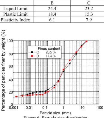
were also included, which indicates the excavated strata were filled soil. Atterberg limits and particle size distribution are shown in Table 1 and Figure 6, respectively.
Figure 4. Excavation around the hole
Figure 5. Soil in the excavated wall (GL-approx.6m) Table 1 Atterberg limits of soil sample taken from the hole
B C
Liquid Limit 24.4 23.2
Plastic Limit 18.4 15.3
Plasticity Index 6.1 7.9
Figure 6. Particle size distribution
At the depth of 8m from the ground surface, there was the boundary between original stiff ground and filled soil, where a lateral ground cavity of about 2m
7m 5m 1~1.5m East West water pool water flow erosion erosion 細粒分含有率 C 20.5 % B 17.4 % P erc en ta ge of p arti cles fi ne r b y w eig ht ( % ) Particle size (mm) Fines content 0.0010 0.01 0.1 1 10 100 20 40 60 80 100 5m Location of opening at ground surface East West Plant root
Sand with high water content
A CASE STUDY OF GROUND CAVE-IN DUE TO SUBSURFACE EROSION IN OLD LAND FILL
115 wide was discovered in about 20m west from the center of the hole, as shown in Figure 7. The sound of water flow was clearly heard in the cavity. The length of the cavity was at least 6m, but could not be confirmed as the further excavation was not conducted. It seemed to be a path through which soil with water was transported out of the hole.
Figure.7. Natural soil pipe due to the internal erosion
3.2 Search for the destination of the water flow in the soil pipe
Water colored by fluorescent paint was poured into the cavity to search for the destination of the water flow in the soil pipe. After 20 minutes, the colored water started flowing out at the reservoir, 700m down from the cavity. It can be considered that a soil pipe is formed in the ground between the collapsed location and the reservoir where a large amount of soil sediment was found.
3.3 Location of the water inflow
In the excavation on the east side, the point where the water flew into the hole was found at about 10m away from the center (Figure 8). It was indicated that the hidden hole was formed on the subsurface water stream.
Figure 8. Water inflow at the east side of the hole
4 ESTIMATION OF UNDERGROUND CAVITY FORMATION
Comparison between old and current map of the location revealed that the ground collapse occurred at the land fill exactly on the old stream, as shown in Figure 9. The locations of the water inflow and outflow were identified at east and west side of the hole respectively.
Figure 9. Location of the old stream
Ground appeared to be internally eroded by the natural water path formed at the old stream. It is like a natural drainage pipe, so that it is generally called soil pipe. As the erosion of the soil at the location of the collapse seemed to be accelerated for some reason, a distinctive ground cavity was created. The hidden cavity grew silently, possibly due to the seasonal change of ground water level and eventually caused ground collapse. Such a process is schematically shown in Figure 10. However, the state and the condition of the installed drainage pipes are not yet examined. Further investigation is required in this aspect.
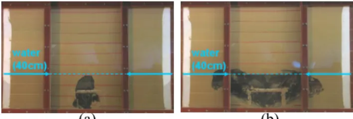
Kuwano et al. (2010)1) and Sato & Kuwano (2008) 2) investigated the mechanism of ground cavity and surrounding loosening due to the failure of sewer pipes. It was found that the state of water infiltration and soil properties are the governing factors for the growth of the ground cavity and loosening, while the failure of pipe is a trigger of the phenomenon. Kuwano et al. (2010)3) further conducted a series of mode tests to examine the pattern of underground cavity formed in Toyoura sand model ground in case that constant subsurface water flow exists, using soil chamber as shown in Figure 11. A cavity expanded laterally, as shown in Figure 12, with time until the ceiling of the cavity lost its stability.
N
Road
The 8th fairway Water hazard Land fill of about 10-15m thick
Reservoir Large amount of soil sediment Collapse ??? Old stream
REIKO KUWANO and YUKIHIRO KOHATA
116 Figure 10. Formation of underground cavity
Figure 11. A soil chamber for cavity formation test
(a) (b)
Figure 12. Process of cavity formation (a: 16 minutes after water table was raised to 40cm, b) 84 minutes after water table was raised to 40cm.
Based on the research, the followings are considered to be key issues for explaining the formation of large underground cavity in this case.
(1) Soil properties
The soil was permeable, subjected to the erosion relatively easily. Fines can be first flown away with water, which created ground loosening around the cavity.
(2) Ground water
There was a subsurface water path which can transport soil out of the hole with water. There is also seasonal change in ground water level, which may accelerate the cavity growth as the saturation of soil at the ceiling helps failure and expansion of the cavity.
(3) Soil loss
Direct trigger of the formation of natural water path may be a defect of drainage pipe. But the state and the current condition of the pipes have not yet examined.
5 SUMMARY
A case of large scale ground collapse in the old fill ground was investigated and described in this paper. The underground cavity appeared to be caused by subsurface erosion deep in the ground and to expand upward till it was eventually caused the catastrophic failure. It should be noted again the importance of proper drainage work in land fill construction.
REFERENCES
1) Kuwano,R., Horii,T., Yamauchi,K. and Kohashi,H. (2010): Formation of subsurface cavity and loosening due to defected sewer pipe, Japanese Geotechnical Journal, Vol.5, No.2, 349-361, (in Japanese).
2) Sato, M. and Kuwano, R. (2008): Experimental Study on the Evaluation of Loose Ground Surrounding a Cavity in Soil,
Proc. 7th International symposium on new technologies for urban safety of mega cities in Asia, USMCA, Beijing, October 2008, 751-758.
3) Kuwano,R., Sato,M. and Sera,R. (2010): Study on the detection of underground cavity and ground loosening for the prevention of ground cave-in accident, Japanese
Geotechnical Journal, Vol.5, No.2, 219-229, (in Japanese).
Original stream Land fill constructed Original stream Land fill constructed
Erosion progressed Cavity and surrounding loosening expand
Failure of cavity ceiling Erosion progressed
Cavity and surrounding loosening expand
Failure of cavity ceiling Formation of small cavity due to erosion
at some point Natural water path is formed
along the old stream
Formation of small cavity due to erosion
at some point Natural water path is formed
along the old stream
By repetition of erosion and failure of cavity ceiling, a cavity moves upward By repetition of erosion and failure of cavity ceiling, a cavity moves upward
5mm wide opening
Soil chamber(2m×0.5m×h1.2m)
Water chamber Toyoura sand