of the Kori-1 Nuclear Power Plant
Seo-Yeon Cho1,*, ByongSup Kim1,Youngsuk Bang2, and KeonYeop Kim2 1SMART Power Co., Ltd., 82, Saemunan-ro, Jongno-gu, Seoul, Republic of Korea
2FNC Technology Co., Ltd., 13, Heungdeok 1-ro, Giheung-gu, Yongin-si, Gyeonggi-do, Republic of Korea
(Received October 28, 2020 / Revised December 21, 2020 / Approved January 17, 2021)
Chemical decontamination of primary systems in a nuclear power plant (NPP) prior to commencing the main decommis-sioning activities is required to reduce radiation exposure during its process. The entire process is repeated until the desired decontamination factor is obtained. To achieve improved decontamination factors over a shorter time with fewer cycles, the appropriate flow characteristics are required. In addition, to prepare an operating procedure that is adaptable to various con-ditions and situations, the transient analysis results would be required for operator action and system impact assessment. In this study, the flow characteristics in the steady-state and transient conditions for the chemical decontamination operations of the Kori-1 NPP were analyzed and compared via the MARS-KS code simulation. Loss of residual heat removal (RHR) and steam generator tube rupture (SGTR) simulations were conducted for the postulated abnormal events. Loss of RHR results showed the reactor coolant system (RCS) temperature increase, which can damage the reactor coolant pump (RCP)s by its cavitation. The SGTR results indicated a void formation in the RCS interior by the decrease in pressurizer (PZR) pressure, which can cause surface exposure and tripping of the RCPs unless proper actions are taken before the required pressure limit is achieved.
*Corresponding Author.
Seo-Yeon Cho, SMART Power Co., Ltd., E-mail: [email protected], Tel: +82-2-731-6100
ORCID
Seo-Yeon Cho http://orcid.org/0000-0002-5299-3652
Youngsuk Bang http://orcid.org/0000-0003-3837-0413 ByongSup Kim KeonYeop Kim http://orcid.org/0000-0002-1604-9330http://orcid.org/0000-0001-6511-2458
Keywords: Kori-1 Nuclear Power Plant, Decommissioning, Chemical decontamination, Flow characteristics, Transient analysis, MARS-KS
1. Introduction
Chemical decontamination for decommissioning NPP is the process of removing oxide films and metal oxide de-posits from the interior surfaces of components and pip-ing. This process is required for all major reactor coolant systems prior to the start of the main decommissioning ac-tivities to reduce the radiation exposure to workers during decommissioning and minimize the radioactive wastes. Ba-sically, the main process can be divided into two groups: 1) dissolving of the oxide films and metal oxides via chemical reactions and 2) removal of the left-over and waste chemi-cals via filtration or ion exchange. The entire process is re-peated until the desired decontamination factor is obtained. Depending on the chemicals to be injected, many different processes have been proposed and applied to components and systems for further operation or decommissioning of plant. As these processes have been conducted many times over previous years, the chemical processes can be ad-vanced to be mature and well-defined. However, it has been noted that the application of these chemical-decontamina-tion processes should be varied according to differing NPP types, system condition with configurations and, chemical reagents etc. [1].
The Kori-1 NPP, a 2-loop pressurized water reactor (PWR), was permanently shut down on June 18, 2017, and it is the first commercial NPP in South Korea entering the decommissioning phase [2]. Methodologies for the decon-tamination of Kori-1 NPP have been studied, and a chemi-cal decontamination system has been developed and tested. In Ref. [3], decontamination technologies are reviewed and key considerations for planning of decontamination are de-scribed. In Ref. [4], chemical and mechanical techniques for primary system decontamination are compared. In Ref. [5], the operational concept of the full system chemical de-contamination for Kori-1 is described based on obtained overseas experiences. In Ref. [6], a numerical analysis is conducted to examine the operation of the RHR system pump for providing the circulating flow rate. A research
project considering the decontamination technology for the reactor coolant system and dismantled equipment is cur-rently under development [7].
To achieve improved decontamination factors over a shorter time with fewer cycles, the appropriate flow char-acteristics should be provided. If the circulating flow rate is low, the dissolved metal elements could settle and be-come deposited, which results in hot spot formation or the plugging of tubes. As noted in Ref. [5-6], operating only the RHR pumps in chemical decontamination may not pro-vide a sufficient flow rate, thus additional operation of the pumps would be required. Especially in Ref. [5], the both the flow velocity and Reynolds number are calculated to investigate the flow characteristics and low flow velocity and Reynolds number are found in steam generator tubes.
Moreover, if the reactor pressure vessel (RPV) and steam generators (SGs) are within the scope of the decon-tamination, operating of RCP is recommended. It has been shown that high flow rates yield improved decontamination results [8]. It is important to note that RCP operation re-quires several other considerations, e.g., system pressuriza-tion and RCP seal injecpressuriza-tion. Therefore, proper procedures should be provided to operators and workers. Transient analysis results would provide a valuable basis for prepar-ing such procedures under various system conditions, in-cluding abnormal situations.
In this study, the flow characteristics of the Kori-1 NPP RCS for chemical decontamination operations is analyzed. In addition, representative transient events are considered for identifying anticipated transients to the system. First, a system model developed by MARS-KS (1.4 version) is prepared. MARS-KS is a computer code based on one-di-mensional two-fluid formulation and widely used for ther-mal hydraulic accident analyses of light water reactors such as Loss of Coolant Accident, Loss of Feedwater, SGTR [9]. Second, for the steady-state analysis, the operational con-ditions (pressure and temperature) and flow characteris-tics (e.g., velocity and Reynolds number) are investigated. Third, the possible initiating events that result in transience
are identified and simulations are conducted. The timing of major events, rate of system condition changes and impacts with respect to the chemical process are examined.
2. Numerical modeling
The Kori-1 NPP is a 587-MWe PWR with 2 loops of Westinghouse-type. The primary systems included in the RCS decontamination are considered to be as follows: RPV, SGs, PZR, RCS piping, RCPs, residual heat removal system (RHRS) and chemical and volume control system (CVCS). The fuel is considered to have been removed and safety injection systems are excluded. It is assumed that the secondary sides of SGs are exposed to the atmosphere (dry conditions). The Kori-1 RCS considered in this study is presented in Fig. 1. Note that the RCS pressure may be
controlled via nitrogen gas injection through the PZR. The temperature and flow rate can be obtained by using the RCPs. The RCS inventory and PZR level are controlled via CVCS letdown and charging. The target conditions for RCS chemical decontamination are shown in Table 1. The minimum operating pressure of RCP is 22 bar from the pre-vious study [10]. Considering a margin, the operation pres-sure is determined as 26.15 bar. The chemical injection and decomposition facility are assumed to be connected to the RHRS return line, as shown in Fig. 2.
The MARS model is developed by modifying a model previously developed for accident analysis [11].
The components with control functions related to safety injections are removed. The parameters and control log-ics for simulating the decontamination process conditions are added. In Fig. 3, the nodalization of the Kori-1 RCS of MARS model is presented. In this study, the steady-state
Process PZR Level[%] RCS Temperature[°C] RCS Pressure[bar]
Oxidation/Dissolution 45 95 26.15
Table 1. RCS conditions
Fig. 1. Schematics of the Kori-1 RCS.
RHR #2 RHR #2 Loop 1 Loop 2 RCP #1 RCP #2 CVCS Letdown CVCS Charging SG #1 SG #2 RHR #1 RHR #1 PZR RX
①
②
③
④
⑥
⑦
⑧
⑨
⑤
Fig. 3. Nodalization of the Kori-1 RCS MARS Model.
Fig. 2. Schematics of the chemical decontamination equipment connections. RHR HX PZR RCS Hot Leg RCS Cold Leg RCP Suction RHR Pump RCS Pump Rx Decon.
and transient RCS conditions are considered. The other sys-tems connected to the RCS, including the CVCS and RHR, are simplified for use as boundary conditions. Malfunctions in those systems are modelled using time-dependent user-specified components.
3. Numerical results and discussion
3.1 Steady-state operations
The flow characteristics under the chemical decontami-nation process conditions shown in Table 1 are analyzed. Two RCPs for loop 1 and loop 2, 1 train of the RHRS for
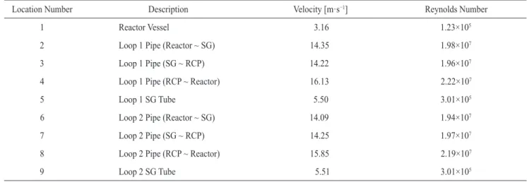
removing heat induced by the RCP, and the CVCS for the RCS inventory control are operated. The flow velocities and Reynolds numbers in various RCS locations are sum-marized in Table 2. The location number is indicated in Fig.
1. As can be seen in Table 2, the Reynolds numbers in the RCS flow are larger than 100,000 in all regions, which indi-cates that a sufficient circulating flow rate in turbulent flow will be provided in the reactor vessel and SG tubes [12]. 3.2 Transient analysis
Transient analyses are conducted for the postulated ab-normal conditions. In order to determine the possible tran-sient events, the initiating events considered in Emergency Operating Procedure (EOP) and Abnormal Operating Pro-cedure (AOP) of Kori-1 and -2 are reviewed.
Most anticipated transient events are evaluated for this study and the events which have similar transient behav-ior are grouped and the representative event is derived. As a result, anticipated as commonly severe cases for system integrity are selected for representative transient analysis cases.
Location Number Description Velocity [m·s−1] Reynolds Number
1 Reactor Vessel 3.16 1.23×10⁵
2 Loop 1 Pipe (Reactor ~ SG) 14.35 1.98×10⁷
3 Loop 1 Pipe (SG ~ RCP) 14.22 1.96×10⁷
4 Loop 1 Pipe (RCP ~ Reactor) 16.13 2.22×10⁷
5 Loop 1 SG Tube 5.50 3.01×10⁵
6 Loop 2 Pipe (Reactor ~ SG) 14.09 1.94×10⁷
7 Loop 2 Pipe (SG ~ RCP) 14.25 1.97×10⁷
8 Loop 2 Pipe (RCP ~ Reactor) 15.85 2.19×10⁷
9 Loop 2 SG Tube 5.51 3.01×10⁵
Table 2. Steady-state flow characteristics in the RCS
Analysis Cases Case Description Plant Condition
RCP CVCS RHR
1
Loss of RHR 2 EA Available Available Disabled
2 2 EA Available Disabled Disabled
3 SGTR 2 EA Available Available Available
As a representative case of a loss of heat removal, the loss of RHR is considered. For the loss of the RCS inven-tory, SGTR is considered. The analysis cases with system operations are summarized in Table 3.
3.2.1 Loss of RHR
The loss of RHR event could be initiated by an RHR pump failure, which results in RHRS isolation. Due to the insufficient removal of heat generated by the RCS opera-tion, the pressure and temperature of the RCS would in-crease. As shown in Fig. 4, the RCS temperature would increase gradually due to the loss of heat removal by the
RHRS. The RCS pressure and the PZR water level would be maintained if the CVCS is in operation to charge and letdown the flow control. Conversely, the RCS pressure and PZR water level would increase rapidly without CVCS op-eration (Fig. 5 and 6). The RCS flow rate remains the same as the steady-state rate because it is assumed that the RCP operates normally, even under transient conditions (Fig. 7). Regarding the decontamination process, there would not be significant degradation of decontamination performance because the circulating flow would be maintained with the RCP operation. However, it is necessary to restore the heat removal by the RHRS because the RCS temperature rise
0 5,000 10,000 15,000 220.00 200.00 180.00 160.00 140.00 120.00 100.00 80.00 Time [s] RCS Temper atur e [℃ ] w/ CVCS w/o CVCS
Fig. 4. RCS hot leg temperature–Loss of RHR.
0 5,000 10,000 15,000 100 90 80 70 60 50 40 30 20 10 0 Time [s] Pr essur iz er L ev el [%] w/ CVCS w/o CVCS Fig. 6. PZR level–Loss of RHR. 0 5,000 10,000 15,000 200 150 100 50 0 Time [s] Pr essur iz er P ressur e [bar] w/ CVCS w/o CVCS Fig. 5. PZR pressure–Loss of RHR. 0 5,000 10,000 15,000 16 14 12 10 8 6 4 2 Time [s] Liquid Velocit y in R CS [m ·s −1] Core
Loop1 Pipe (Hot Leg) Loop1 SG Tube Loop2 Pipe (Hot Leg) Loop2 SG Tube
can cause cavitation, which can damage the RCPs. Accord-ing to the simulation, the RCS temperature would be in-creased by 0.47°C·min−1. Therefore, the RCS temperature would increase to 109°C after 30 min of heat removal. As-suming that the pump cavitation would occur over 200°C, there would be sufficient time for the operators to take proper action, e.g., terminate the RCP operation and decon-tamination process [13].
3.2.2 SGTR
The SGTR event could be initiated by a guillotine break of one SG Tube. As a result of such a tube break, the RCS
coolant would leak into the secondary SG system. There-fore, the RCS pressure and PZR level would decrease rap-idly, as shown in Fig. 8 and Fig. 9. Note that the required minimum RCP inlet pressure is 22 bar. As shown in Fig. 8, the PZR pressure would be decreased below the required pressure after 152 s following the SGTR and the RCPs will be tripped right after the event occurs. Therefore, it is rec-ommended to equip the control logic for automatic diagno-sis and trip the RCPs.
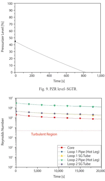
It is important to note that the depletion of the PZR (i.e., 0% pressurizer level) would indicate a void formation or surface exposure in the RCS interior. As shown in Fig. 10
0 50 100 150 200 27 26 25 24 23 22 21 20 Time [s] Pr essur iz er P ressur e [bar] 22 bar at 152s Fig. 8. PZR pressure–SGTR. 0 5,000 10,000 15,000 20,000 16 14 12 10 8 6 4 2 0 -2 Time [s] Liquid Velocit y in R CS [m ·s −1] Fig. 10. RCS velocity–SGTR. 0 200 400 600 800 1,000 100 90 80 70 60 50 40 30 20 10 0 Time [s] Pr essur iz er L ev el [%] Fig. 9. PZR level–SGTR. 0 5,000 10,000 15,000 20,000 107 106 105 104 103 102 101 100 Time [s] Reynolds Number
Fig. 11. Reynolds number–SGTR. Core
Loop 1 Pipe (Hot Leg) Loop 1 SG Tube Loop 2 Pipe (Hot Leg) Loop 2 SG Tube
Core
Loop 1 Pipe (Hot Leg) Loop 1 SG Tube Loop 2 Pipe (Hot Leg) Loop 2 SG Tube
and Fig. 11, the RCS circulating flow would be constantly decreased and turbulent flows would be maintained for 20,000 s. To avoid leakage of RCS coolant via tube break-age, the secondary side pressurization of SG could be con-sidered as well.
4. Conclusions
The flow characteristics of the Kori-1 NPP for the chemical decontamination process were analyzed. A MARS model was developed and the RCS flow conditions at steady-state and transient conditions were investigated. While the RCP operation would provide a sufficient RCS
circulating flow, it would require the heat removal provided by the RHRS, as well as a maintained pressure. The results of this study may be utilized to optimize the decontamina-tion process of this plant and prepare the required opera-tional procedures.
Acknowledgements
This work was supported by the Korea Institute of Energy Technology Evaluation and Planning (KETEP), granted financial resources from the Ministry of Trade, Indus-try & Energy (MOTIE) of the Republic of Korea (No. 20191510301310).
REFERENCES
[1] H. Ocken. Decontamination handbook, The Electric Power Research Institute Report, 57-73, TR-112352 (1999).
[2] World Nuclear Association and IAEA Power Reactor Information System. “Reactor Database in South Ko-rea for permanent shutdown Ko-reactor, Kori 1.” 2016-2021 World Nuclear Association Information Library.
Accessed Sep. 20 2020. Available from: http://www. nuclear.org/reactor/default.aspx/KORI-1.
[3] G.Y. Park and C.L. Kim, “Chemical Decontamination Design for NPP Decommissioning and Considerations on its Methodology”, J. Nucl. Fuel Cycle and Waste Technol., 13(3), 187-199 (2015).
[4] J.S. Song, M.Y. Jung, and S.H. Lee, “A Study on the Applicability for Primary System Decontamination Through Analysis on NPP Decommission Technology
and International Experience”, J. Nucl. Fuel Cycle and Waste Technol., 14(1), 45-55 (2016).
[5] D.H. Lee, H.C. Kwon, and D.K. Kim, “Full System Chemical Decontamination Concept for Kori Unit 1 Decommissioning”, J. Nucl. Fuel Cycle and Waste Technol., 14(3) 289-295 (2016).
[6] H.S. Kim and C.R. Kim, “Flow Characteristics Evalu-ation in Reactor Coolant System for Full System De-contamination of Kori-1 Nuclear Power Plant”, J. Nucl. Fuel Cycle and Waste Technol., 16(3), 389-396 (2016). [7] C. Kim. Chemical Injection & Decomposition Facility,
Korea Hydro & Nuclear Power Technical Report, 4-8, R&D-FSD-CIDF-000 (2018).
[8] T.A. Beaman and J.L. Smee. Evaluation of the Decon-tamination of the Reactor Coolant Systems at Maine Yankee and Connecticut Yankee, Korea Hydro &
Nucle-ar Power Technical Report, 23-71, TR-112092 (1999). [9] B.D. Chung, K.D. Kim, B.S. Won, J.J. Jun, S.W. Lee,
M.K. Hwang, and C. Yoon. MARS Code Manual Vol-ume I: Code Structure, System Models, and Solution Method, Korea Atomic Energy Research Institute Tech-nical Report, 1-20, KAERI/TR-2812/2004 (2004). [10] H. Kim. Development of RCS & Equipment
Decon-tamination Technology for NPP Decommissioning Design, Ministry of Trade, Industry and Energy Final Report, 50, 206 (2018).
[11] M.K. Hwang. Development of the MARS Input Model for Kori Nuclear Units 1 Transient Analyzer, Korea Atomic Energy Research Institute Technical Report, 8-13, KAERI/TR-2847/2004 (2004).