Hydraulic Analysis of a Small Scale Intermediate Heat Exchanger Test Loop
Dong Seok Oh, SeungDeok Hong, WonJae Lee, JongHwa ChangKorea Atomic Energy Research Institute, 150 Duckjin Yusung Daejeon Korea, [email protected]
1. Introduction
The construction work of a small scale intermediate heat exchanger (IHE) test loop has been initiated in the beginning of this year as a series of the high temperature gas reactor project. The loop consists of a primary loop and a secondary loop. The detail description of a loop is shown in reference 1. A primary loop would provide high temperature nitrogen more than the 900 Celsius degree under the 6 MPa pressure condition. The high enthalpy of nitrogen transfers the energy to the sulfur trioxide flowing through the secondary loop at the decomposer and the trioxide sulfur is divided into dioxide sulfur and oxygen. The objective of the loop is to provide the high pressure and temperature environment to development of a high performance decomposer and the performance test of the material is also very challengeable thing. The schematic loop diagram with the conception of equipment has been developed during this year. The pressure loss of the loop is needed as a specification of equipment purchase. In this paper, the pressure loss of a primary loop has been evaluated and a decomposer, a heat exchanger, and an air cooler geometry have been designed prior to hydraulic evaluation.
2. Heat Equipment Sizing
The decomposer, the heat exchanger, and the air cooler needs the capacity more than 10 KW which can be evaluated from the rate of energy stored inside the control volume including equipment. The decomposer and the heat exchanger are designed with identical dimension due to similar thermal capacity and the merit of manufacturing cost and the maintenance. The material of a decomposer will be made by silicon carbide can be endurable sulfur environment. The heat sink is calculated for one dimensional geometry problem with the three layers of a nitrogen channel, a silicon carbide wall, and a trioxide sulfur channel. The channel of 150 mm width, 0.6 mm height, and 650 mm depth with 10 layers is reviled as the proper geometric dimension from the calculation. The nitrogen in primary side flows through 5 layers and the trioxide sulfur paths through lest the 5 layers. The capacity of decomposer is little lower than that of the heat exchanger. The difference of capacity is only due to the inlet and outlet condition discrepancy. If we use the finned channel instead of the pure channel, the thermal capacity will be increased and more compact
decomposers are designed. On the other side the pressure loss will be slightly increased.
The air cooler is designed with finned tube to increase cooling efficiency and also can be reduced pressure loss in the tube by using relative short tube comparing to the bare cooling tube. The air cooler is designed to pass thorough the small diameter finned tube cooled by forced convection from outside the fin with 200 W/m2 K of the heat transfer coefficient. The 20 mm diameter tube with 2 m length is selected as the air cooler tube. The 50 mm fin diameter, 1 mm fin thickness, and 2 mm pin pitch is selected as the fin dimension. The cooling capacity of the air cooler is 16 KW.
3. Pressure Loss Evaluation
The primary loop pressure drop is needed as design input of the compressing recirculator.
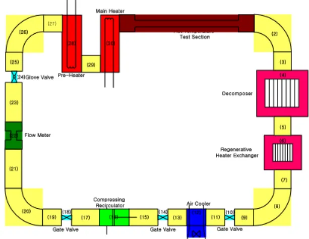
Figure 1. Schematic Diagram of Primary Loop The schematic diagram of primary loop is shown in Figure 1. The pressure loss coefficient is calculated by utilizing the models published in open literature of reference 2. The models used for the calculation are shown in the Table 1. The friction factor is calculated by the Moody chart. The pressure loss of the flow meter is provided by the manufacturer [3].
The pressure loss of each component is shown in Table 2. The total pressure loss of a primary loop is 60 KPa. The pressure loss of a flow meter is more than half of the total pressure loss.
Pre-Heater
Compressing
Recirculator Air Cooler Regenerative Heater Exchanger Decomposer Hot Temperature Test Section (1) (2) (3) (4) (5) (6) (7) (8) (9) (10) (11) (12) (14) (16) (17) (18) (19) (20) (21) Flow Meter (13) (15) (26) Main Heater (22) (23) (24) (25) (27) (28) (29) (30) Glove Valve
Gate Valve Gate Valve Gate Valve
Transactions of the Korean Nuclear Society Autumn Meeting Busan, Korea, October 27-28, 2005
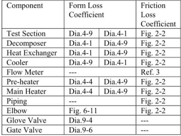
Table 1. Models Utilized for Pressure Loss Coefficient
Component Form Loss Coefficient
Friction Loss Coefficient Test Section Dia.4-9 Dia.4-1 Fig. 2-2 Decomposer Dia.4-1 Dia.4-9 Fig. 2-2 Heat Exchanger Dia.4-1 Dia.4-9 Fig. 2-2
Cooler Dia.4-9 Dia.4-1 Fig. 2-2
Flow Meter --- Ref. 3
Pre-heater Dia.4-4 Dia.4-9 Fig. 2-2 Main Heater Dia.4-4 Dia.4-9 Fig. 2-2
Piping --- Fig. 2-2
Elbow Fig. 6-11 Fig. 2-2
Glove Valve Dia.9-4 ---
Gate Valve Dia.9-6 ---
Table 2. Pressure Loss for Each Component
Component Form Loss
[Pa] Friction Loss [Pa] Test Section 2444 3960 10380 Decomposer 84 45 3193 Heat Exchanger 84 45 2406 Cooler 35 31 322 Flow Meter 35000 0 Pre-heater 107 42 0.2 Main Heater 211 278 0.3 Piping 0 455 Elbow 623 10 Glove Valve 635 0 Gate Valve 394 0 Total 43889 16766.5
The friction loss of the test section is the highest number in frictional pressure loss. The frictional pressure loss of the decomposer and the heat exchanger also highly influence on the frictional pressure loss. The loop pressure loss of 100 KPa is recommended as a design value of the loop in consideration of the uncertainty and the design flexibility.
4. Concluding Summary
The geometric parameters of the decomposer, the heat exchanger, and the air cooler with more than 10 KW thermal capacity have been proposed and pressure loss of the primary loop has been evaluated by utilizing the pressure loss models published in open literature. The results are summarized as follows;
1) The decomposer and the heat exchanger is plate type with 5 layers for each fluid. The finned channel instead of
the pure channel will allow more compact design. On the other side these pressure loss will be slightly increased.
2) The finned air cooler is designed to increase thermal capacity as well as to reduce pressure loss of the air cooler.
3) The total pressure loss of the primary loop is estimated as 60 KPa. The pressure loss of the flow meter is more than half of the total pressure loss. The loop pressure loss of 100 KPa is recommended as a design value of the loop in consideration of the uncertainty and the design flexibility.
4) The more detail analysis for design optimization with CFD code on thermal equipments including the non uniform flow distribution influence is needed.
REFERENCES