Conceptual Design of Fuel Storage and Handling System for Integral Reactor
JaeSeon Lee, JongIn Kim, MinHwan Kim, JeYong Yu, DongOk Kim, Suhn Choi, KeungKoo Kim Korea Atomic Energy Research Institute, Mechanical Engineering Division, 305-600, P.O. Box 105, Yuseong,Daejeon, Korea, [email protected] 1. Introduction
Fuel storage and handling system means the integral system including relevant equipment, tools and corresponding processes from reception of fresh fuel channels to shipping out of spent fuel channels within spent fuel shipping cask from the plant. Fuel storage and handling system consists of fresh fuel storage and handling system, spent fuel storage and handling system, reactor refueling system, and fuel transfer mechanism.
In commercial nuclear power plant with loop type reactor, spent fuel channels are extracted from the reactor core in the refueling pool and delivered to the spent fuel storage rack through fuel transfer mechanism in the water.
Fresh fuel channels are transferred from the composite building to the reactor for refueling via fuel transfer mechanism. All the processes are accomplished in the water pools and water canals. Fresh fuel channels are stored and inspected in the air before refueling. To handle the fuel channels in the water, there are refueling pool in the reactor building, fuel transfer mechanism between the reactor building and the compound building, and refueling canals and storage pool in the compound building.
Recently small-to-medium size multi-purpose advanced reactor draws major attention because of its space advantages, adaptive nature, diversity of application, simplicity of reactor system, and passive safety approach. The fuel storage and handling system for this integral reactor also needs to be developed to enlarge its merits and to increase nuclear safety. The design concepts of fuel storage and handling system for the integral reactor are presented in this paper.
2. Design characteristic of fuel storage and handling system for integral reactor
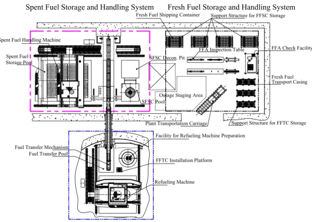
2.1 Fresh Fuel Storage and Handling System
Fresh fuel channels are delivered to the plant from the manufacturer with the fresh fuel shipping containers and stored in the support structure. Fresh fuel channels are inspected at the inspection table and the check facility before refueling, and stored in the fresh fuel transport casings. They are transferred on the plant transportation carriage to the reactor building through the equipment hatch and installed on the FFTC installation platform. Fresh fuel channels are handled and transferred in the air [1].
2.2 Reactor Refueling System
The upper structures of the reactor including the pressurizer are removed with the reactor servicing equipments for refueling after reactor shutdown and cooling. A refueling insulation tank is introduced instead of refueling pool. It is installed on the reactor and filled with refueling water to reduce irradiation to worker and fuel channel cooling [2, 3]. The refueling machine extracts spent fuel channel from the reactor core or inserts fresh fuel channel into the core. Refueling tube with gripper gets down on the reactor core, and grips the fuel head and extracts the fuel channel. Refueling tube with spent fuel channel gets up into the refueling cask and the gate valve is closed for transporting. Water is captured in the refueling cask and it works as coolant and insulator.
When it extracts spent fuel channel, it moves to the position of fuel transfer mechanism seat along the refueling machine carriage rail and bridge rail. There is auxiliary water tank on the refueling machine to supply additional water when cooling water in the refueling cask dries out in case of emergency.
To install fresh fuel channel in the reactor core, the refueling machine grips and extracts fresh fuel channel from the fresh fuel transport casing and moves to the designated reactor core coordinate and installs fresh fuel channel in the reactor core.
After refueling, refueling insulation tank is removed and stored at facility for refueling machine preparation. The refueling machine is checked and repaired at this facility.
2.3 Fuel Transfer Mechanism
Spent fuel channel which is extracted from the reactor core are transferred to the composite building via the fuel transfer mechanism.
Spent fuel channel is inserted in the fuel transfer mechanism carriage seat at the reactor building side vertically and the seat rotates to the horizontal position. Spent fuel is transferred through the guide tube to the composite building and rotated to the vertical position. The fuel transfer mechanism carriage seat is installed on the fuel transfer mechanism carriage and the carriage is driven by the wiring rope system.
The guide tube of fuel transfer mechanism connects fuel transfer pool in the reactor building and the fuel transfer canal in the composite building. Blind flange and fuel transfer mechanism gate valve are to seal the both ends of the guide tube [4].
Transactions of the Korean Nuclear Society Autumn Meeting Busan, Korea, October 27-28, 2005
2.4 Spent Fuel Storage and Handling System
Spent fuel channels are extracted from the fuel transfer mechanism carriage seat by the spent fuel handling machine and inspected at the spent fuel channel cladding leaktightness control equipment seat. They are stored in the spent fuel storage rack in the spent fuel storage pool [5]. Stored spent fuel channels are loaded in the spent fuel shipping cask for taking out of plant in the spent fuel shipping cask pool.
3. Conclusions
Conceptual design results of fuel storage and handling system for the integral reactor are introduced. Each subsystem and its equipment has its own design characteristics and unique design features. A detail design can be produced based on this conceptual design. 4. Acknowledgement
This work has been performed under the nuclear research and development program sponsored by the Ministry of Science and Technology, Korea.
REFERENCES
[1] M.H. Kim, etc., Conceptual Design of New Fuel Storage and Handling Subsystem for the Integral reactor, 2005 Korean Nuclear Society Spring Meeting, 2005
[2] J.S. Lee, J.I. Kim, M.H. Kim, J.Y. Yu, D.O. Kim, and K.K. Kim, Reactor refueling system conceptual design, 2004 Korean Nuclear Society Autumn Meeting, p. 1365, 2004
[3] J.S. Lee, etc., Reactor Refueling System Conceptual Design for Integral Reactor, 2005 Korean Nuclear Society Spring Meeting, 2005
[4] S.H. Lee, etc., Design Features of Fuel Transfer Mechanism for SMART-P, 2005 Korean Nuclear Society Spring Meeting, 2005
[5] J.Y. Yu, etc., Conceptual Design of Spent Fuel Storage and Handling for SMART-P Plant, 2005 Korean Nuclear Society Spring Meeting, 2005
Transport Casing
Spent Fuel Storage and Handling System Fresh Fuel Storage and Handling System
Reactor Refueling and Fuel Transfer Mechanism
7
000
Spent Fuel Handling Machine
Fuel Transfer Mechanism
Facility for Refueling Machine Preparation
Refueling Machine SFSC Pool SFSC Decon. Pit FFTC Installation Platform Spent Fuel Storage Pool
Fuel Transfer Pool
Plant Transportation Carriage
Support Structure for FFSC Storage Fresh Fuel Shipping Container
FFA Inspection Table FFA Check Facility
Support Structure for FFTC Storage Fresh Fuel Outage Staging Area