Journal of International Conference on Electrical Machines and Systems Vol. 3, No. 4, pp. 398~402, 2014 398
Permanent Magnet Eddy Current Analysis of SPM Synchronous
Motors according to Magnet Shapes
Sun-Kwon Lee *, Gyu-Hong Kang *, Byoung-Woo Kim **, and Jin Hur **
Abstract
– This paper presents the comparison study of permanent magnet (PM) eddycurrent of concentrated winding type surface permanent magnet synchronous motor (SPMSM) with different rare-earth magnet shapes. The fractional slot winding having 10 poles and 12 slots is studied. The PM eddy current is analyzed to compare for each shape by 2 dimensional (2D) finite element analysis (FEA). The eddy current and their loss of particular position of PM as well as their distributions are displayed for each model. The effect of partly enlarged air-gap made by PM shape to PM eddy current is compared.
Keywords:
SPMSM, Permanent magnet, Eddy current, Finite element analysis1. Introduction
Permanent magnet (PM) machines with a fractional number of slots per pole and a concentrated winding have shorter end windings and lower overall length and yet have high efficiency, torque, and power density [1], [2]. In addition, not only copper loss but also copper cost can be downsized. On the other hand, the eddy current loss in the permanent magnet (PM) increases due to harmonic magnetic fields made by fractional slot pitch condition with concentrated winding [3], [4]. The torque developed by the interaction of higher order space harmonic magneto motive force (MMF) with the field of the permanent magnet. The lower and higher order space harmonics rotating different speeds to that of the rotor magnets can induce high eddy current in the magnet [5]. The electric conductivity of sintered Nd-Fe-B magnet is very high, so the eddy current in PM is high. The temperature rise in PM especially partial area by eddy current loss can cause the partial demagnetization problem.
Some studies deal the eddy current loss analysis and reduction of PM with segmented magnet. Yamazaki investigated the loss-reduction effects by the magnet segmentation in the in the interior permanent magnet (IPM) and surface permanent magnet (SPM) motors with concentrated windings in order to understand the appropriate segmentation method for each motor [3], [4]. The eddy current loss of PM for brushless AC machines is
calculated by analytical methods, and characteristics of magnet position are also discussed [5]. Seo and their colleagues introduced the loss characteristics of IPMSM using adaptive loss coefficients [6]. Yamazaki [7] investigated the PM eddy current loss variation according to stator and rotor shapes, but they are focused on PM types such as IPM, inset, and SPM. Coupled 2-D and 3-D eddy loss analysis of PM in surface PM motors is introduced [8]. The uniform equivalent gap is improved to a variable equivalent gap in space to take account of the space variation of the gap between the PM and the stator core [8]. Design approach to reduce harmonic eddy current losses in the stator. Teeth of IPM is studied considering flux weakening [9], but they did not consider PM eddy current loss. Huang and colleagues [10] introduced the core loss model for PM motor in which flux variation loci in different parts of the motor are predicted by FE transient analysis.
In this paper, we investigated the PM eddy current effects of SPMSM with concentrated winding and fractional pole-slot combination by 2D FEA using Maxwell. The PM eddy current and their relationship to magnetic field characteristics are compared according to PM shape difference. The eddy current loss and magnetic field in particular PM positions are also studied. The study focuses on the eddy current reduction effects of PM in SPMSM by changing air-gap flux distribution with different magnet shapes.
2. Analysis Model Descriptions
Fig. 1 shows the magnetic circuit structure of analyzed
* Korea Marine Equipment Research Institute (sunkonlee
@komeri.re.kr, [email protected])
** School of Electrical Engineering, University of Ulsan, Korea. ([email protected], [email protected])
models. The identical stator with 12 slots concentrated windings is employed for each model, so the only difference between two models is the shape of PM. The center of outer diameter of model1 is same as inner diameter, but model2 has different center which make unequal air-gap length. The detail descriptions of analyzed models are listed in Table 1. The sintered Ne-Fe-B magnets are adopted and their electric conductivity is 625,000 (S/m).
(a) Model1 (b) Model2 Fig. 1. Analysis models with different magnet shapes. Table 1. Specifications of analyzed models
Items Values Unit
Poles-slots 10 poles-12 slots -
Rotational speed 4000 rpm
Armature current 10 A
Stator Out Diameter 180 mm
Stack Length 54 mm
Residual Induction 1.21 T
Magnet Type Nd-Fe-B -
Conductivity of
magnet 625,000 S/m
3.
PM Eddy Current Analysis
In magnetic field analysis, the fundamental equations [11] are given by t A J A v ) 0 ( (1) 0 t A (2)
where, A is magnetic vector potential, Φ is electric scalar potential, J0 is the magnetizing current density, and v and σ
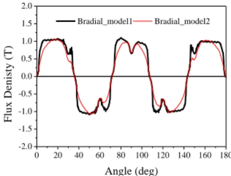
are the magnetic and electric conductivity, respectively. Fig. 2 shows the analyzed results of air-gap flux density distributions for each model. The space harmonics of air-gap flux density of model2 is lower than that of model1 as in the Fig. 3. Space harmonics of air-gap flux can cause the flux variation in PM that results the eddy current increase in PM. 0 20 40 60 80 100 120 140 160 180 -2.0 -1.5 -1.0 -0.5 0.0 0.5 1.0 1.5 2.0 F lu x D e n is ty ( T ) Angle (deg) Bradial_model1 Bradial_model2
Fig. 2. Radial air-gap flux density distribution at open-circuit. 0.00 0.05 0.10 0.15 0.0 0.2 0.4 0.6 0.8 1.0 F lu x D e n si ty ( T ) Frequency Model1 Model2
Fig. 3. Space harmonics of air-gap flux density distribution at open circuit.
(a) Model1 (b) Model2
Fig. 4. Magnetic field and eddy current loss in PM for each model.
Fig. 4 presents the magnetic field, eddy current and loss distributions analysis results for each model with armature current 10A at 0 degree current phase angle in the PM at the same rotation position.
The speed condition for calculation is 4000rpm. The eddy current and loss increase near air-gap due to harmonics of air-gap flux density. In that position of rotation condition (time=15ms), the eddy current loss is maximized at the top of the magnet edge of middle of the
PM which is the narrowest air-gap length position. The eddy current loss of PM is varied with rotating angle due to air-gap harmonics variations. Fig. 5 shows the eddy current loss distributions of single PM in model2 according to time step which describes the rotation angle change at 10A, 0 degree with maximum torque per ampere (MTPA) condition, and 4000rpm. The eddy current loss level is high on the surface of PM which locates in near to air-gap due to the space harmonic of air-gap flux density. The heat source generated by eddy current in PM distributed highly at the magnet surface. The temperature rise in PM can cause the partial irreversible demagnetization, so reduction of eddy current in PM is very important design consideration. The reduction of space harmonics of air-gap flux density by unequal air-gap length produced by PM shape can decrease the eddy current loss and loss density to overall PM area.
Fig. 5. Eddy current loss distribution in PM of model2 according to time step
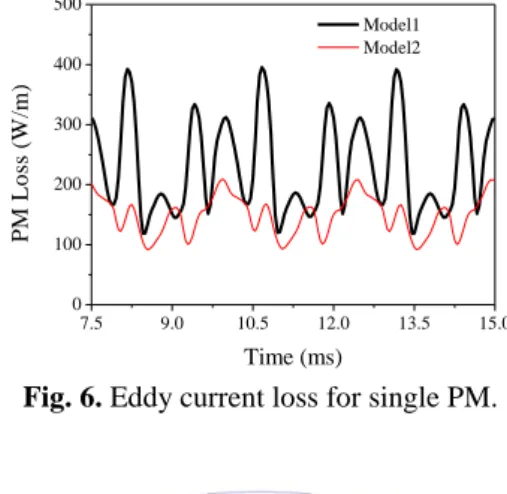
Fig. 6 shows the eddy current loss for single PM with respect to rotation time step at rated condition with 10A, 0 degree and 4000rpm. The average eddy current loss of Model1 is higher than that of Model2 due to harmonic reduction of air-gap flux density by unequal air-gap length with PM shape. The total eddy current loss in PM can be calculated by the sum of the eddy current loss of single PM considering phase shift.
This paper also studies the time variations of field properties including magnetic flux density, PM eddy current and eddy current loss of PM at particular points. Fig. 7 presents the definitions of three positions in PM to calculate the magnetic field and eddy current. The point M1 is the center point of magnet near air-gap. This is located at the narrowest air-gap length position. Points L2 and R2 are left and right side respectively which are partly enlarged air-gap region.
Point L2 is demagnetized region by armature reaction field whereas point R2 is magnetized region. As in Fig. 8, the flux density of R2 is higher than that of L2 due to armature reaction effect. The magnetic flux density for each position in PM varies with respect to rotation, so the eddy current induced. Magnetic flux density of point L2 and R2
of model2 is relatively low compare to that of model1 due to partly enlarged air-gap, so the eddy current loss can be reduced as in Fig. 6.
Fig. 8 shows the eddy current density variations of each position at PM. The eddy current loss at point M1 is highest due to directly affected air-gap flux density harmonics. The flux density variation of point M1 according to rotation higher than that of L2 and R2 as in Fig. 8, so the induced current in PM is relatively high. Fig. 9 presents the PM eddy current density at each position for analyzed model. The eddy current at maximum flux density variation time is very high of which current direction is –z-axis.
7.5 9.0 10.5 12.0 13.5 15.0 0 100 200 300 400 500 P M L o ss ( W /m ) Time (ms) Model1 Model2
Fig. 6. Eddy current loss for single PM.
Fig. 7. Definitions of 3-points for field calculation of PM.
7.5 9.0 10.5 12.0 13.5 15.0 0.50 0.75 1.00 1.25 1.50 F lu x D e n si ty ( T ) Time [ms] Model1_M1 Model1_L2 Model1_R2 7.5 9.0 10.5 12.0 13.5 15.0 0.50 0.75 1.00 1.25 1.50 F lu x D e n si ty ( T ) Time [ms] Model2_M1 Model2_L2 Model2_R2
(a) Model1 (b) Model2. Fig. 8. Flux density variation of each defined position of
PM according to rotation time step.
7.5 9.0 10.5 12.0 13.5 15.0 -4x10⁶ -3x10⁶ -2x10⁶ -1x10⁶ 0 1x10⁶ 2x10⁶ 3x10⁶ 4x10⁶ 5x10⁶ J (A /m ^ 2 ) Time [ms] Model1_M1 Model1_L2 Model1_R2 7.5 9.0 10.5 12.0 13.5 15.0 -4x10⁶ -3x10⁶ -2x10⁶ -1x10⁶ 0 1x10⁶ 2x10⁶ 3x10⁶ 4x10⁶ 5x10⁶ J (A /m ^ 2 ) Time [ms] Model2_M1 Model2_L2 Model2_R2
(a) Model1 (b) Model2. Fig. 9. Eddy current variations of each defined position of
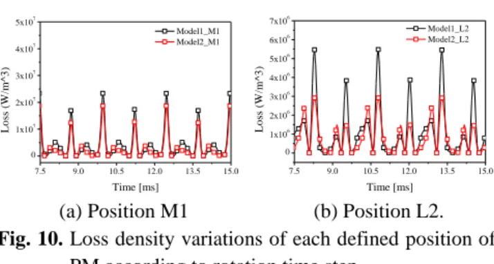
Fig 10 shows the eddy current loss density at each point of PM. The loss density at M1 of model1 is slightly higher than that of model2. In case of position L2, the eddy current loss of model1 is significantly higher than that of model2 in spite of the L2 of model1 do not locate at the surface of PM due to flux density level by air-gap length difference.
Fig. 11 shows the prototype and back EMF measuring result. The prototype of model2 is made and tested. The back EMF analysis results well agree with measured data, so the analysis results can be assumed reliable. The no load loss calculation and measurement results are displayed in Fig. 11, (c). 7.5 9.0 10.5 12.0 13.5 15.0 0 1x10⁷ 2x10⁷ 3x10⁷ 4x10⁷ 5x10⁷ L o ss ( W /m ^ 3 ) Time [ms] Model1_M1 Model2_M1 7.5 9.0 10.5 12.0 13.5 15.0 0 1x10⁶ 2x10⁶ 3x10⁶ 4x10⁶ 5x10⁶ 6x10⁶ 7x10⁶ L o ss ( W /m ^ 3 ) Time [ms] Model1_L2 Model2_L2
(a) Position M1 (b) Position L2. Fig. 10. Loss density variations of each defined position of
PM according to rotation time step.
(a) prototype test set up
0.0 1.5 3.0 4.5 6.0 7.5 -200 -150 -100 -50 0 50 100 150 200 B a c k E M F ( V ) Time (ms) Model1 Model2
(b) back emf comparison,
500rpm 1000rpm 1500rpm Core loss 3.19 13.77 28.48 Magnet loss 0.96 3.74 8.25 Total 4.15 17.51 36.73 6.28 20.1 42.4 Analysis Items Measurement
(c) no load loss comparison
Fig. 11. Prototype of Model2 and back EMF comparison.
5. Conclusion
The permanent magnet eddy current effect of SPMSM with concentrated winding having fractional-slot winding which is 10 pole-12 slot is investigated using 2D FEA. The comparison study according to magnet shapes which modify the space harmonics of air-gap flux density. The eddy current loss distribution of two models is investigated and compared. The eddy current loss near air-gap is much higher than that of other region. The eddy current loss of model2 is reduced by decreasing the harmonics of air-gap flux density by modifying the magnet shape. The PM eddy current effect at particular position is studied by calculating magnetic field properties including magnetic flux density, eddy current and eddy current loss.
References
[1] S. K. Lee, G. H. Kang, and J. Hur, “Finite element computation of magnetic vibration sources in 100kW two fractional-slot interior permanent magnet machines for ship”, IEEE Trans. Magn., vol. 48, no. 2, pp. 867-870, 2012. [2] Z. Q. Zhu, D. Ishak, D. Howe, and J, Chen, “Unbalanced
magnetic forces in permanent-magnet brushless machines with diametrically asymmetric phase windings”, IEEE Trans. Ind. Appl., vol. 43, no. 6, pp. 1544-1553, 2007.
[3] K. Yamazaki, and Y. Fukushima, “Effect of eddy-current loss reduction by magnet segmentation in synchronous motors with concentrated winding”, IEEE Trans. Ind. Appl., vol. 47, no. 2, pp. 779-788, 2011.
[4] K. Yamazaki, M, Shina, Y, Kanou, M, Miwa, and J, Hagiwara, “Effect of eddy current loss reduction by segmentation of magnets in synchronous motors : difference between interior and surface types”, IEEE Trans. Magn., vol. 45, no. 10, pp. 4756-4759, 2009.
[5] J. Wang, K. Atallah, R. Chin, W. M. Arshad, and H. Lendenmann, “Rotor eddy-current loss in permanent-magnet brushless AC machines”, IEEE Trans. Magn., vol. 46, no. 7, pp. 2701-2707, 2010.
[6] J. H. Seo, D. K. Woo, T. K. Chung, and H. K. Jung, “A study on loss characteristics of IPMSM for FCEV considering the rotating field”, IEEE Trans. Magn., vol. 46, no. 8, pp. 3213-3216, 2010.
[7] K. Yamazaki, and Y. Fukushima, and M. Sato, “Loss analysis of permanent-magnet motors with concentrated windings-variation of magnet eddy-current loss due to stator
and rotor shapes”, IEEE Trans. Ind. Appl., vol. 45, no. 4, pp. 1334-1342, 2009.
[8] T. Okitsu, D. Matsuhashi, Y. Gao, and K. Muramatsu, “Coupled 2-D and 3-D eddy current analyses for evaluating eddy current loss of a permanent magnet in surface PM motors”, IEEE Trans. Magn., vol. 48, no. 11, pp. 3100-3103, 2012.
[9] S. H. Han, W. L. Soong, T. M. Jahns, M. K. Guven, and M. S. Illindala, “Reducing harmonic eddy-current losses in the stator teeth of interior permanent magnet synchronous machines during flux weakening”, IEEE Tran. Eng. Convs., vol. 25, no. 2, pp. 441-449, 2010.
[10] Y. Kuang, J. Dong, J. Zhu, and Y. Guo, “Core loss modeling for permanent-magnet motor based on flux variation locus and finite-element method”, IEEE. Magn., vol. 48, no. 2, pp1023-1026, 2012.
[11] L. Ye, D. Li, Y, Ma, and B. Jiao, “Design and performance of a water-cooled permanent magnet retarder for heavy vehicles”, IEEE Trans. Eng. Convs., vol. 26, no. 3, pp. 953-958, 2011.
Sun-Kwon Lee received the B.S. and M.S degree in electrical engineering from Changwon National University, Changwon, Korea, in 1999 and 2001 respectively. From 2001 to 2010, he was employed by LG Electronics Co., Ltd. as a Chief Research Engineer. Since 2010, he has been leader of electric and elelctronic team in Korea Marine Equipment Research Institure. His present research interests include design of high-performance electrical machines, modeling, new concept actuator for special purpose and numerical analysis of electromagnetic fields.
Gyu-Hong Kang was born in Korea on Nov. 5, 1967. He received the B.S. degree in electrical engineering from Changwon National University, Changwon, Korea, in 1992, and M.S. and Ph.D. degrees in electrical engineering from Changwon National University, Changwon, Korea, in 1994 and 2001 respectively. From 1994 to 1998, he was employed by LG Electronics Co., Ltd. as a Senior Research Engineer. From 2001 to 2004, he was employed by Research Professor for BK21 projects with the Department of Electrical Engineering, Changwon National University. From 2005 to 2006, he was employed by Motor-Net Internation Co., Ltd. as a Chief Technical Officer.Senior Research Engineer. From 2007 until 2009, he was a Chief Technical Officer with the GEM-Tech Co., Ltd. Since 2010, he has been a leader of electric and elelctronic team in Korea Marine Equipment Research Institure. His present research interests include design of high-performance electrical machines, modeling, new concept actuator for special purpose and numerical analysis of electromagnetic fields.
Dr. Kang is working as a reviewer for IEEE Transactions on Energy Conversion and Industrial Electronics.
Byeong-Woo Kim received the B.S. and the M.S. degrees in mechanical engineering from Hanyang University, Seoul, Korea, in 1987 and 1990, respectively and the Ph.D. degree from in precision mechanical engineering from Hanyang University, Seoul, Korea, in 2002. From 1989 to 1990, he has been an Inviting Researcher at Precision Measurement Group, Japan Kosaka Research Institute (JKRI), Saitama, Japan. From 1990 to 1994, he has been a Junior Researcher at Sensor Development Group, CAS Cooperation, Seoul, Korea. From 1994 to 2006, he has been a Principal Researcher at Electrical & Electronics Group, Korea Automotive Technology Institute (KATECH), Chunan, Korea. From 2006 Dr. Kim joins at School of Electrical, Electronics & Information Systems Engineering, Ulsan University, Ulsan, Korea, as an Associate Professor. His research interests include electrical and electronics system for automotive applications, control systems for hybrid, fuel cell and electric vehicle systems.
Jin Hur received his Ph.D. in Electrical Engineering from Hanyang University, Seoul, Korea, in 1999. From 1999 to 2000, he was with the Department of Electric Engineering, Texas A&M University, College Station, TX, as a Postdoctoral Research Associate. From 2000 to 2001, he was a Research Professor of Electrical Engineering for BK21 projects at Hanyang University. From 2002 to 2007, he was a Director of Intelligent Mechatronics Research Center, Korea Electronics Technology Institute (KETI), Puchon, Korea, where he worked on the development of special electric machines and systems. Since 2008, he has been an Associate Professor, School of Electric Engineering, University of Ulsan, Ulsan, Korea. He is the author of over 140 publications on electric machine design, analysis and control, and power electronics. He has 1 granted pending US patent and 20 granted pending Korean patents. His current research interests include high-performance electrical machines, modeling, drives, new concept actuators for special purposes and numerical analysis of electromagnetic fields.