Insulation Performance of a Tube-in-tube Modular Feedwater Line for an In-vessel
Once-Through Steam Generator
Jae-Kwang Seo, Han-Ok Kang, Young-In Kim, Juhyeon-Yoon, Sung-Qunn Zee
Korea Atomic Energy Research Institute, Deokjin-dong 150, Yusung-Gu, Daejon
1. Introduction
Steam generator cassette (SGC) of an integral type reactor is a once-through modular type and installed inside the reactor vessel. Modular feedwater line (MFL) penetrates the upper part of the reactor vessel side wall and is connected to the bottom head of the SGC. Due to the design characteristics of the MFL layout, the MFL is exposed to a high-temperature primary coolant during a normal operation. At low flow conditions, in conjunction with other thermal-hydraulic conditions, the feedwater in the MFL can be heated up to near a condition where the feedwater flow becomes unstable. This type of instability is known as the so-called Ledinegg instability. The Ledinegg instability results from the pressure drop-versus-flow response. To prevent the flow instability in the SGC at a low flow condition, it is recommended that the subcooled margin of the feedwater at the modular feedwater header of the SGC is above 20 ℃[1]. In this paper, a thermal insulation design for the MFL and the performance of the insulation with the feedwater flowrate for the given operation conditions of the primary and secondary condition are discussed. A mathematical model of the MFL with a tube-in-tube type insulator has been developed. The recommended type of the thermal insulation of the MFL and the recommended operation conditions for the SGC are discussed.
2. Mathematical Models
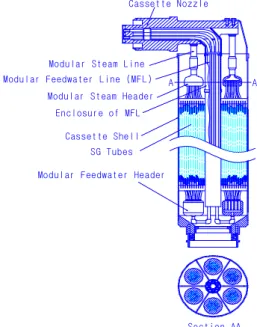
The SGC of interest is shown in Figure 1. One SGC has six MFLs. The six MFLs are enclosed with the enclosure of the MFL. The enclosure of the MFL functions as a first thermal barrier against the heat transfer from the hot side of the reactor coolant to the cold side of the feedwater. The enclosure of the MFL is nearly totally sealed along the length of the MFL except for the bottom portion of the SGC. Each MFL is proposed to be a tube-in-tube type as shown in Figure 2. The water gap between the inner pipe and outer pipe of the tube-in-tube MFL functions as a second thermal barrier. The water in water gap is nearly stagnant and therefore it is expected to provide a good thermal resistance.
To check the combined performance of the first and the second thermal barrier of the proposed tube-in-tube MFL in the enclosure for various operational conditions, mathematical models for such configurations of interest are developed. In a single phase liquid flow, the pressure drop in tube can be assumed to be negligible.
A A
Modular Feedwater Header SG Tubes Modular Feedwater Line (MFL)
Cassette Shell
Cassette Nozzle
Section AA Modular Steam Line
Modular Steam Header Enclosure of MFL
Figure 1 The SGC with sectional view
Inner Pipe of MFL
Outer Pipe of MFL
Enclosure of MFL
Figure 2 Enclosure of the MFL
2.1 Heat Balance Equations
In general, a heat balance equation for N tube-in-tubes in the enclosure can be written as:
LMTD LMTD T A U Q T A U Q dH m Q N Q d dH m Q d 56 . 4 5 56 5 5 . 14 1 14 1 5 5 1 5 1 1 1 ) ( ∆ = ∆ = = − = & & & & & & &
where subscript 4.5 means the midpoint between the outer pipe of the MFL and the enclosure, H is the enthalpy, m& is the mass flowrate. The meaning of the number in the subscript is shown in Figure 2. Overall heat transfer coefficients are defined as follows:
6 6 5 5 6 5 5 ln 5 . 0 1 1 h D D D D k D h U + + = 56
Transactions of the Korean Nuclear Society Autumn Meeting Busan, Korea, October 27-28, 2005
4 4 1 3 4 1 2 3 1 1 2 1 1 ln 5 . 0 ln 5 . 0 ln 5 . 0 1 1 h D D D D k D D D k D D D k D h U eff + + + + = 14
where keff means the effective thermal conductivity of
the water gap in the tube-in-tube.
2.2 Heat Transfer Coefficient Correlations
Empirical correlations used in this study for the heat transfer coefficients for various regions are summarized in Table 1. Wall temperature superheat is considered in the inner side of the tube-in-tube. Heat transfer mechanism for the gap of the tube-in-tube is essentially a natural convection and therefore modeled as an effective conduction. There is a bypass flow in the enclosure area and therefore it may be modeled as a forced, mixed, or natural convection, depending on the flow conditions.
Table 1 Empirical correlations for heat transfer coefficients
Correlations Tube inside Tube-in-tube Enclosure Forced convection SKBK[2] SKBK[2] Mixed & natural
convection Kutateladze[3] Kutateladze[3] Effective conduction for tube-in-tube Kutateladze[3] Partial subcooled nucleate boiling Rohsenow[4] Fully developed
subcooled nuc. boiling
Bergles & Rohsenow[5] Onset of nucleate boiling Bergles & Rohsenow[5] 3. Results
Based on the heat transfer models developed in this study, calculations have been conducted to predict the subcooled margin at the modular feedwater header of the SGC. Representative boundary conditions and results are shown in Table 2. Bypass flow through the enclosure is assumed to be 0.1% of the nominal flow of a reactor coolant.
Table 2 Summary of boundary conditions and results
Operation mode FW flow % SG inlet temp., ℃ FW inlet temp., ℃ Steam pr., MPa FW temp. at header, ℃ Subcooled at header, ℃ 100 310 50 3.55 60.83 182.52 Normal 20 310 50 3.55 97.09 146.26 5 310 50 3.55 177.81 65.54 Startup 5 310 50 1.6 178.31 23.07 5 210 50 1.6 120.61 80.77 2.5 210 50 0.8 150.57 19.84 Heatup 2.5 180 50 0.8 128.93 41.48 3 310 150 4.55 250.92 7.17 PRHRS 2 230 150 2.0 205.15 7.23
From the results of the extensive sensitivity analysis for the effect of the parameters change, it was revealed that the feedwater temperature along the MFW tube is sensitive to the feedwater flow, steam pressure, and primary temperature as shown in Table 2. Bypass flow in the enclosure is also a strong contributor to the feedwater heating. From the results of Table 2, with the
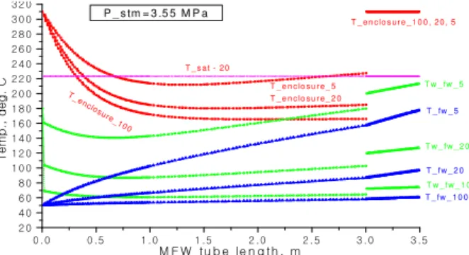
configuration of the tube-in-tube in the enclosure, a sufficient subcooled margin at the MFW header is assured at the given boundary conditions of the operation mode except the PRHRS mode. For the PRHRS mode with the given boundary conditions, the calculation results may be acceptable because it is accidental situations. Figures 3 & 4 show the temperature profiles along the tube length. From the comparison, the effect of the subcooled nucleating boiling is not significant.
0 .0 0 .5 1 .0 1 .5 2 .0 2 .5 3 .0 3 .5 2 0 4 0 6 0 8 0 1 0 0 1 2 0 1 4 0 1 6 0 1 8 0 2 0 0 2 2 0 2 4 0 2 6 0 2 8 0 3 0 0 3 2 0 T _ s a t - 2 0 T _ e n c lo s u r e _ 5 T _ e n c lo s u r e _ 2 0 T _en closu re_10 0 T _ e n c lo s u r e _ 1 0 0 , 2 0 , 5 T w _ fw _ 5 T w _ f w _ 2 0 T w _ f w _ 1 0 0 T _ fw _ 5 T _ f w _ 2 0 T e m p ., d e g . C M F W tu b e le n g th , m T _ fw _ 1 0 0 P _ s tm = 3 .5 5 M P a
Figure 3 Temp. profiles along the tube length at 3.55 MPa
0 . 0 0 . 5 1 . 0 1 . 5 2 .0 2 .5 3 .0 3 .5 2 0 4 0 6 0 8 0 1 0 0 1 2 0 1 4 0 1 6 0 1 8 0 2 0 0 2 2 0 2 4 0 2 6 0 2 8 0 3 0 0 3 2 0 T _ s a t - 2 0 T _ e n c lo s u r e _ 5 T _ e n c lo s u r e _ 2 0 T _ e n c lo s u re _ 2 0 , 5 T w _ f w _ 5 T w _ f w _ 2 0 T _ f w _ 5 T _ f w _ 2 0 T e m p ., d e g . C M F W tu b e le n g th , m P _ s tm = 1 .6 M P a
Figure 4 Temp. profiles along the tube at 1.6 MPa
4. Conclusion
From the calculation results by using the heat transfer models developed in this study, the tube-in-tube MFL of the SGC of an integral reactor can be a good design feature and therefore it is recommended for the design in order to assure a stable operation of the SG at relatively low flow and low steam pressure.
REFERENCES
[1] V. A. Babin et al., Final report on problems of ensuring the hydraulic stability of the OTSGs in normal operating modes, KAERI-OKBM report, 2004.
[2] Steam generator with helically coiled heat transfer area, analytical method (IZH ER.500609.001), SKBK.
[3] S. S. Kutateladze, V. M. Borishansky, Handbook on heat transfer, Gosenergoizdat, Moscow, 1959.
[4] Rohsenow, W. M., A method of correlating heat transfer data for surface boiling of liquids, Trans. ASME, Vol. 84, pp. 969, 1962.
[5] Bergles, A. E., and Rohsenow, W. M. The determination of forced-convection surface boiling heat transfer, J. Heat Transfer, Vol. 86, pp. 365-372, 1964.