Comparison of Impulses Experienced on Human Joints Walking on the
Ground to Those Experienced Walking on a Treadmill
Byung-Rok So, Byung-Ju Yi*, and Seog-Young Han
Abstract: It has been reported that long-term exercise on a treadmill (running machine) may
cause injury to the joints in a human’s lower extremities. Previous works related to analysis of human walking motion are, however, mostly based on clinical statistics and experimental methodology. This paper proposes an analytical methodology. Specifically, this work deals with a comparison of normal walking on the ground and walking on a treadmill in regard to the external
and internal impulses exerted on the joints of a human’s lower extremities. First, a modeling
procedure of impulses, impulse geometry, and impulse measure for the human lower extremity model will be briefly introduced and a new impulse measure for analysis of internal impulse is developed. Based on these analytical tools, we analyze the external and internal impulses through a planar 7-linked human lower extremity model. It is shown through simulation that the human walking on a treadmill exhibits greater internal impulses on the knee and ankle joints of the supporting leg when compared to that on the ground. In order to corroborate the effectiveness of the proposed methodology, a force platform was developed to measure the external impulses exerted on the ground for the cases of the normal walking and walking on the treadmill. It is shown that the experimental results correspond well to the simulation results.
Keywords: Human body, impulse, treadmill, walking.
1. INTRODUCTION
Impact is inevitable when an object contacts with the environment. Impact due to a collision between the environment and a system occurs at the contact point during the transition from free motion to constrained motion. It can be observed that human motion has continual impact with environment. This phenomenon occurs whenever the human body has a topological change in its kinematic structure during motion. It can be noticed in walking, running, and grasping or re-grasping an object.
Normal walking and running can be considered routine, daily human-body motions. A treadmill (running machine) is a popular tool for indoor exercise. However, it has been reported that long-term exercise on treadmill may cause injury to the joints in
the lower-extremities [1,14,18]. While there has been some experimental work done [2,3], to date, there has been no analytic approach to verify the phenomenon.
Impulse is defined as the quantitative measure of impact. External impulse is the impulse that is felt at the contact point and internal impulse is the impulse that is felt at the joints. The amount of external and internal impulse depends largely on the posture of the human body. Modeling and control of impact is considered an important issue in the field of robotics [4,5]. Methods to evaluate impulses have been proposed by several researchers. For a system with kinematic redundancy, it is feasible that changing the manipulator configuration can reduce the undesirable effects of the impact [19-21]. Walker [6] introduced the external impulse model and the external impulse measure for both serial- and multiple-type robotic manipulators, and proposed a method to reduce the effect of impact by utilizing the self-motion of a kinematically redundant manipulator. Liao and Leu [7] presented the Lagrangian external impact model to derive an impact equation for an industrial manipulator.
When a human-being or robotic mechanism collides with the environment, the joints of the system also experience impulsive forces or moments. Zheng and Hemami [8] derived the internal impulse model for the joints by using Newton-Euler equations. Wittenburg [9] provides a general methodology for
__________
Manuscript received September 29, 2005; revised June 7, 2007 and October 19, 2007; accepted December 3, 2007. Recommended by Editorial Board member Hyoukryeol Choi under the direction of Editor Jae-Bok Song.
Byung-Rok So is with Division for Applied Robot Technology, Korea Institute of Industrial Technology, 1271-18 Sa-1-dong, Sangrok-gu, Ansan, Kyunggi 426-791, Korea (e-mail: [email protected]).
Byung-Ju Yi and Seog-Young Han are with the School of Electrical Engineering and Computer Science, and the Department of Mechanical Engineering, Hanyang University, Korea, respectively (e-mails: {bj, syhan}@hanyang.ac.kr). * Corresponding author.
244 Byung-Rok So, Byung-Ju Yi, and Seog-Young Han
modeling external and internal impulses. However, his approach is not directly applicable to modeling the impulse of robot manipulator systems since it is derived as an implicit form. Lee, Yi, Kim, and Kwak [10] provided a closed-form internal impulse model for general robot systems that included serial and closed chains. However, previous works were confined to modeling robotic systems but not the human body.
In this work, we briefly review the modeling method of external and internal impulses provided by Lee et al. [10], and modify it so that it can be applied to impulse modeling of the human body. Using a new impulse measure, we analyze the external and internal impulses through a planar 7-linked human-body model for normal walking and walking on a treadmill. Also, we developed a force platform to measure the vertical and horizontal impulses exerted on the ground and we measured the external impulses for the cases of normal walking and walking on a treadmill at several walking velocities.
2. MODELING OF EXTERNAL IMPULSE
We assume that the lower extremities of the human-body interact with a dynamic environment. The dynamic environment could be static ground or a moving object such as a ball or treadmill.
Most generally, the impact is partially elastic in the
range of 0< <e 1. When the coefficient of
restitution e is known, the relative velocity of colliding bodies can be obtained immediately after the impact. The component of the increment of relative velocity along a vector n that is normal to the contact surface is given by [9]
1 2 1 2
(∆υ −∆υ )Tn= − +(1 e)(υ −υ )Tn, (1)
where υ and 1 υ are the absolute velocities of the 2
colliding bodies immediately before impact, and ∆υ1
and ∆υ2 are the velocity increments immediately
after impact.
The external impact modeling methodology for a serial-type system was introduced by Walker [6]. When a serial-type linkage system interacts with the environment, the dynamic model of such systems is given as [11], * [ * ] T[ ] [ I]T , φφ φφφ φ ext = + − υ T I φ φ P φ G F (2)
where Fext is the impulsive external force at the
contact point. [ I]
φυ
G denotes the Jacobian (i.e., the
first-order Kinematic Influence Coefficient; KIC,
relating the contact point's velocity υI to the
independent joint velocities. [I*φφ] and [Pφφφ* ]
denote the inertial matrix and power inertia array, respectively [11]).
Integration of the dynamic model given in (2) over the interval of contact gives
0 0 0 0 0 0 * * [ ] [ ] t t t t t t T φφ φφφ t dt t dt t dt +∆ +∆ +∆ = +
∫
T∫
I φ∫
φ P φ 0 0 [ ] . I t t T φ ext t dt +∆ −∫
Gυ F (3)Since the positions and velocities are assumed finite at all times during impact, the integral term involving
*
[ ]
T φφφ
φ P φ becomes zero as t∆ goes to zero, as
does the term involving actuation input T. Thus, we obtain the following simple expression
(
0 0)
ext [ ] ( ) ( ) [ I]T , φφ∗ t + t − t = φυ Ι φ ∆ φ G F (4) where 0 0 ext =∫
+∆ extdt t t tF F is defined as the external
impulse at the contact point. Thus, the velocity
increment of the joint variables is
* 1 ext [ ] [ I]T . φφ − φ = υ ∆φ I G F (5)
The velocity increment of the two contacting bodies is obtained by the following kinematic relationship.
* 1 [ φ ] [ φ ][ φφ] [− φ ]T ext, = υI = υI υI I ∆υ G ∆φ G I G F (6) * 1 [ ] [ ][ ] [ ] ( ), ext T φ φ φφ − φ = υB = υB υB − B B ∆υ G ∆φ G I G F (7)
where ∆υI and ∆υB denote the velocity change at
the end of the lower extremity and that of contacting
environment, respectively. [GφυB] and [I*φφB]
respec-tively denote the Jacobian and the inertia matrix of the dynamic environment.
The substitution of (6) and (7) into (1) gives
* 1 * 1 ext ][ ] [ ] [ ][ ] [ ] ) } .
{([
(1
)(
)
I I T B B T φ φφ φ φ φφ φ Te
T − + − ⋅= − +
− υ υ υ υ B I B G I G G I G F n υ υ n (8) When the friction on the contacting surface is negligible, impulse always acts along the normalvector n Thus, we have .
. n ext F = n ext F n (9)
Substituting (9) into (8), we derive the magnitude of the impulse as follows:
* 1 * 1 (1 )( ) . {[ I][ ] [ I] [ B][ ] [ B] } T n ext T T T φ φφ φ φ φφ φ e F −− + − − = + I B υ υ υ υ B υ υ n n G I G G I G n (10) When an impulsive external force is exerted on the
surface of the ground, the force can be resolved into a surface normal and a surface tangential component. If the friction is negligible on the surface of the ground, the external force denotes (10). However, when the friction is considerable, there is an additional external impulse (Fexts =µfFextn ) along the surface tangential direction.
As shown in Fig. 1, let F and extn F be the exts
surface normal and surface tangential forces applied
to the ground. F is the amount that is always extn
transmitted to the normal direction, but the maximum
friction force F along the tangential direction is f
associated with µfFextn . Thus, when Fexts exceed
the magnitude of µfFextn , a slipping phenomenon
starts.
Finally, the total external impulse exerted on the ground during the impact period will be a vector sum
of 0 0 ( t t ) n n ext =
∫
t + extdt ∆ F F and 0 0 ( t t ). f =∫
t + fdt ∆ F FUsually, the rotating surface of the treadmill is made of rubber. Thus, it tends to hold the contacting object firmly. Under this circumstance, slip does not occur. Then, the impulse along the horizontal direction denoted by , s ext F = s ext F s (11) is obtained by s ext F = (12) 1 1 (1 )( ) . {[ I][ ] [ I] [ B][ ] [ B] } T T T T φ φφ φ φ φφ φ e − − − + − + * * I B υ υ υ υ B υ υ s s G I G G I G s
In total, the magnitude of the external impulse becomes
2 2
( n ) ( s ) .
ext ext ext
F = F + F (13)
Assuming that the foot impacts on a fixed solid
surface, υB =0 and the second term in the
denominators of (10) and (12) will be removed, since
the inertia [Iφφ* B] of the fixed ground is considered
too large.
3. MODELING OF INTERNAL IMPULSE
When a human foot contacts the surface of the ground, all of the joints of the lower extremities experience impact. The amount of impact experienced
at the joints is called internal impulses. A joint
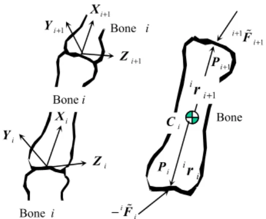
provides constraint to two adjacent bones. The motion degree-of-freedom of the joint determines the degree of the constraints. In the human body, a rolling motion occurs between the two intersecting bones. Consequently, the human joint can be modeled as a revolute or multi-revolute joint without moment constraints. Thus only three constraint forces are exerted on the joints. The internal impulses are exerted along these constrained directions at each joint when the system collides with the environment. The method to evaluate the internal impulses is briefly introduced here.
Assume that the external impulse and the velocity increments at the contact point and the joints are known. Consider the body of a serial-chain system
shown in Fig. 2. Pi is the absolute position vector of
the point of the ith body in contact with the (i-1)th
body, and iri is the position vector directing from the
mass center Ci to the contact point .Pi The
superscript in front of the variable refers to the coordinate frame in which the variable is expressed.
The contact point is assumed to be at the center of
the joint. iFi is the impulsive force at the ith contact
point. The impulsive forces between the interacting bones are equal in magnitude, but opposite in direction. By integrating the well-known Newton-Euler equations with respect to time, the relationships between the velocity increments and the internal
impulses (iFi and iτi) in the ith coordinate frame is
obtained as
Fig. 2. Bones and joints. Fig. 1. Decomposition of external force.
i X i Z i Y 1 i+ X 1 i+ Z 1 i+ Y i i − F 1 1 i i + + F 1 i+ P i P i i r 1 i i+ r i C Bone Bone i Bone i Bonei ext
F
F
extn s extF
246 Byung-Rok So, Byung-Ju Yi, and Seog-Young Han 1 1 1 [ ] , i i i i i i i C i i m∆ υ = − F + + R +F+ (14) 1 1 1 1 1 1 1 [ ] [ ] [ ] , i C i i i i i i i i i i i i i i i i i i + + + + + + + = − + − × + × τ F I ∆ ω R τ r r R F (15)
where m and [i CiI] are the mass and the moment
of inertia of the ith bone, respectively. The velocity of the mass center and angular velocity is noted as
i i
C υ
and iωi, respectively. The superscript in front of the
variable refers to the coordinate frame in which the variable is represented. [i+1iR] is the rotation matrix that transforms the (i+1)th coordinate system to ith coordinate system. When i is equal to N, it denotes the
end of the body. Thus, the impulses N+1FN+1 are a
zero vector.
If the kth body experiences external impulses, Fext
and ,τext then the above equations are modified to
1 1 1 0 [ ] [ ] , k k k k k k C k k k k ext m = − + + + + + ∆ υ F R F R F (16) 1 1 1 1 [Ck ] k k k k [ k ]k k = − k× Fk + k+ × k+ + k+ I ∆ ω r r R F 0 0 [k ] ext k I [k ] ext, + R τ + r × R F (17)
where increments of the velocity of the ith mass center and the angular velocity of the ith bone are obtained by pre-multiplying the first-order KIC to the velocity increments of the joints ∆φ
0 0 [ ] [ ] , [ ] [ ] , i i i C i T C i φ i T i i φω = = ∆ υ R G ∆φ ∆ ω R G ∆φ (18) where [ Ci] φ G and [ i] φω
G denote the first-order KIC
relating the velocity of mass center
i i
C
υ and iωi of
the ith bone to the joint velocity vector ,φ
respectively. Recalling the impulse model given in (5), the velocity increments of joints of the serial-chain module are expressed as
* 1 [ φφ] [− φv TI] ext = ∆φ I G F (19) and [ ] [ ] [ ] ι I i φ φ i φ = υ v ω G G
G denotes the first-order KIC
relating the 6×1 velocity vector at the contact point to
the joint velocity vector and [Iφφ* ] denotes the
inertia matrix.
Substituting (18) into the left-hand sides of (14) yields 0 * 1 [ ] [ ][ ] [ ] [ ] . i I i C v i T T i C i φ φφ φ ext i ext m V − = = ∆ υ R G I G F F (20)
The equations from (14) to (20) can be aggregated into a matrix form given by
[ ]D Fext =[ ]A Fint+[ ]B Fext, (21)
where
(
1 2)
1 , 2 , T T T N T int = N F F F Fand the block element
1 0 [ ] 0 [ ] , [ ] [ N] [k ] = = V D B V R and 1 3 2 3 1 3 1 3 [ ] 0 0 0 0 0 0 0 0 0 0 [ ] 0 0 [ ] . 0 0 0 0 0 0 0 0 [ ] 0 0 0 0 0 i i N N − − − − = − − I R I R A I R I
Finally, a closed-form relationship between the
internal impulse Fint and the external impulse Fext
is derived as [ ]i , int = e ext F S F (22) where
(
)
1 [Sei] [ ]= A− [ ] [ ] .D − B4. IMPULSE GEOMETRY AND MEASURE
4.1. Impulse ellipsoid for external and internal
impulse
Kim, et al. [12] proposed a normalized impulse
geometry for a serial structure. Consider Fig. 3 and let
n be the unit vector normal to the environment and
I
υ the velocity of the end-point of the serial structure.
The normalized impulse geometry in ℜ based on m
T I n υ is defined by 1. ≤ T I n υ (23)
This implies that the norm of velocity along the normal direction is confined to a unit magnitude. In
other words, the velocity of the contact point of the lower extremity is assumed to have unit magnitude in all directions.
Then, (10) can be rewritten as
* 1 ([ ][ ] [ ] ) 1. ( ). 1 I I T T Fext m e − ≤ ∈ℜ + υ υ φ φφ φ n G I G n n (24)
This represents the range of an external impulse for a given task velocity such as (23). The normalized impact geometry of the external impulse is obtained
from (24) by calculating the maximum value of Fext
for each direction of .n The resulting ellipsoid is a
form of belted ellipsoid. Similar to external impulse, the belted ellipsoid can be drawn for each joint by using (22).
4.2. Internal impulse geometry and internal impulse measure
Previous research treated only the impact geometry for external impulse that is experienced in the contacted position. In this paper, we suggest a new impulse geometry as a means to evaluate the internal impulse experienced at joints. The closed-form relation between the external impulse and the internal impulse given in (22) serves this purpose. Based on (22), a new internal impulse measure that quantifies the ability to withstand external impulse at joint is defined by
1 2
det{[ i T] [ i]}
ii = e e = n
w S S σ σ σ (25)
where ( ,σ σ1 2, σn) are the square roots of the
singular values implying values of [Sei T] [Sei]. The
characteristic of the internal impulse can be also analyzed with respect to the internal impulse measure proposed in (25). With this measure, the internal impulses of the lower extremity for a given external impulse can be evaluated.
5. SIMULATION STUDY
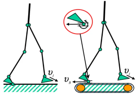
Now, we consider the human gait of Fig. 4. The human-body model is a planar 7-linked structure that mainly consists of the upper body and two legs. We
assume that the surface contact model of the supporting leg on the treadmill of Fig. 5 has one revolute joint and one prismatic joint. Here, the prismatic joint denotes the motion of the treadmill.
We compare the impulse transmission of normal walking motion on the ground with the impulse transmission on a treadmill (running machine).
Fig. 6 shows the normalized internal and external impulse geometry for normal human gait motion on the ground. The large belted ellipsoid denotes the
normalized external impulse Fext at the contact
position (i.e., heel of the front leg). The smaller ellipsoids denote the normalized internal impulse experienced at the joints. The area of the belted ellipsoid of the internal impulse becomes smaller at the proximal joint location. This is because a part of the external impulse is absorbed as a momentum change in the bones, which results in the reduction of the internal impulse at the joints. Specifically, the internal impulses of the supporting leg are smaller than those of the front leg, because of being absorbed by momentum change of the upper body. The amount of impulse in all directions can be visualized by the distance from the center of the ellipsoid to the circumference of the belted ellipsoid. The size and the
n
Iυ
T1
I= −
n υ
Normalized VelocityFig. 3. Normalized task velocity.
b elt υ B
υ
υ
I Iυ
Supporting leg Front leg(a) Walking motion (b) Walking motion
on the ground. on a treadmill.
Fig. 4. Normal walking motion on the ground and and walking motion on a treadmill.
I
υ
Iυ
Bυ
Fig. 5. Human walking model on the ground and on a treadmill.
248 Byung-Rok So, Byung-Ju Yi, and Seog-Young Han
inertia parameters of the walking model are based on the human body data given in book [16]. The subject model is male, 1.81m tall and weighs 82kg.
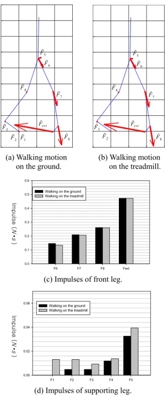
In Fig. 7, the impulses experienced while the normal walking and the walking motion on a treadmill are compared. We assume that the heel of the front leg initially contacts the ground. Based on data of human-body motion [13], in the case of normal walking, the
velocity of the front foot is given as υI =(1.2,
0.15,0) m/s.T
− However, in case of walking on the
treadmill, the heel velocity at the impact moment is
given as υI =(0, 0.15, 0) m/s− T in the earth-fixed
reference coordinate since the velocity of the treadmill
is given as υB = −( 1.2, 0, 0) m/s.T Also, the
coefficient of restitution in each case is different, because the surface on the ground and on a treadmill is composed of different materials. To find the value ‘e’ of each case, we measure the initial height of a falling object before impact and the maximum height after impact. Actually, the impact case on a treadmill is more inelastic than the case on the ground (i.e., e-ground=0.8 and e-treadmill=0.68). Therefore, we apply greater coefficient of restitution of walking on
the ground than the case of walking on a treadmill.
In Fig. 7(a) and (b), the lengths of the arrows denote the magnitude of the impulses on the foot and at each joint location. It is shown from Fig. 7(c) and (d) that both cases receive similar quantitative impulses on the foot (external impulse). However, the walking motion on a treadmill receives more internal impulses at the joints of supporting leg.
There are three parameters that affect the magnitude of the external impulse; the velocity
difference
(
υ
I−
υ
B),
the norm of dynamics ([GφυI]1 1 1
[ ] [ I]T [ B][ ] [ B] ) ,T
φφ − φυ + φυ φφB − φυ −
I∗ G G I∗ G and the
coefficient of restitution (e). Only looking at the
magnitude of ‘e’, the external impulse on the ground should be greater than that on the treadmill. However, the norm of the dynamics becomes smaller in the case of walking on the ground. This is an important point. The kinematic model on the treadmill is different because there is an additional prismatic joint between (a) Internal impulse. (b) External impulse.
Fig. 6. Normalized internal and external impulse geometry of human walking motion on the ground. ext F 1 F 2 F 3 F 4 F 5 F 6 F 7 F 8 F ext F 2 F 3 F 4 F 5 F 6 F 7 F 8 F
(a) Walking motion (b) Walking motion on the ground.
on the treadmill.
F6 F7 F8 Fext 0.0 0.1 0.2 0.3 0.4 0.5 0.6
Walking on the ground Walking on the treadmill
(c) Impulses of front leg.
F1 F2 F3 F4 F5
0.00 0.02 0.04 0.06
Walking on the ground Walking on the treadmill
(d) Impulses of supporting leg.
Fig. 7. Internal and external impulses of human walking. I m p u l s e ( N • s ) I m p u l s e ( N • s )
the rear foot and the treadmill. Accordingly, this additional joint takes on additional dynamics. Thus,
the norm of [Iφφ∗ ] becomes greater. Resultantly, the
norm of ([ I][ ] [1 I]T [ B][ ] 1 φυ φφ − φυ + φυ φφB − G I∗ G G I∗ 1 [ B] )T φυ −
G becomes smaller as compared to that on
the treadmill.
This analysis tells us that exercise using a treadmill may damage the knee and ankle joints of the supporting leg more than the case of normal walking on the ground. Thus, long-term exercise on a treadmill at high speed is not recommended. This result is coincident with the previous kinesiology research [14].
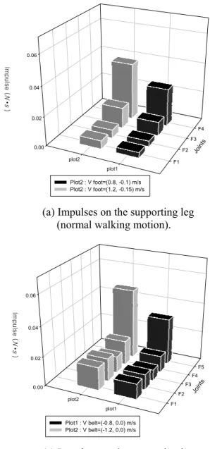
Fig. 8 shows the simulation results of normal walking and walking motion on the treadmill for several different speeds. Specifically, Fig. 8(a) and (c)
denote the impulses exerted on the supporting leg and Fig. 8(b) and (d) denote the impulses exerted on the front leg. According to the simulation results, the faster the belt of the treadmill, the larger the external impulse (Fext) experienced at the heel point of the human front foot and internal impulses (F1~F8) experienced at the joints. The highest block in Fig. 8(b) denotes the external impulse at the end of the hill of the front leg. The amounts of external impulse are
about 0.59N s⋅ and 0.35N s⋅ for each speed case,
respectively.
6. IMPLEMENTATION
We developed a force platform to measure the vertical and horizontal ground-reaction impulses. Fig. 9(a) shows the force platform that is composed of two
I m p u l s e ( N • s ) 0.00 0.02 0.04 0.06 F1 F2 F3 F4 plot1 plot2 Join ts Plot2 : V foot=(0.8, -0.1) m/s Plot2 : V foot=(1.2, -0.15) m/s I m p u l s e ( N • s ) 0.0 0.1 0.2 0.3 0.4 0.5 0.6 F5 F6 F7 Fext plot1 plot2 Join ts Plot1 : V foot=(0.8, -0.1) m/s Plot2 : V foot=(1.2, -0.15) m/s
(a) Impulses on the supporting leg (b) Impulses on the front leg
(normal walking motion).
(normal walking motion).
I m p u l s e ( N • s ) 0.00 0.02 0.04 0.06 F1 F2 F3 F4 F5 plot1 plot2 Join ts Plot1 : V belt=(-0.8, 0.0) m/s Plot2 : V belt=(-1.2, 0.0) m/s I m p u l s e ( N • s ) 0.0 0.1 0.2 0.3 0.4 0.5 0.6 F6 F7 F8 Fext plot1 plot2 Join ts Plot1 : V belt=(-0.8, 0.0) m/s Plot2 : V belt=(-1.2, 0.0) m/s
(c) Impulses on the supporting leg (d) Impulses on the front leg
(walking motion on the treadmill). (walking motion on the treadmill). Fig. 8. External impulses and internal impulses.
250 Byung-Rok So, Byung-Ju Yi, and Seog-Young Han
steel plates (1500 860 4mm)× × and a cantilever
module between the two steel plates. The cantilever module consists of the four aluminum beams connected to a cross-shaped cantilever.
A strain gauge is bonded to the surface of each cantilever as shown in Fig. 9(b) and connected to the external signal-conditioning module (Tokyo Sokki DRA-101). The four strain gages for measuring the vertical impulse are located at the distal ends of each cantilever, and the two strain gages for measuring the horizontal impulse are bonded to the horizontal beam
of the cross-shaped cantilever. The vertical impulse is calculated by the average impulse of the four stain gages bonded to the cross-shaped cantilever, and the horizontal impulse is calculated as the average value of the two impulses measured in the horizontal cantilever. The experimental proto-type appears in Fig. 9(c). For the walking experiment on a treadmill, the treadmill is installed on a force platform. And for the normal walking experiment, we remove the treadmill.
7. EXPERIMENTATION
Fig. 10 shows the resultant impulse measured by the force platform in case of the normal walking and walking on the treadmill for several walking velocities, respectively. The sampling time is 1ms. In the plot, the part of sudden impulse, which is represented by arrows, is the moment that the heel contacts the ground. Due to the weight of the human walking on the treadmill, the value of the external impulse is
being elevated by about 1N s.⋅ Thus, subtracting
1N s⋅ from the experimental data gives a real
external impulse value. Simulation results in the previous section showed that the faster the velocity of walking, the larger the impulse on the foot of front leg (external impulse) was received. The same trend can be observed in the experiment results. The maximum magnitudes of the external impulses are about
0.541N s⋅ and 0.381N s,⋅ respectively. This
magnitude of the external impulse is almost identical to the simulation result of Fig. 8. Therefore, the experimental result shows that our proposed impulse model is an effective tool to analyze the impact phenomenon occurring on the treadmill.
Note that there is no direct way of measuring the internal impulses experienced at joints experimentally. However, since the internal impulse has a functional relation with the external impulse as described in (22), the internal impulse can be estimated by (22) as long as the external impulse is measurable at experimenta-tion.
8. CONCLUSIONS
Previous works related to analysis of human walking motion are mostly based on experimental methodology. This paper proposes an analytical methodology. For this, an impulse modeling and impulse measure for a human lower extremity model are introduced for analysis of impulses experienced in the human walking motion. Based on these analytic tools developed in this study, it is shown that long-term exercise on treadmill tends to give more impulse to the joints of the supporting leg. Also, we demonstrate the effectiveness of the proposed analytical approach by performing experimentation. For this, a force platform was developed and used to
① Top plate ④ Bottom plate ② Support beam ⑤ Support block ③ Base plate ⑥ Cross beam
(a) Diagram of the force platform.
(b) Distal end of cross-shape beam.
(c) Force platform. Fig. 9. The force platform.
strain gage (vertical) strain gage (horizontal) See Fig. 8(b) for details vertical horizontal
measure the external impulses during human walking. The analytical tools and practices developed in this work can be applied effectively to impulse analyses of several sports actions, as well as robotic applications that emphasize impact control. Specially, athletes exert a greater impact on a playing object when compared to daily, routine human-body motions. Ongoing work is to develop a methodology that maximizes the external impulse applied to the playing objects and minimizes the internal impulses experienced at human joints.
REFERENCES
[1] D. K. Richard, B. S. James, D. A. Douglas, D. P. Robert, and W. S. Robert, “Mathematical model of the lower extremity joint reaction forces using Kane’s method of dynamics,” The Journal of
Biomechanics, vol. 31, pp. 185-189, 1998.
[2] P. B. Alain, B. Antoine, G. Andre, and L. Jean-rene, “A treadmill ergometer for three-dimensional ground reaction forces measure-ment during walking,” The Journal of
Biomechanics, vol. 34, pp. 105-112, 2001.
[3] R. Conley, K. Tulchin, G. Harris, P. Smith, J. Humm, and S. Hassani, “Pediatric sports medicine: An evolution of applications of motion analysis,” Pediatric Gaits: A New
Millennium in Clinical Care and Motion Analysis Technology, pp. 116-223, 2000.
[4] R. M. Brach, “Classical planar impact theory
and the tip impact of a slender rod,” IEEE
Journal of Impact Engineering, vol. 13, no. 1, pp.
21-33, 1993.
[5] G. Ferretti, G. Magnani, and A. Zavala Rio, “Impact modeling and control for industrial manipulators,” IEEE Control System Magazine, vol. 18, no. 4, pp. 65-71, 1998.
[6] I. D. Walker, “Impact configurations and measures for kinematically redundant and multiple armed robot systems,” IEEE Trans. on
Robotics Automation, vol. 12, no. 5, pp. 670-683,
1994.
[7] H.-T. Liao, and M. C. Leu, “Analysis of impact
in robotic peg-in-hole assembly,” Robotica, vol.
16, no. 3, pp. 347-356, 1998.
[8] Y.-F. Zheng, and H. Henami, “Mathematical modeling of a robot collision with its environment,” IEEE Journal of Robotic System, vol. 2, no. 3, pp. 289-307, 1985.
[9] J. Wittenburg, Dynamics of Systems of Rigid
Bodies, Teubner, Stuttgart, 1977.
[10] S. H. Lee, B.-J. Yi, S. H. Kim, and Y. K. Kwak, “Modeling and analysis of internal impact for general classes of robotic mechanism,” Proc.
IEEE/RSJ Int. Conf. Robotics. Systems, pp.
1955-1962, 2000.
[11] R. A. Freeman and D. Tesar, “Dynamic modeling of serial and parallel mechanisms/ robotic systems, Part I-Methodology, Part II-Applications,” Proc. ASME Int. Conf. Biennial
Mechanisms, vol. 15-3, pp. 7-27, 1998.
[12] J. H. Kim, W. K. Chung, and Y. G. Youm, “Normalized impact geometry and performance index for redundant manipulators,” Proc. IEEE
Int. Conf. Robotics. Automation, San Francisco,
pp. 1714-1719, 2000.
[13] M. W. Whittle, Gait Analysis: An Introduction, 2nd edition, Butterworth-Heinemann, Oxford, 1996. I m p u l s e ( N • s ) I m p u l s e ( N • s ) time (sec) 0.0 0.2 0.4 0.6 0.8 1.0 1.2 0.0 0.2 0.4 0.6 0.8 1.0 1.2 1.4 1.6 1.8 walking velocity : 0.8 m/s walking velocity : 1.2 m/s
(a) External impulses (normal walking).
time (sec) 0.0 0.2 0.4 0.6 0.8 1.0 1.2 0.0 0.2 0.4 0.6 0.8 1.0 1.2 1.4 1.6 1.8 treadmill velocity : 0.8 m/s treadmill velocity : 1.2 m/s
(b) External impulses (treadmill walking). Fig. 10. Impulses measured by the force platform. Table. 1. The size and inertia parameters of the
human model of Fig. 4. (height: 1.8m, weight: 80kg)
Length (m) Mass (kg) Inertia(kg m )i 2
Upper body 0.521 56.252 0.1000
Thigh 0.443 8.201 0.0610 Calf 0.445 3.527 0.0510 Foot 0.2 1.146 0.0011
252 Byung-Rok So, Byung-Ju Yi, and Seog-Young Han
[14] http://www.umich.edu/~mvs330/w00/kneedfulth ings/main.html, Motion Analysis Projects Homepage, Division of Kinesiology, University of Michigan.
[15] B. R. So, B.-J. Yi, and W. K. Kim, “Impulse analysis and its applications to dynamic environment,” Proc. ASME Int. Conf. Biennial
Mechanisms, pp. 109-114, 2002.
[16] D. B. Chaffin, G. B. J. Andersson, and B. J.
Martin, Occupational Biomechanics, 3rd editon,
Wiley-Interscience, 1999.
[17] Y. H. Chang, J. E. A. Bertram, and A. Ruina, “A dynamic force and moment analysis system for brachiation,” The Journal of Experimental
Biology, vol. 200, pp. 3013-3020, 1997.
[18] A. Tozeren, Human Body Dynamics: Classical
Mechanics and Human Movement, Springer
Press, 1999.
[19] S. C. Kang, K. Komoriya, K. Yokoi, T. Koutoku, and K. Tanie, “Utilization of inertial effect in damping-based posture control of mobile manipulator,” Proc. IEEE Int. Conf. Robotics.
Automation, Seoul, Korea, pp. 1277-1282, 2001.
[20] K. G. M. Gerritsen, A. J. Bogert, and B. M. Nigg, “Direct dynamics simulation of the impact phase in heel-toe running,” The Journal of
Biomechanics, vol. 28, pp. 661-668, 1995.
[21] M. Nahon and J. Angles, “Reducing the effects
of shocks using redundant actuation,” Proc.
IEEE Int. Conf. Robotics and Automation, pp.
238-243, 1991.
Byung-Rok So received the B.S. and
M.S. degrees in Control and Instru-mentation Engineering from Hanyang University, Korea in 1997 and 2000, respectively, and the Ph.D. degree in Electronics, Electrical, Control and Instrumentation Engineering from Hanyang University, in 2006. Currently, he is a Senior Researcher in the Division for Applied Robot Technology, the Korea Institute of Industrial Technology(KITECH). His research interests include design and control of Humanoid and Android robots, the modeling of redundant and parallel mechnisms, and impact control.
Byung-Ju Yi received the B.S. degree
from the Department of Mechanical Engineering, Hanyang University, Seoul, Korea in 1984, and the M.S. and Ph.D. degrees from the Depart-ment of Mechanical Engineering, University of Texas at Austin, in 1986 and 1991, respectively. From January 1991 to August 1992, he was a Post-Doctoral Fellow with the Robotics Group, University of Texas at Austin. From September 1992 to February 1995, he was an Assistant Professor in the Department of Mechanical and Control Engineering, Korea Institute of Technology and Education (KITE), Chonan, Chungnam, Korea. In March 1995, he joined Hanyang University, Ansan, Gyeonggi-do, Korea as an Assistant Professor in the Department of Control and Instrumentation Engineering. Currently, he is a Professor with the School of Electrical Engineering and Computer Science, Hanyang University. He stayed at Johns Hopkins University as a visiting professor from January 2004 to January 2005. His research interests include design, control, and application of surgical robots, parallel manipulator, micromanipulator, haptic device, and anthropomorphic manipulator systems.
Seog-Young Han received the B.S.
degree from the Department of Mechanical Engineering, Hanyang University, Seoul, Korea in 1982, and the M.S. and Ph.D. degrees from the Department of Mechanical Engineer-ing, Oregon State University at Oregon, in 1984 and 1989, respectively. Since 1995 he has been in the Department of Mechanical Engineering, Hanyang University at Seoul, Korea. Currently, he is a Professor in the same department. His research interests include solid mechanics, fracture mechanics, optimum design.