ICCAS2005 June 2-5, KINTEX, Gyeonggi-Do, Korea
The inspection and maintenance of pressurizer internal structures by using the
tele-operated robotic manipulator in nuclear power plants
Poong Woo Jeon*, Seung Ho Jung
*, Yongchil Seo
*, Chang Hwan Choi
*,
and Seungho Kim
** Nuclear Robotics Lab., Korea Atomic Energy Research Institute, 150 Deokjin-dong, Yusong, Daejon, 305-353, Korea
.
(Tel : +82-42-868-8839; E-mail: [email protected])Abstract : A pressurizer is one of the major safety related equipment of nuclear power plants. In order to inspect and maintain the internal structures of a pressurizer, jumpers have to enter the pressurizer, in spite of the high dose exposure. Therefore, a tele-operated robotic manipulator has been developed, which consists of four parts with 2DOFs arms, a gripper, base frame, and control console. The task of this robotic manipulator is to extract the damaged electric heaters and inspect the internal structure of the pressurizer. The gripper hanging from the manipulator approaches the heaters and extracts the damaged heater by using a self-locking mechanism. In order to investigate the structural stability of the robotic manipulator, a stress analysis has been performed by using the ANSYS code.
The results of this paper include the position control and vibration control of robotic gripper and the development of processing visual information for a vision sensor.
there are a lot of difficulties in controlling the robotic manipulator.
1. INTRODUCTION
The reactor coolant system in a nuclear power plant consists of a reactor, steam generators, reactor coolant pumps, and a pressurizer. They play a key role in supplying high pressure steam to the turbines. Among them, the pressurizer controls the pressure variation of the reactor coolant system, which consists of a pressure vessel, electric heaters and a spray nozzle. Sometimes, though not frequently, the electric rod heaters at the bottom of the pressurizer are damaged by an overheating. Therefore, it is necessary to inspect and maintain them periodically. But the inside of a pressurizer is contaminated by radioactivity, during inspecting and repairing, so a radiation exposure to workers is inevitable. In such a case, the use of a robot for inspecting and maintaining the pressurizer reduces the radiation exposure to the workers, so it can improve the performance of a repair and the economic efficiency.
In this research, a tele-operated robot manipulator was developed for the inspection and maintenance of the pressurizer, which consists of four parts with 2 DOFs arms, a gripper, base frame, and a control console. In order to investigate the structural stability of the robotic manipulator, a stress analysis has been performed by using the ANSYS code. The robotic system should satisfy the important design constraints for the successful achievement of the assigned tasks in a limited working area.
The results of this research include the dynamic modeling analysis, a vision processing algorithm for measuring the center position of the gripper, the position control of the robot and the vibration control of the robot gripper. Particularly, the vision processing results would be useful for future research to control the vibration of the gripper more efficiently.
2. DEVELUPMENT OF THE ROBOT SYSTEM
2.1. Design considerations
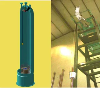
Fig. 1 shows the pressurizer and the developed robot. As shown in Fig. 1, the internal of the pressurizer is narrow, so
Keywords : pressurizer, robotic manipulator, image processing, vibration control.
Fig. 1. Pressurizer and robot system in a real size mock-up. Hence, for the achievement of the assigned tasks in a limited working area, the robot has to satisfy the following conditions :
- Pressurizer has a cylindrical shape, inner diameter is 2.8m, height is 13m, and a water spray nozzle is equipped at the upper plate. Therefore, it has to be designed to avoid collisions in the limited working area.
-The inside of the pressurizer is contaminated by radioactivity, so the robot needs to be hardened to a radiation
- The diameter of the manhole is 40cm, it should be possible to mount and insert the robot without any constraints.
- It has to extract the damaged heaters, which are located at a 9m distance downward from the manhole.
- For the facility of mount and remove, the robot has to be light, flexible, and easy to control.
ICCAS2005 June 2-5, KINTEX, Gyeonggi-Do, Korea
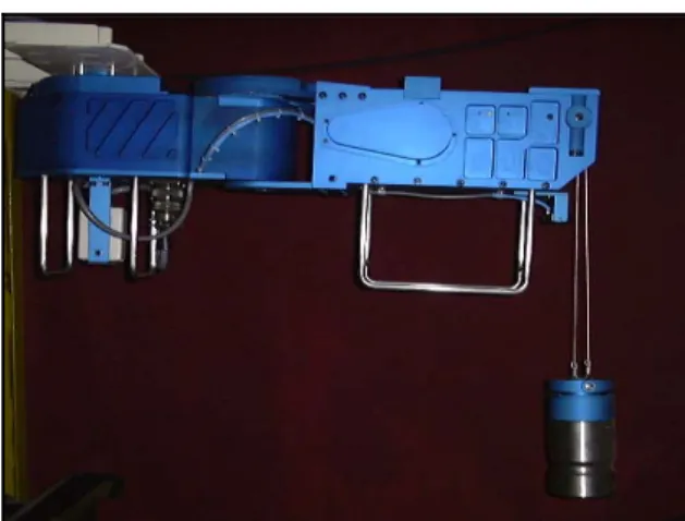
To satisfy the above conditions, a tele-operated robotic
manipulator has been developed. Fig. 2 shows the general layout of the system and Fig. 3 shows the robotic manipulator attached to the flange.
Where
δ
k ; Spring force,
A ; Reflection force at the horizontal plane,
R
B
R
; Reflection force at the inclined plane,P
; Reflection force at the electric heater, HW
; Weight of the electric heater,μ
; Friction coefficient.Because the gripper is composed of three balls, if the condition of Eq. (2) is satisfied, the gripper can extract electric heaters. H
W
P
≥
μ
3
. (2)Fig. 2. General layout of the system.
Fig. 3. Robotic manipulator on the flange.
Table 1 shows the designed parameters of the robot. It was designed with an adequate weight so that it can be carried by the workers at the field test.
Table 1. Parameters of the robot arms.
Fig. 4. Internal structure of the gripper
3. IMAGE PROCESSING FOR THE DETECTION
OF THE POSITION OF GRIPPER.
To detect the position of the gripper, a camera was used and an image processing algorithm was applied [1-2].
Image processing algorithm is as follows : 1. Acquisition of the vision data ;
Acquired vision data has a RGB 24 bit format per 1 pixel and the resolution is 320×240.
Items First arm
Middle
arm Base frame Gripper Weight
(kg) 10 15
Programming software is based on Visual ++
6
.
0
C
andDirectX 8.1. 20 6
2. Setting the vision information of the gripper ;
Set the vision information of the gripper such as, the RGB min/max value boundary, initial position, size of the gripper, etc.
Lenth×width
×height(cm) 40×16×17 53×18×17 100×60×80
φ
10×133. Changing RGB data format to binary format ;
To reduce the image processing time, if the RGB value of a data pixel exists on the RGB value boundary of the gripper, set the pixel to ‘1’, else ‘0’ for all the vision data.
4. Labeling ; 2.2 Design of the gripper with balls
If there are several areas, which have the same vision information as the gripper, label them with different numbers respectively.
Fig. 4 shows the applied forces to the gripper when it extracts the electric heater.
The equilibrium equation is expressed as :
5. Size filtering ;
After labeling, from comparing every area size with the gripper size set at step 2, choose the gripper area.
} cos ) 1 ( ) 1 )(sin 1 ){( 1 ( ) 1 cos sin (
α
μ
α
μ
μ
α
α
μ
δ
− + + + + + − = k P, (1) 6. Determine the gripper position ;
Determine a central point of the gripper area as the correct
ICCAS2005 June 2-5, KINTEX, Gyeonggi-Do, Korea
gripper position. 1 0 sin1 cos1 ,
y x l x x= +
θ
θ
(3) , sin1 0 1 y l y y= +θ
(4)Fig. 5 shows the GUI program for finding the gripper position at every control time. Also it can be used as a
monitoring program when the robot is controlled manually. cos cos .
1 1 1 y x l z=−
θ
θ
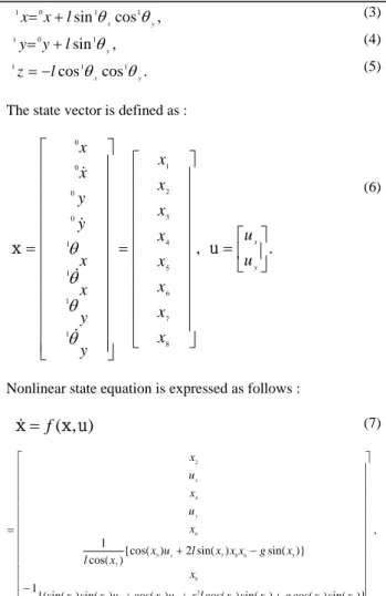
(5)The state vector is defined as :
.
,
8 7 6 5 4 3 2 1 1 1 1 1 0 0 0 0⎥
⎦
⎤
⎢
⎣
⎡
=
⎥
⎥
⎥
⎥
⎥
⎥
⎥
⎥
⎥
⎥
⎦
⎤
⎢
⎢
⎢
⎢
⎢
⎢
⎢
⎢
⎢
⎢
⎣
⎡
=
⎥
⎥
⎥
⎥
⎥
⎥
⎥
⎥
⎥
⎥
⎥
⎥
⎦
⎤
⎢
⎢
⎢
⎢
⎢
⎢
⎢
⎢
⎢
⎢
⎢
⎢
⎣
⎡
=
y xu
u
x
x
x
x
x
x
x
x
y
y
x
x
y
y
x
x
u
x
θ
θ
θ
θ
&
&
&
&
(6)Nonlinear state equation is expressed as follows :
)
,
(
x
u
x
&
=
f
(7 Fig. 5. GUI for finding the gripper position at every controltime. ) , )} sin( ) cos( ) sin( ) cos( ) cos( ) sin( ) {(sin( 1 )} sin( ) sin( 2 ) {cos( ) cos( 1 7 5 7 7 2 6 7 7 5 8 5 6 8 7 5 7 6 4 2 ⎥ ⎥ ⎥ ⎥ ⎥ ⎥ ⎥ ⎥ ⎥ ⎥ ⎥ ⎥ ⎦ ⎤ ⎢ ⎢ ⎢ ⎢ ⎢ ⎢ ⎢ ⎢ ⎢ ⎢ ⎢ ⎢ ⎣ ⎡ + + + − − + = x x g x x l x u x u x x l x x g x x x l u x x l x u x u x y x x y x
4. MODELING AND CONTROL OF THE 2DOFS
GANTRY TYPE CRANE
A coordinate system of the gantry type 2DOFs crane is considered as Fig. 6[3-4].
0 X 0 Y 0
Z
1 X 1 Y 1Z
xθ
1 yθ
1 m M ) 0 , , (0 0 y x ) , , (1 1 1 z y x lWhere
g
is the gravity acceleration.To apply the linear control algorithm, linearize
f
(
x
,
u
)
using Jacobian at equilibrium state (1
=
1=
1=
1=
0
y x yx
θ
θ
θ
θ
&
&
)and then
Δ
x
is expressed as :u
x
* *B
A
x
=
+
Δ
(8) , 1 0 0 0 0 1 0 0 1 0 0 0 0 1 0 0 0 0 0 0 0 0 0 1 0 0 0 0 0 0 0 0 0 0 0 0 0 0 0 0 1 0 0 0 0 0 0 0 0 0 0 0 0 0 0 0 0 0 1 0 0 0 0 0 0 0 0 0 0 0 0 0 0 0 0 0 1 0 u x ⎥ ⎥ ⎥ ⎥ ⎥ ⎥ ⎥ ⎥ ⎥ ⎥ ⎥ ⎥ ⎦ ⎤ ⎢ ⎢ ⎢ ⎢ ⎢ ⎢ ⎢ ⎢ ⎢ ⎢ ⎢ ⎢ ⎣ ⎡ − + ⎥ ⎥ ⎥ ⎥ ⎥ ⎥ ⎥ ⎥ ⎥ ⎥ ⎥ ⎥ ⎦ ⎤ ⎢ ⎢ ⎢ ⎢ ⎢ ⎢ ⎢ ⎢ ⎢ ⎢ ⎢ ⎢ ⎣ ⎡ − − = l l l g l gFig. 6. Coordinate systems of a 2DOFs overhead crane.
0 0 0,Y,Z
X is a reference coordinate and 1 is a trolley
coordinate. is an origin of the trolley coordinate related to the reference coordinate.
1 1
,
Y
,
Z
X
)
0
,
,
(
0 0y
x
xθ
1 and yθ
1 are angles ofthe load swing related to the axis and axis respectively. is the trolley mass and is the load mass. The trolley is moving on the -plane and is the steel wire length. So the load position in the reference coordinate,
, is given as : 1 X 1
Y
M m XY l)
,
,
(
1 1 1z
y
x
Where * * are the Jacobian matrix.
, B
A *
A and B can be decoupled as state variables related to the x *
axis and y axis respectively, (8) can be considered as 2 independent linear state equations as follows :
ICCAS2005 June 2-5, KINTEX, Gyeonggi-Do, Korea
, 1 0 1 0 0 0 0 1 0 0 0 0 0 0 0 0 0 1 0 x x x x x x x u l X l g u B X A X ⎥ ⎥ ⎥ ⎥ ⎥ ⎦ ⎤ ⎢ ⎢ ⎢ ⎢ ⎢ ⎣ ⎡ + ⎥ ⎥ ⎥ ⎥ ⎥ ⎦ ⎤ ⎢ ⎢ ⎢ ⎢ ⎢ ⎣ ⎡ − = + = & (9) . 1 0 1 0 0 0 0 1 0 0 0 0 0 0 0 0 0 1 0 y y y y y y y u l X l g u B X A X ⎥ ⎥ ⎥ ⎥ ⎥ ⎦ ⎤ ⎢ ⎢ ⎢ ⎢ ⎢ ⎣ ⎡ + ⎥ ⎥ ⎥ ⎥ ⎥ ⎦ ⎤ ⎢ ⎢ ⎢ ⎢ ⎢ ⎣ ⎡ − = + = & (10) where
.
,
8 7 4 3 6 5 2 1⎥
⎥
⎥
⎥
⎦
⎤
⎢
⎢
⎢
⎢
⎣
⎡
=
⎥
⎥
⎥
⎥
⎦
⎤
⎢
⎢
⎢
⎢
⎣
⎡
=
x
x
x
x
X
x
x
x
x
X
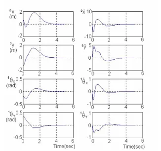
x yFig. 8. Position and velocity of the trolley and the vibration angle and angular velocity of the load.
Because the system modeling could be linearized as above, a full-state-feedback controller can be designed, which can determine the eigenvalues of arbitrarily.
y x
A
A ,
5. CONCLUSIONS
That is,
In this paper, we developed a tele-operated robotic manipulator, which can extract damaged heaters and inspect the internal structures of a pressurizer, which is one of the safety related equipment in nuclear power plants.
.
,
y y y x x xX
K
u
X
K
u
−
=
−
=
(11)It was designed to guarantee a sufficient enough moving space in a limited working area, and through the stress analysis, which has been performed by using the ANSYS code, the structural stability of the robotic manipulator was investigated. When we determine as with Eq. (12) by using the
Ackermann’s Fomular, Fig. 7 shows the trace of the positions of the trolley and the load. Also Fig. 8 shows the position and velocity of the trolley arm and the vibration angle and angular velocity of the load. Vibration of the load is converged to zero by suitably adjusting the system eigenvalue[5].
y x
K
K ,
An image processing algorithm was applied to detect the position of the gripper, and the simulation studies for the dynamic modeling of the 2DOFs crane show good results for the position and vibration control.
. 910.963] 281.147 113.784 [89.37 = K 910.963], -281.147 -113.784 [89.36 = K y x (12)
ACKNOWLEDGMENT
This work was performed under the long-term nuclear R&D program sponsored by the Korea Ministry of Science and Technology.
REFERENCES
[1] J. H. Kim, Robot soccer system, Daeyeongsa, Korea, 2000.
[2] G. S. Gupta, C. H. Messom, and S. Demidenko, “Real-time identification and predictive control of fast mobile robots using global vision sensing”, IEEE Trans. on
Instrumentation and Measurement, Vol. 54, pp. 200-214,
2005.
[3] S. K. Cho and H. H. Lee, “An anti-swing control of a 3-dimensional overhead crane”, Proc. of AACC, pp. 1037-1041, 2000.
[4] J. G. Lee, “The Modeling and position control of overhead cranes”, Trans. of KSME, Vol. 25, No. 12, pp. 1919-1925, 2001.
Fig. 7. Trace of the positions of the trolley and the load. (Line : trolley; circle : load)
[5] H. Lee, "Modeling and control of a 2-dimensional overhead crane", Proc. of ASME DSMC, Vol. 61, pp. 535-542, 1997.